1
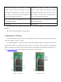
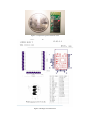
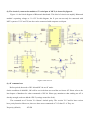
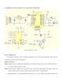
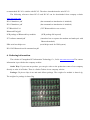
HC Serial Bluetooth Products
User Instructional Manual
1 Introduction
HC serial Bluetooth products consist of Bluetooth serial interface module and Bluetooth adapter, such
as:
(1) Bluetooth serial interface module:
Industrial level:
HC-03, HC-04(HC-04-M, HC-04-S)
Civil level:
HC-05, HC-06(HC-06-M, HC-06-S)
HC-05-D, HC-06-D (with baseboard, for test and evaluation)
(2) Bluetooth adapter:
HC-M4
HC-M6
This document mainly introduces Bluetooth serial module. Bluetooth serial module is used for
converting serial port to Bluetooth. These modules have two modes: master and slaver device. The
device named after even number is defined to be master or slaver when out of factory and can’t be
changed to the other mode. But for the device named after odd number, users can set the work mode
(master or slaver) of the device by AT commands.
HC-04 specifically includes:
Master device:
HC-04-M, M=master
Slave device:
HC-04-S, S=slaver
The default situation of HC-04 is slave mode. If you need master mode, please state it clearly or
place an order for HC-O4-M directly.The naming rule of HC-06 is same.
When HC-03 and HC-05 are out of factory, one part of parameters are set for activating the device.
The work mode is not set, since user can set the mode of HC-03, HC-05 as they want.
The main function of Bluetooth serial module is replacing the serial port line, such as:
1. There are two MCUs want to communicate with each other. One connects to Bluetooth master
device while the other one connects to slave device. Their connection can be built once the pair is made.
This Bluetooth connection is equivalently liked to a serial port line connection including RXD, TXD
signals. And they can use the Bluetooth serial module to communicate with each other.
2. When MCU has Bluetooth salve module, it can communicate with Bluetooth adapter of
computers and smart phones. Then there is a virtual communicable serial port line between MCU and
computer or smart phone.
3. The Bluetooth devices in the market mostly are salve devices, such as Bluetooth printer,
Bluetooth GPS. So, we can use master module to make pair and communicate with them.
Bluetooth Serial module’s operation doesn’t need drive, and can communicate with the other
Bluetooth device who has the serial. But communication between two Bluetooth modules requires at
least two conditions:
(1) The communication must be between master and slave.
(2) The password must be correct.
However, the two conditions are not sufficient conditions. There are also some other conditions
basing on different device model. Detailed information is provided in the following chapters.
In the following chapters, we will repeatedly refer to Linvor’s (Formerly known as Guangzhou HC
Information Technology Co., Ltd.) material and photos.
2 Selection of the Module
The Bluetooth serial module named even number is compatible with each other; The salve module
is also compatible with each other. In other word, the function of HC-04 and HC-06, HC-03 and HC-05
are mutually compatible with each other. HC-04 and HC-06 are former version that user can’t reset the
work mode (master or slave). And only a few AT commands and functions can be used, like reset the
name of Bluetooth (only the slaver), reset the password, reset the baud rate and check the version
number. The command set of HC-03 and HC-05 are more flexible than HC-04 and HC-06’s. Generally,
the Bluetooth of HC-03/HC-05 is recommended for the user.
Here are the main factory parameters of HC-05 and HC-06. Pay attention to the differences:
HC-05
HC-06
Master and slave mode can be switched
Master and slave mode can’t be switched
Bluetooth name: HC-05
Bluetooth name: linvor
Password:1234
Password:1234
Master role: have no function to remember the last
paired salve device. It can be made paired to any
slave
device.
In
other
words,
just
set Master role: have paired memory to remember
AT+CMODE=1 when out of factory. If you want last slave device and only make pair with that
HC-05 to remember the last paired slave device device unless KEY (PIN26) is triggered by high
address like HC-06, you can set AT+CMODE=0 level. The default connected PIN26 is low level.
after paired with the other device. Please refer the
command set of HC-05 for the details.
Pairing: The master device can not only make pair
with
the
specified
Bluetooth
address,
like
cell-phone, computer adapter, slave device, but Pairing: Master device search and make pair with
also can search and make pair with the slave the slave device automatically.
device automatically.
Typical method:
On some specific conditions,
Typical method: On some specific conditions, master and slave device can make pair with each
master device and slave device can make pair with other automatically.
each other automatically. (This is the default
method.)
Multi-device communication: There is only point Multi-device communication: There is only point
to point communication for modules, but the to point communication for modules, but the
adapter can communicate with multi-modules.
adapter can communicate with multi-modules.
AT Mode 1: After power on, it can enter the AT
mode by triggering PIN34 with high level. Then
the baud rate for setting AT command is equal to
the baud rate in communication, for example:
AT Mode: Before paired, it is at the AT mode.
9600.
After paired it’s at transparent communication.
AT mode 2: First set the PIN34 as high level, or
while on powering the module set the PIN34 to be
high level, the Baud rate used here is 38400 bps.
Notice: All AT commands can be operated only
when the PIN34 is at high level. Only part of the
AT commands can be used if PIN34 doesn’t keep
the high level after entering to the AT mode.
Through this kind of designing, set permissions for
the module is left to the user’s external control
circuit, that makes the application of HC-05 is very
flexible.
During the process of communication, the module
can enter to AT mode by setting PIN34 to be high
level. By releasing PIN34, the module can go back During the communication mode, the module
to communication mode in which user can inquire can’t enter to the AT mode.
some information dynamically. For example, to
inquire the pairing is finished or not.
Default
communication
baud
rate:
9600, Default
communication
baud
rate:
4800-1.3M are settable.
1200-1.3M are settable.
KEY: PIN34, for entering to the AT mode.
KEY: PIN26, for master abandons memory.
9600,
LED1: PIN31, indicator of Bluetooth mode. Slow
flicker (1Hz) represents entering to the AT mode2,
while fast flicker(2Hz) represents entering to the LED: The flicker frequency of slave device is
AT mode1 or during the communication pairing. 102ms. If master device already has the memory
Double flicker per second represents pairing is of slave device, the flicker frequency during the
finished, the module is communicable.
pairing is 110ms/s. If not, or master has emptied
LED2: PIN32, before pairing is at low level, after the memory, then the flicker frequency is 750m/s.
the pairing is at high level.
After pairing, no matter it’s a master or slave
The using method of master and slaver’s indicator device, the LED PIN is at high level.
is the same.
Notice: The LED PIN connects to LED+ PIN.
Notice: The PIN of LED1 and LED2 are connected
with LED+.
Consumption: During the pairing, the current is Consumption: During the pairing, the current is
fluctuant in the range of 30-40mA. The mean fluctuant in the range of 30-40 m. The mean
current is about 25mA. After paring, no matter current is about 25mA. After paring, no matter
processing communication or not, the current is processing communication or not, the current is
8mA. There is no sleep mode. This parameter is 8mA. There is no sleep mode. This parameter is
same for all the Bluetooth modules.
same for all the Bluetooth modules.
Reset: PIN11, active if it’s input low level. It can Reset: PIN11, active if it’s input low level. It can
be suspended in using.
be suspended in using.
Level: Civil
Level: Civil
The table above that includes main parameters of two serial modules is a reference for user
selection.
HC-03/HC-05 serial product is recommended.
3. Information of Package
The PIN definitions of HC-03, HC-04, HC-05 and HC-06 are kind of different, but the package size
is the same: 28mm * 15mm * 2.35mm.
The following figure 1 is a picture of HC-06 and its main PINs. Figure 2 is a picture of HC-05 and
its main PINs. Figure 3 is a comparative picture with one coin. Figure 4 is their package size information.
When user designs the circuit, you can visit the website of Guangzhou HC Information Technology Co.,
Ltd. (www.wavesen.com) to download the package library of protle version.
Figure 1
HC-06
Figure 2
HC-05
Figure 3 Comparative picture with one coin
Figure 4 Package size information
4. The Using and Testing Method of HC-06 for the First Time
This chapter will introduce the using method of HC-06 in detail. User can test the module
according to this chapter when he or she uses the module at the first time.
PINs description:
PIN1
UART_TXD , TTL/CMOS level, UART Data output
PIN2
UART_RXD, TTL/COMS level, s UART Data input
RESET, the reset PIN of module, inputting low level can reset the module,
PIN11
when the module is in using, this PIN can connect to air.
VCC, voltage supply for logic, the standard voltage is 3.3V, and can work
PIN12
at 3.0-4.2V
PIN13
GND
PIN22
GND
LED, working mode indicator
Slave device: Before paired, this PIN outputs the period of 102ms square
wave. After paired, this PIN outputs high level.
Master device: On the condition of having no memory of pairing with a
PIN24
slave device, this PIN outputs the period of 110ms square wave. On the
condition of having the memory of pairing with a slave device, this PIN
outputs the period of 750ms square wave. After paired, this PIN outputs
high level.
For master device, this PIN is used for emptying information about
pairing. After emptying, master device will search slaver randomly, then
PIN26
remember the address of the new got slave device. In the next power on,
master device will only search this address.
(1) The circuit 1 (connect the module to 3.3V serial port of MCU) is showed by figure 5.
Figure 5 The circuit 1
In principle, HC-06 can work when UART_TXD, UART_RXD, VCC and GND are connected.
However, for better testing results, connecting LED and KEY are recommended (when testing the
master).
Where, the 3.3V TXD of MCU connects to HC-06’s UART_RXD, the 3.3V RXD of MCU connects
to HC-06’s UART_TXD, and 3.3V power and GND should be connected. Then the minimum system is
finished.
Note that, the PIN2:UART_RXD of Bluetooth module has no pull-up resistor. If the MCU TXD
doesn’t have pull-up function, then user should add a pull-up resistor to the UART_RXD. It may be easy
to be ignored.
If there are two MCU which connect to master and slave device respectively, then before
paired(LED will flicker) user can send AT commands by serial port when the system is power on. Please
refer to HC-04 and HC-06’s data sheet for detailed commands. In the last chapter, the command set will
be introduced. Please pay attention to that the command of HC-04/HC-06 doesn’t have terminator. For
example, consider the call command, sending out AT is already enough, need not add the CRLF
(carriage return line feed).
If the LED is constant lighting, it indicates the pairing is finished. The two MCUs can communicate
with each other by serial port. User can think there is a serial port line between two MCUs.
(2) The circuit 2 (connect the module to 5V serial port of MCU) is showed by figure 6.
Figure 6 is the block diagram of Bluetooth baseboard. This kind of circuit can amplify Bluetooth
module’s operating voltage to 3.1-6.5V. In this diagram, the J1 port can not only be connected with
MCU system of 3.3V and 5V, but also can be connected with computer serial port.
Figure 6 The circuit 2
(3) AT command test
Before paired, the mode of HC-04 and HC-06 are AT mode.
On the condition of 9600N81, OK will be received when user send the two letters AT. Please refer to the
last chapter of datasheet for other commands of HC-06. Please pay attention to that sending out AT is
already enough, need not add the CRLF (carriage return line feed).
The command set of Version V1.4 doesn’t include parity. The version V1.5 and its later version
have parity function. Moreover, there are three more commands of V1.5 than V1.4. They are:
No parity (default)
AT+PN
Odd parity
AT+PO
Even parity
AT+PE
Do not let the sending frequency of AT command of HC-06 exceed 1Hz, because the command of
HC-06 end or not is determined by the time interval.
(4) Pairing with adapter
User can refer to the download center of the company’s website for “The Introduction of IVT” that
introduces the Bluetooth module makes pair with computer adapter. That document taking HC-06-D for
example introduces how the serial module makes pair with the adapter. That method is like to make pair
with cell-phone. But the difference is that cell-phone need a third-party communication software to help.
It’s liked the kind of PC serial helper of and the hyper terminal. A software named “PDA serial helper”
provided by our company is suitable for WM system. It has been proven that this serial module is
supported by many smart phone systems’ Bluetooth, such as, sybian, android, windows mobile and etc.
(5) Pairing introduction
HC-06 master device has no memory before the first use. If the password is correct, the mater
device will make pair with the slave device automatically in the first use. In the following use, the
master device will remember the Bluetooth address of the last paired device and search it. The searching
won’t stop until the device is found. If master device’s PIN26 is input high level, the device will lose the
memory. In that occasion, it’ll search the proper slave device like the first use. Based on this function,
the master device can be set to make pair with the specified address or any address by user.
(6) Reset new password introduction
User can set a new password for the HC-06 through AT+PINxxxx command. But the new password
will become active after discharged all the energy of the module. If the module still has any energy, the
old one is still active. In the test, for discharging all the system energy and activating the new password,
we can connect the power supply PIN with GND about 20 seconds after the power is cut off. Generally,
shutting down the device for 30 minutes also can discharge the energy, if there is no peripheral circuit
helps discharge energy. User should make the proper way according to the specific situation.
(7) Name introduction
If the device has no name, it’s better that user doesn’t try to change the master device name. The
name should be limited in 20 characters.
Summary: The character of HC-06: 1 not many command 2 easy for application 3 low price. It’s
good for some specific application. HC-04 is very similar with HC-06. Their only one difference is
HC-04 is for industry, HC-06 is for civil. Except this, they don’t have difference.
The following reference about HC-04 and HC-06 can be downloaded from company website
www.wavesen.com:
HC-06 datasheet .pdf
(the command set introduction is included)
HC-04 datasheet .pdf
(the command set introduction is included)
IVT BlueSoleil-2.6
(IVT Bluetooth drive test version)
Bluetooth FAQ.pdf
HC-04-D(HD-06-D)datasheet(English).pdf
HC-06-AT command software (test version)
(some commands in V1.5 is not supported by V1.4)
PCB package of Bluetooth key modules
(PCB package lib in protel)
IVT software manual.pdf
(introduce how to operate the modern and make pair
with Bluetooth module)
PDA serial test helper.exe
(serial helper used for WM system)
5 manual for the first use of HC-05
This chapter will introduce how to test and use the HC-05 if it’s the first time for user to operate it.
(1) PINs description
PIN1
UART_TXD, Bluetooth serial signal sending PIN, can connect with MCU’s RXD PIN
UART_RXD, Bluetooth serial signal receiving PIN, can connect with the MCU’s TXD PIN,
PIN2
there is no pull-up resistor in this PIN. But It needs to be added an eternal pull-up resistor.
RESET, the reset PIN of module, inputting low level can reset the module, when the module
PIN11
is in using, this PIN can connect to air.
PIN12
VCC, voltage supply for logic, the standard voltage is 3.3V, and can work at 3.0-4.2V
PIN13
GND
LED1, indicator of work mode. Has 3 modes:
When the module is supplied power and PIN34 is input high level, PIN31 output 1Hz square
wave to make the LED flicker slowly. It indicates that the module is at the AT mode, and the
baud rate is 38400;
When the module is supplied power and PIN34 is input low level, PIN31 output 2Hz square
wave to make the LED flicker quickly. It indicates the module is at the pairable mode. If
PIN31
PIN34 is input high level, then the module will enter to AT mode, but the output of PIN31 is
still 2Hz square wave.
After the pairing, PIN31 output 2Hz square ware.
Note: if PIN34 keep high level, all the commands in the AT command set can be in
application. Otherwise, if just excite PIN34 with high level but not keep, only some command
can be used. More information has provided at chapter 2.
Output terminal. Before paired, it output low level. Once the pair is finished, it output high
PIN32
level.
Mode switch input. If it is input low level, the module is at paired or communication mode. If
it’s input high level, the module will enter to AT mode. Even though the module is at
PIN34
communication, the module can enter to the AT mode if PIN34 is input high level. Then it will
go back to the communication mode if PIN34 is input low level again.
(2) Application circuit 1 (connect to the 3.3V system)
Figure 7 Application 1
(3) Application circuit 2 (connect to 5V serial system or PC serial)
Figure 8 Application circuit 2
(4) AT command test
This chapter introduces some common commands in use. The detail introduction about HC-05
command is in HC-0305 AT command set.
Enter to AT mode:
Way1: Supply power to module and input high level to PIN34 at the same time, the module will enter to
AT mode with the baud rate-38400.
Way2: In the first step, supply power to module; In the second step, input high level to PIN34. Then the
module will enter to AT mode with the baud rate-9600. Way1 is recommended.
Command structure: all command should end up with “\r\n” (Hex: 0X0D X0A) as the terminator. If
the serial helper is installed, user just need enter “ENTER” key at the end of command.
Reset the master-slave role command:
AT+ROLE=0
----Set the module to be salve mode. The default mode is salve.
AT+ROLE=1
----Set the module to be master mode.
Set memory command:
AT+CMODE=1
Set the module to make pair with the other random Bluetooth module (Not specified address). The
default is this mode.
AT+CMODE=1
Set the module to make pair with the other Bluetooth module (specified address). If set the module
to make pair with random one first, then set the module to make pair with the Bluetooth module has
specified address. Then the module will search the last paired module until the module is found.
Reset the password command
AT+PSWD=XXXX
Set the module pair password. The password must be 4-bits.
Reset the baud rate
AT+UART== <Param>,<Param2>,<Param3>.
More information is provided at HC-0305 command set
Example:
AT+UART=9600,0,0
----set the baud rate to be 9600N81
Reset the Bluetooth name
AT+NAME=XXXXX
Summary:
HC-05 has many functions and covers all functions of HC-06. The above commands are the most
common ones. Besides this, HC-05 leaves lots of space for user. So HC-05 is better than HC-06 and
recommended. HC-03 is similar with HC-05. The above introduction also suits HC-03
The following reference about HC-03 and HC-05 can be downloaded from company website
www.wavesen.com:
HC-03 datasheet .pdf
(the command set introduction is included)
HC-05 datasheet .pdf
(the command set introduction is included)
IVT BlueSoleil-2.6
(IVT Bluetooth drive test version)
Bluetooth FAQ.pdf
PCB package of Bluetooth key modules
IVT software manual.pdf
(PCB package lib in protel)
(introduce how to operate the modern and make pair with
Bluetooth module)
PDA serial test helper.exe
(serial helper used for WM system)
HC-03/05 Bluetooth serial command set.pdf
6. Ordering information
The website of Guangzhou HC Information Technology Co., Ltd is www.wavesen.com The contact
information is provided at the company website.
Order Way: If you want our product, you can give order to the production center of our company
directly or order it in Taobao. There is a link to Taobao in our company website.
Package: 50 pieces chips in an anti-static blister package. The weight of a module is about 0.9g.
The weight of a package is about 50g.
Please provide the product’s model when you order:
HC-04-M
HC-04-S
HC-06-M
HC-06-S
HC-04 master module
HC-04 slave module
HC-06 master module
HC-06 slave module
HC-03
HC-05
HC-03/05 can be preset to be master module or slave module.