1
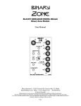
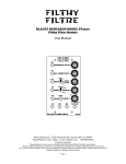
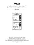
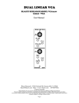
IO
BLACET RESEARCH MODEL IO2225
Input Processor Module
User Manual
Blacet Research 15210 Orchard Rd Guerneville CA 95446
[email protected] http://www.blacet.com 707-869-9164
Contents Copyright.
Reproduction by any means including the Internet prohibited without permission.
This document contains proprietary and trade secret information of Blacet Research and is provided
as a service to the module owner. Any unauthorized duplication or transferral may violate trade secret laws.
Contents subject to change without notice.
Page 1
Introduction
The IO2225 is a versatile input signal processor module designed to amplify signals from a wide variety of sources
to standard modular levels of 10V p-p. In addition, a 5V power source is included on the 1/4” Input jack to allow
the easy integration of foot pedals, pressure sensors, etc.
The X10 range of the amplifier is DC coupled, allowing for the processing of control voltages.
The envelope of the input signal is available at two outputs with attenuators; with a lag control for the second
output.
A comparator with a level control monitors the envelope and extracts Gate and Trigger information to initiate events
on other modules.
Input: 3.5mm Jack
Gain
Output
Input: 1/4” Stereo Jack
(5V available on ring or tip)
Amplifier Gain Range
X10 = DC Coupled
X100, X500 = AC Coupled
Envelope #1 Output
Envelope #1 Attenuator
Envelope #2 Output
Envelope #2 Attenuator
Envelope #2 Lag
Gate LED
Gate/Trigger Trip
Level
Gate and Trigger
Outputs
Page 2
Controls and Operation
Input Jacks, Output Jack, Gain Pot, Range Switch (X10, X100, X500): Before plugging in an external signal, turn
the Gain control down and set the Range switch to the minimum required. For example, a line level signal from a
keyboard or consumer audio product would need the X10 setting. A non preamped guitar or microphone might
require the X100 or X500 setting. Note that the X10 position is DC coupled with low offset voltages, so control
voltages can be easily processed.
For the X100/X500 setting, avoid turning the Range pot full CW without a signal input as oscillation may occur.
Connect the Out jack to any other module as required; for example the Final Filtre.
The 1/4” input is a stereo jack, allowing for an internal +5V power supply to be connected to external devices. In
the standard factory configuration, the +5V is placed on the ring of a stereo input plug, although DIP switches (S2)
on the IO PCB allow the user to assign the signal and power functions to either the tip or ring of the stereo plug.
In general, we would advise using the factory settings for S2 as this allows most inputs without having to change the
switch settings. For example, using a mono plug for the input, the +5V out sees common and is shut off by internal
sensing circuitry. Using a stereo plug places the +5V on the ring of the plug for use with a pedal, etc. Some pedals
switch the tip and ring so the option is there on the DIP switch. It may be more convenient, however, to rewire the
plug of the pedal if you intend to use it only for the module.
The standard input impedance of the module is 100K, although this can be changed via IO PCB DIP switch S3 to
470K for use with weak signals such as those from a guitar or mike. This may improve high frequency response.
The second section of S3 allows for the disabling of the automatic switching to AC coupling for the X100/X500
ranges. This should be left in the “AC” position unless you are attempting to amplify very small DC signals.
As mentioned above, S2 allows for the configuration of the 1/4” Input jack. (As the two input jacks share a
common input to the amplifier section, note that these settings may also effect the 3.5mm Input jack).
PCB DIP Switch Functions
Env 1 Atten Pot, Env 2 Atten Pot , Env 2 Lag Pot, Output jacks: An envelope follower converts the amplified
signal to DC and applies low pass filtering to derive a DC voltage proportional to audio level (envelope). This is
useful for controlling other modules. Each of the two outputs can be attenuated. The Env 2 output has additional
low pass filtering or lag to delay the response of the voltage in relationship to the Env 1 output. These delays are in
the 0 to 2 second range.
Gate, LED, Trig Outputs, Level Pot: By comparing the level of the envelope with a setpoint determined by the
Level pot, a Gate signal is generated. A trigger pulse is also derived from the leading edge of the gate signal.
Power Input Jack J8: A source of regulated +/-15Vdc power must be supplied to this PCB jack to run the module.
Note the current requirements in the “Specifications” section.
Connections to this jack should be made only when the power supply is OFF and the connector must be
positioned correctly on the pins. As using the wrong supply can cause damage to the unit, please contact us if you
have any questions! Do not attempt to use “wall warts” to power the module.
Page 3
Specifications
Front Panel Size: 5.25 x 3" W
Module Depth: 5.6”
Input/Output Jacks: 3.5 mm (1/8”); one Input jack is stereo 1/4” with optional power out.
Powered Jack: +5V regulated @ 25 mA max; short circuit protected
Gain Range: 0-500
Frequency Range: 0 to 20 KHz
Envelope Outputs: 0-10V
Gate: 10V
Trigger: 10V/5mS
Output Level: +/-13.5V max
Power: +/-15 Vdc @+35/-35 mA
Calibration
Remove any inputs from the module and turn the Gain pot FCCW. Select the “X500” gain setting. Connect a DMM
to common at the left side of D6 and the red lead to TP1. Set the DMM to read millivolts. Adjust RT1 to zero volts.
Repeat the procedure using TP2 and RT2.
Troubleshooting, Repair, Warranty
If you encounter problems that you can’t solve, contact us, preferably via e-mail with a description of the problem.
Let us know what does and does not work. We can then help you get your module working. We can fix modules for
a minimum fee of $25.
The parts contained in this unit have been carefully selected and tested. They are guaranteed for 90 days from the
date of purchase. If you believe that you have a defective part (or if you have a part missing), contact us so we can
provide you with a replacement or repair.
Page 4
Front Panel Wiring
J1
6.7”
1.7
J2
1.7
6.7”
2.4
1.7
J3
6.0
J4
2.2
J5
2.2
2.3
COM
J7
J6
5
6
1.7
8.5 strip 2.5
1
2
3
4
Page 5
7