1
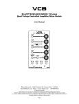
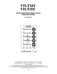
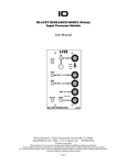
DUAL LINEAR VCA
BLACET RESEARCH MODEL VCA2410
Linear VCA
User Manual
Blacet Research 15210 Orchard Rd Guerneville CA 95446
[email protected] http://www.blacet.com 707-869-9164
Contents Copyright.
Reproduction by any means including the Internet prohibited without permission.
This document contains proprietary and trade secret information of Blacet Research and is provided
as a service to the module owner. Any unauthorized duplication or transferral may violate trade secret laws.
Contents subject to change without notice.
Page 1
Introduction
The VCA2410 is a dual, linear response voltage controlled amplifier (VCA). Both VCAs may be used
independently or together to process audio or control voltages.
The two CV inputs are normalled to an internal voltage source so that the VCAs can be used in mixer mode without
any external CV. When a patch cord is plugged into a CV jack, the internal CV is bypassed.
Normalling also routes the A input to the B input and the B output to the A output. The “Controls and Operation”
section will show why this is a handy feature.
One control knob is available for each VCA. Note that they may yield the same results, but that each one has a
distinct function. The upper control attenuates the input signal, while the lower control attenuates the CV. This
allows added flexibility in use.
“A” Signal Attenuator
“A” (“B”) Signal Input
(Also sent to “B” if “In B” is
not connected)
“A” Control Voltage
“A” (“B”) Signal Output
(Includes “B” Signal if “Out B”
is not connected)
“B” CV Attenuator
“B” Signal Input
“B” Control Voltage
“B” Signal Output
Page 2
Controls and Operation
IN A(B), OUT A(B), CV A, SIG ATTN Pot: The 2410 has two VCA sections. A signal applied to In A(B) will
appear at Out A(B). The signal level will be determined by the setting of the Sig Attn (signal attenuation) pot and
the level of any external control voltage input at CV A.
With no plug present at the CV A jack, an internal 10V source is connected to the circuit, allowing 100% output.
The control voltage range is 0-10V with a linear response. A level of 0 volts results in no output, a level of 5V allows
an output of 50% of the input (assuming the Sig Attn pot is FCW), and 10V results in 100% output. There is no gain
associated with the VCA.
IN B, OUT B, CV B, CV ATTN Pot: The second section of the 2410 operates in a similar manner, except for the
presence of jack normalling. If nothing is plugged into In B, then the In A(B) signal will be connected internally to the
B VCA. This allows splitter and panner functions without external multiples.
If nothing is plugged into Out B, then the Out B signal will be summed internally with the A signal and appear at the
Out A(B) jack. This allows mixer and VC fader functions without an external mixer.
The diagrams below illustrate some typical configurations.
For VC stereo panning, use the “Splitter” configuration with a source of normal (0-10V) and inverted CVs (10-0V)
(such as the Blacet EG1) connected to the CV ins.
For a VC fader, use the “Mixer” configuration and a CV source as in the “Splitter” mode.
Splitter
IN
OUT
A
Mixer
IN
CV
IN
IN
CV
IN
CV
OUT
B
OUT
A
CV
OUT
B
OUT
A
Independent VCAs
CV
IN
OUT
B
CV
Power Input Connector J7: This PCB connector requires a source of regulated +15Vdc and -15Vdc power to run the
module. Use a Blacet PS500 supply or the equivalent.
Connections to J7 should be made only when the power supply is OFF and the connector must be positioned
correctly on the pins. As using the wrong supply can cause damage to the unit, please contact us if you have any
questions! Do not attempt to use “wall warts” to power the module.
Safety Information
The use of any audio equipment requires some care to avoid potential damage to the hearing of the operator or their
audience. Even short term exposure to high audio levels can lead to temporary hearing loss and ringing in the ears.
Repeated exposure can eventually lead to permanent hearing problems.
Your ears have to last you all your life; take a few precautions to keep them happy so that you can enjoy music even
when you are older!
• When using mid to high volume levels, be aware that the ear will loose sensitivity at some point, causing you
to turn up the volume to compensate. In an extended session, this can happen repeatedly, until the volume is
quite high and potentially dangerous.
• Break up sessions into half hour segments; avoid “all night” jams.
• Take breaks often and choose a maximum volume setting for “mandatory” breaks.
• Try using very, very low volumes as a break.
• Music can sound quite different at low levels; use low volumes for initial setup and routine practice, saving
high levels for final mixes.
• If your music starts to sound “painful”, it’s most likely causing hearing damage as well!
Page 3
Specifications
Front Panel Size: 5.25 x 1.5" W
Module Depth: 3.2”
Input Gain: 1X max
CV Range: 0-10V
Frequency Range: DC to 20 KHz
Signal Level: typ. 10V p-p, Max: 26V p-p
Power: +/-15 Vdc @+35/-35 mA
1.8
J2
4
1.4
1.8
J5
3.5
1.4
COM
1
2
3
4
5
6
7
Calibration
Calibration is not required.
Troubleshooting, Repair, Warranty
If you encounter problems that you can’t solve, contact us, preferably via e-mail with a description of the problem.
Let us know what does and does not work. We can then help you get your module working. We can fix modules for
a minimum fee of $25.
The parts contained in this unit have been carefully selected and tested. They are guaranteed for 90 days from the
date of purchase. If you believe that you have a defective part (or if you have a part missing), contact us so we can
provide you with a replacement or repair. Include your name and invoice number.
Page 4