1
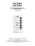
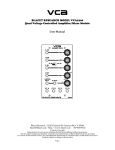
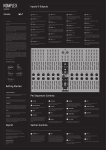
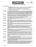
BINARY
Zone
BLACET RESEARCH MODEL BZ2300
Binary Zone Module
User Manual
Blacet Research 15210 Orchard Rd Guerneville CA 95446
[email protected] http://www.blacet.com 707-869-9164
Contents Copyright.
Reproduction by any means including the Internet prohibited without permission.
This document contains proprietary and trade secret information of Blacet Research and is provided
as a service to the module owner. Any unauthorized duplication or transferral may violate trade secret laws.
Contents subject to change without notice.
Page 1
Introduction
The BZ2300 is a versatile clocked CV producing module that is part sequencer, part frequency divider and part gate
generator. Complex CV patterns of up to 64 steps, ranging up to +/-10V in amplitude can be easily generated with
the module’s unique user interface, consisting of only six step control knobs.
The BZ was inspired by the popular “Digital Pattern Generator” from Blacet’s early days, a module that was a
contruction project in Synapse magazine, a kit and was also incorporated into the Blacet “Phasefilter” module. The
BZ is a vastly improved version with six bits of binary versus four, bipolar controls, a lag processor, versatile
clocking options, normal and inverted outputs and a range switch.
Use the Binary Zone to control any module CV input such as a VCO, VCA, VCF, or the Mini Wave. Try the BZ with
a quantizer function such as the MW to get precise CVs for note sequences from your VCO. Use the BZ to divide
external waveforms via the “Clock In” for audio or gate generation.
Adds ÷2 pulses to output
mix. +/- control, center off
Internal Clock
Clock LED
External Clock Input:
Overrides internal clock;
accepts almost any waveform
Adds ÷4 pulses to output
mix. +/- control, center off
Clock Outputs
Follows internal or external
clock with square and pulse
outs
Adds ÷8 pulses to output
mix. +/- control, center off
Output
Adds ÷16 pulses to output
mix. +/- control, center off
Lag: three settings and off
Output Range Switch
+/-2V, +/-10V, +/-5V
Adds ÷32 pulses to output
mix. +/- control, center off
Inverted Output
Inverts around common
Gate and Reset Input
Normalled “On”
Auto resets sequence with Gate
Adds ÷64 pulses to output
mix. +/- control, center off
Page 2
Controls and Operation
Internal Clock Pot, Clock LED, External Clock Input, Clock Outputs: The internal clock has a range of 1S to
20Hz; suitable for CV sequence generation. Plugging in an external clock allows for operation up into the audio
range. Almost any waveform of sufficent amplitude (5V, typ.) can drive the module, allowing for frequency divider
functions and control via almost any audio or clock producing module.
The Clock Outs follow the internal or external clocks with square and pulse outputs. This allows the BZ to be used
as the master controller.
÷2 thru ÷64 Pots: The BZ functions as a six bit binary counter with the output stages connected to the six pots.
These pots serve as a digital to analog converter with the ability to add or subtract the square wave outputs of the
counter in any quantity to the output mix.
Try connecting the BZ to a VCO frequency control input. If you center all the pots and then turn each one up (or
down) in turn, starting at the top, you will notice that each pot controls a square wave that is 50% slower at each
stage. Try using two pots at once, then three, then four. You will notice that the simple square waves soon become
quite complex up and down staircases.
This is the power of the BZ: complex sequences with only six controls. It is also the “frustration” of the BZ, because
it is not possible to precisely control each step. The frustration, however, can be the fun aspect of the BZ: you are
free to twirl the knobs and locate the treasures without regard to the “rules” of music!
Output Range Switch: This switch allows the maximum output level of both the normal and inverted outputs to be
set to +/-2V (X1), +/-5V (X2.5), or +/-10V (X5). You may find the X1 more useful when controlling a VCO as the
other two settings may result in frequencies out of hearing range. There is also more pot resolution in the X1 position.
Output, Inverted Output: The inverted out is a negative voltage copy of the output. For example, a simple square
wave out of the normal output of 0 to +5V would result in an output of 0 to -5V on the inverted out.
Lag Pushbutton: The lag button provides three levels of lag and “off” or no lag. Lag allows interesting glide effects
between sequence steps. Using maximum lag allows more subtle control voltage outs with little evidence of “steps”.
The lag circuit has a memory function that holds the last position if the power to the module is lost temporarily.
Gate/Reset Input: This input turns the counter on and off and resets the sequence. It does not affect the clock, so
you will still see the clock LED blinking and the clock outs will still function, even if the gate input is low (common).
This input is normalled “on” via the switching jack so that no input is required for the BZ to function. Inserting a
plug will cause the BZ counter to repond to any gate signal. A “high” (>1V) will reset the counter and start the
sequence running.
Power Input Connector J7: This PCB connector requires a source of regulated +15Vdc and -15Vdc power to run the
module. Use a Blacet PS500 supply or the equivalent.
Connections to this connector should be made only when the power supply is OFF and the connector must be
positioned correctly on the pins. As using the wrong supply can cause damage to the unit, please contact us if you
have any questions! Do not attempt to use “wall warts” to power the module.
Specifications
Front Panel Size: 5.25 x 3" W
Module Depth: 6.1”
Input/Output Jacks: 3.5 mm (1/8”)
Internal Clock Frequency Range: 1S to 20 Hz
External Clock Frequency Range: 0 to 20 KHz
Clock Outputs: 0-15V
Gate Level: >1V
Output Level: +/-10V max
Power: +/-15 Vdc @+30/-15 mA
Calibration
Trimmers RT1 thru RT6: These set the center “off” position of the six front panel pots to as close to zero volts as
possible. The fastest method is to insert an external clock or VCO running at audio frequencies and monitor the BZ
Out via mixer or amp. Set the Range to X1, the Lag to “off” and be careful with the volume (if you don’t hear
Page 3
anything, the Lag is probably “on”).
Turn all six front panel pots to the center detent. Adjust each trimmer for minimum audio out, noting that each pot is
spaced one octave apart. When you achieve maximum quiet, you are done.
Troubleshooting, Repair, Warranty
If you encounter problems that you can’t solve, contact us, preferably via e-mail with a description of the problem.
Let us know what does and does not work. We can then help you get your module working. We can fix modules for
a minimum fee of $25.
The parts contained in this unit have been carefully selected and tested. They are guaranteed for 90 days from the
date of purchase. If you believe that you have a defective part (or if you have a part missing), contact us so we can
provide you with a replacement or repair. Include your name and invoice number.
Page 4
R7
3”-3X
1
J1
2.5
6.2
2.7
J2
2.1
6.3
J3
1.5
6.1
COM
4.2”-3X
S1
J4
3
2
1
2.1
J5
7.3
(.9)
2.1
2.1
J6
2.3
7
1
2
3
4
Page 5
5
6
7