1
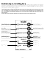
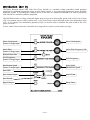
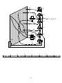
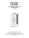
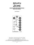
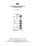
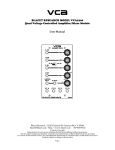
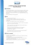
DARK STAR
CHAOS
BLACET RESEARCH MODEL DSC2000
Voltage Controlled Sound Synthesizer
User Manual
Blacet Research 15210 Orchard Rd Guerneville CA 95446
[email protected] http://www.blacet.com 707-869-9164
Contents Copyright.
Reproduction by any means including the Internet prohibited without permission.
This document contains proprietary and trade secret information of Blacet Research and is provided
as a service to the module owner . Any unauthorized duplication or transferal may violate trade secret laws.
Contents subject to change without notice.
Page 1
Introduction (Up to and including Rev A)
The Blacet Research Model 2000 Dark Star Chaos Module is a modular voltage controlled sound generator
optimized for producing an unusual variety of noise based sounds. A very wide range digital noise source and filter
modulates a pulse VCO, making this a unique device. It can serve as a stand alone module or be used in conjunction
with old and new modular synthesis equipment.
The DSC2000 includes a voltage controlled digital noise source clock allowing the speed of the noise to be set from
“Off” to a random step to a rush of white noise. A VC Noise Filter controls the depth of the noise modulation of the
VCO. A VC triangle wave modulation generator (LFO) can also be used to modulate the pulse width of the VCO
pulse waveform.
A basic Attack/Decay Generator and audio level stage allows control over the audio envelope.
Noise Clock Speed
Control Voltage Input
Noise Clock Speed
Noise Filter
Control Voltage Input
Noise Filter Frequency (LP)
VCO Frequency
Control Voltage Input
VCO Frequency
Modulation Speed
Control Voltage Input
Pulse Width
Modulation Speed
Gate Control Input
Attack Time
Gate Button
Decay Time
Signal Output
Page 2
Controls and Operation
Noise Clock: The Dark Star uses a digital “psuedorandom” noise source that can be clocked. An advantage of this
type of noise is that it’s speed can be adjusted, allowing effects from random stepped sequences, vibrato, modem
type noises, robot data, on up to all kinds of typical noise events like surf, water, wind, etc. The Clock control can
also go to “Off” which means that only the pure sound of the VCO will be heard.
Noise Filter: This is a simple LP or Low Pass filter that controls the amount and frequency of the noise sent to the
VCO. At the lowest setting, no noise will reach the VCO. At higher settings, the VCO will start to take on some of the
character of the noise modulation. At higher settings the sound of the DSC will contain more of the noise modulation.
VCO: The Voltage Controlled Oscillator has one waveform, a variable pulse width type. Fortunately this is one of
the more interesting waveforms available on a simple VCO. The wave is modulated by the noise source and the PWM
or Pulse Width Modulation control covered below. The simple nature of this VCO precludes accurate frequency
tracking from an analog keyboard or MIDI-CV convertor. A simple analog sequencer can be used however for
accurate note tuning, since this type of device can output any required voltage.
PWM: This controls the speed of a triangle wave LFO or Low Frequency Oscillator which is coupled to the PWM
input of the VCO. This will produce a wide variety of harmonics in the output waveform. Near the CW limit of the
PWM control rotation, a bit of change in the VCO frequency will also be noted.
Attack, Decay, Gate Jack, Gate Pushbutton: The audio output level or envelope of the sound is controlled via a
function generator which is “Gated” or turned on by the Gate Input or the Gate Pushbutton. The waveform at the
Gate jack should be a 5V or greater square wave or other rapidly rising waveform. Slowly changing waveforms will
not start the function generator.
The time that the audio level takes to reach maximum loudness is controlled by the Attack control, with time being
greater as you turn the control CW.
Once the Gate signal is removed, the time the sound takes to reach silence is controlled by the Decay control.
Power Input Jack J7: The DSC has on-board voltage regulators which allow it to be powered by a variety of DC
voltage sources. The standard supply is regulated +/-15VDC . +/-12VDC is also permitted.
The on board regulators are +8V and -5V. Allowing for a minimum of a 2V input-output differential, the minimum
plus voltage would be 10V, the minimum minus voltage 7V. Voltages in excess of 18VDC, regulated or unregulated
are not recommended.
Connections to this jack should be made only when the power supply is OFF and the connector must be
positioned correctly on the pins.
As using the wrong supply can cause damage to the unit, please contact us if you have any questions!
Introduction (Rev B)
Page 3
Introduction (Rev B)
The Blacet Research Model 2000 Dark Star Chaos Module is a modular voltage controlled sound generator
optimized for producing an unusual variety of noise based sounds. A very wide range digital noise source and filter
modulates a pulse VCO, making this a unique device. It can serve as a stand alone module or be used in conjunction
with old and new modular synthesis equipment.
The DSC2000 includes a voltage controlled digital noise source clock allowing the speed of the noise to be set from
“Off” to a random step to a rush of white noise. A VC Noise Filter controls the depth of the noise modulation of the
VCO. A VC triangle wave modulation generator (LFO) can also be used to modulate the pulse width of the VCO
pulse waveform.
A basic Attack/Decay Generator and audio level stage allows control over the audio envelope.
Noise Clock Speed
Control Voltage Input
Noise Clock Speed
Noise Filter
Control Voltage Input
Noise Filter Frequency (LP)
Filtered Noise Out
VCO Frequency
Control Voltage Input
VCO Frequency
Modulation Speed
Control Voltage Input
Pulse Width
Modulation Speed
Gate LED
Gate Control Input
Attack Time
Gate Switch
Signal Output
Decay Time
Page 4
Controls and Operation
All CV Inputs are designed for 5V operation. (0 to +5V or 0 to -5V with the pot FCW). The VCO CV Input also
responds to audio frequencies.
Noise Clock: The Dark Star uses a digital “psuedorandom” noise source that can be clocked. An advantage of this
type of noise is that it’s speed can be adjusted, allowing effects from random stepped sequences, vibrato, modem
type noises, robot data, on up to all kinds of typical noise events like surf, water, wind, etc. The Clock control can
also go to “Off” which means that only the pure sound of the VCO will be heard.
Noise Filter: This is a simple LP or Low Pass filter that controls the amount and frequency of the noise sent to the
VCO. At the lowest setting, no noise will reach the VCO. At higher settings, the VCO will start to take on some of the
character of the noise modulation. At higher settings the sound of the DSC will contain more of the noise modulation.
Noise Out: The filtered noise is available at this jack. With the filter at FCW, the noise amplitude varies from +/-5V
at slow noise clock speeds to +/-2.5V at maximum speed. This output is on continuously and is not effected by the
Gate input.
VCO: The Voltage Controlled Oscillator has one waveform, a variable pulse width type. Fortunately this is one of the
more interesting waveforms available on a simple VCO. The wave is modulated by the noise source and the PWM or
Pulse Width Modulation control covered below. The simple nature of this VCO precludes accurate frequency tracking
from an analog keyboard or MIDI-CV convertor. A simple analog sequencer can be used however for accurate note
tuning, since this type of device can output any required voltage.
PWM: This controls the speed of a triangle wave LFO or Low Frequency Oscillator which is coupled to the PWM
input of the VCO. This will produce a wide variety of harmonics in the output waveform. Near the CW limit of the
PWM control rotation, a bit of change in the VCO frequency will also be noted.
Attack, Decay, Gate Jack, Gate Switch: The audio output level or envelope of the sound is controlled via a function
generator which is “Gated” or turned on by the Gate Input or the Gate Switch. The waveform at the Gate jack should
be a 5V or greater square wave or other rapidly rising waveform. Slowly changing waveforms will not start the
function generator. The Gate switch allows for a momentary gate, external gate or continuous gate (always on).
The time that the audio level takes to reach maximum loudness is controlled by the Attack control, with time being
greater as you turn the control CW.
Once the Gate signal is removed, the time the sound takes to reach silence is controlled by the Decay control.
Power Input Jack J8: The DSC standard supply is regulated +/-15VDC . Connections to this jack should be made
only when the power supply is OFF and the connector must be positioned correctly on the pins.
As using the wrong supply can cause damage to the unit, please contact us if you have any questions!
Page 5
2.1”
J1
J2
2.5”
J3
2.5”
J4
2.5”
8.5”, strip 3.1”
3.2”
J5
J6
3.9”
5.5”
Page 6
1.9
J1
2.5
J2
J3
8.5”, strip 3.1”
3.1
J4
2.5
J5
2.5
4.2
S1
COM
J7
3.5
5.6
2
J6
3
2
1
5.3
1
6.0
3
4
Page 7
5
6
7
Calibration
There are no calibration points on this board.
Troubleshooting, Repair, Warranty
If you encounter problems that you can’t solve, contact us, preferably via e-mail with a description of the problem.
We can then help you get your module working.
The parts contained in this unit have been carefully selected and tested. They are guaranteed for 90 days from the
date of purchase.
Specifications
Front Panel Size: 5.25 x 3" W
Module Depth: 5”
Input/Output Jacks: 3.5 mm (1/8”)
Gate Input Level: 5 V step*
CV Range: 0-5V *
VCO Range: 0-6.5 KHz (linear response)***
VCO Waveform: pulse with width modulation
Noise Clock Range: 0 Hz-32 KHz
Attack/Decay Time: up to 12 S
Output Level: 1.2 V**
Power: +/-12 to +/-15 Vdc @+25/-11 mA
*All inputs will tolerate +/-15 V
**Up to 3 V with resistor change
***Not recommended for accurate keyboard tracking applications
Page 8