1
DRAFT
CHAPTER 8
ASTRONOMY FOR MARINE ARTILLERY
Marine artillery surveyors are required to provide an azimuth to the supported unit, or to
determine a starting azimuth for conventional survey. If an azimuth is not provided in a Trig
list, or cannot be computed, the surveyor can establish an azimuth by performing observations
of celestial bodies.
Section I
BASIC ASTRONOMY
8-1 The Tilted Polar Axis and Movement
of the Earth
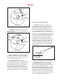
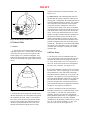
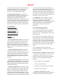
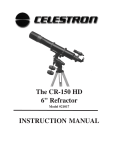
a. The Earth's Tilted Axis. The Earth can best be
visualized as an ellipsoid. The line connecting the
flattened ends or the shorter axis is the Earth's
rotating axis. The points on the Earth where this axis
intersects the surface are the north and south poles;
therefore, the rotating axis is also referred to as the
polar axis. If the Earth's polar axis were
perpendicular to its orbit around the Sun, there would
be no change in seasons; the Sun's rays would always
be directed at the equator. Because the Earth's axis is
tilted at an angle of approximately 23° 30' (417.78
mils), the Sun's rays are directed at different portions
of the Earth as it orbits the Sun. (See Figure 8-1)
23° 30'
Axi
s
rth
Ea
Figure 8-1
2. Rotation. The Earth makes one 360° rotation
on its axis every 23h 56m 04.091s. The rotation is
from west to east; therefore, because of revolution,
the Earth must rotate more than 360° for the same
point to face directly at the sun on subsequent days.
(See Figure 8-1.)
3. Revolution. The Earth revolves around the Sun
once every 365 days (approx.) over a 600 million
mile orbit at a rate of 18.5 miles per second. The
counter- clockwise orbit is elliptical with an average
distance to the Sun of about 93 million miles.
4. Other types of motion affect the Earth. For
instance, the north and south poles are not stationary;
they vary through rough circles approximately 40 feet
in diameter. Also, there is solar motion of 12 miles
per second, while the Earth's portion of the galaxy is
moving through space at approximately 170 miles per
second.
Ear
th's
Ea
rth
's R
ota
tion
1. Precession. The Earth's axis has a cone-shaped
motion, or precession, making one turn in 25,800
solar years or, one platonic year (great year). This is
caused by torque imposed on the Earth mostly by the
Moon and Sun. It can be visualized as a spinning top;
as the spinning slows, the top begins to wobble
creating a cone-shaped motion in its rotating axis.
Earth's Rotational Axis
b. Movement of the Earth. The Earth and its
motions are of primary interest to the artillery
surveyor. These motions form a complex pattern, all
of which affect the Earth's relationship to the stars
and other planets.
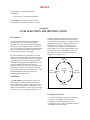
8-2 Celestial Sphere
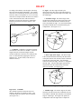
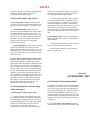
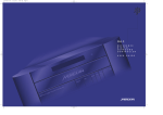
a. General. For purposes of practical astronomy, we
assume that the Earth is at the center of the Universe,
and that everything else (i.e. Sun, stars, planets, etc.)
falls on the surface of a sphere of infinite radius
referred to as the Celestial Sphere. We also assume
that the Earth is stationary and that the celestial
sphere rotates around the Earth from east to west.
This is because the Earth rotates west to east
DRAFT
(counterclockwise), so the apparent motion of
celestial bodies is the opposite direction. (See Figure
8-2.)
les
Ce
l
tia
he
Sp
Celestial
North Pole
re
23° 30'
Ap
pa
ren
M o t C el
tio esti
al
n
Earth
Celestial Equator
Celestial
South Pole
Figure 8-2
Celestial Sphere
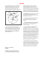
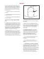
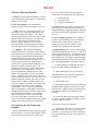
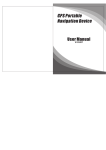
d. Zenith Position. The position of the observer on
the surface of the Earth is located by latitude and
longitude. When the observer's plumb line is
extended upward to the celestial sphere, a point
referred to as the observer's zenith or the zenith
position is established. The zenith position is also
located by latitude and longitude and provides a fixed
position of the observer's instrument on the celestial
sphere. The zenith latitude is the arc distance from
the celestial equator to the observer's zenith. The
zenith longitude is the arc distance along the celestial
equator from the plane of the Prime Meridian
(Greenwich Meridian) to the plane of the observer's
meridian extended to intersect the celestial sphere.
Zenith longitude is also the angle between those two
planes as measured at the celestial poles. (See Figure
8-3.)
Ob
Observer's
Zenith
Zenit
h
Lon
gitud
e
Zenith
Latitude
ere
Sph
c. Observer's Meridian. The observer's meridian is
an hour circle that includes the plane of the observer's
n
al
esti
Cel
b. Great Circle/Hour Circle. Any circle on the
surface of the celestial sphere whose plane passes
through the center of the celestial sphere is called a
great circle. For example, the celestial equator is a
great circle. When that plane is set perpendicular to
the celestial equator it is referred to as an hour circle
and includes both poles of the celestial sphere.
a
idi
er
Observer's
Position
8-3 Celestial Coordinates
a. General. Computations of astronomic
observations are performed in part using the celestial
coordinates of points on the celestial sphere. Since
these coordinates are located on the surface of a
sphere, they are referred to as spherical coordinates.
In general, there are two systems of spherical
coordinates: the horizon system and the equator
system. For artillery survey methods, the equator
system is used.
v
ser
M
's
er
Figure 8-3
ich
reenw
tial G
Celes eridian
M
b. Celestial Poles and Equator. The celestial
sphere rotates around the stationary Earth on an axis
that coincides with the polar axis of the Earth. The
locations of the celestial poles are at the point in the
sphere where the Earth's polar axis would intersect
the sphere if they were extended into space. If the
plane of the Earth's equator was extended into space,
the point where that plane intersects the celestial
sphere is the celestial equator. (See Figure 8-2.)
longitude. The upper transit of the observer's
meridian is that part which includes the observer's
longitude and the observer's zenith (the observer's
plumb line extended upward to the celestial sphere).
The lower transit of the observer's meridian is 180°
from the upper transit and includes the observer's
nadir (the observer's plumb line extended downward
to the celestial sphere).
Celestial Equator
Zenith Position
e. Prime Vertical. The prime vertical for the
position of an observer is a great circle on the
celestial sphere that is perpendicular to the observer's
meridian at the zenith and intersects the observer's
horizon at points due east and west of the observer.
f. Star Position. The position of a star on the
celestial sphere is defined in terms of Right
Ascension and Declination.
DRAFT
1. Right Ascension (RA).
a. As the Sun moves across the celestial sphere it
traces a path referred to as the ecliptic. The ecliptic
is tilted approximately 23° 30' (417.78 mils) from the
celestial equator due to the tilt of the celestial sphere
on its axis. It crosses the celestial equator at two
points along its path. The point where the ecliptic
crosses the celestial equator from the southern
hemisphere to the northern hemisphere is the Vernal
Equinox, the first day of spring usually around
March 21. (See Figure 8-4.)
b. Right Ascension (RA) is the arc distance
eastward along the celestial equator measured from
the vernal equinox to the hour circle of a celestial
body. In most cases, RA is expressed in terms of arc
time (i.e. hours: h, minutes: m, and seconds: s). It can
vary from 0h to 24h east of the vernal equinox. (See
Figure 8-5.)
seconds ("). It can be expressed in terms of mils.
Declination can vary from 0° to 90° north or south of
the celestial equator. (See Figure 8-5.)
8-4 Astronomic Triangle (PZS Triangle)
a. General. The determination of an astronomic
azimuth is dependent upon the solution of a spherical
triangle located on the surface of the celestial sphere.
This triangle is referred to as the PZS triangle. The
method of astronomic observation determines the
sides and vertices of the triangle to be solved.
b. Vertices. The PZS triangle has vertices at the
celestial North Pole, at the observer's Zenith, and at
the Star (or Sun). These vertices are the intersections
of great circles that include the triangle's sides.
(See Figure 8-6.)
Celestial
North Pole
P
Celestial Sphere
Observer's
Zenith
Vernal Equinox
Celestial Equator
Sun
Celestial
Body
Z
S
Observer's
Meridian
Hour Circle of
Celestial Body
23° 30'
Observer's
Position
Celestial E
Ecliptic
quator
Autumnal Equinox
Celestial Sphere
Figure 8-4
Ecliptic and Vernal Equinox
Figure 8-6
Vertices of the PZS Triangle
Star's
Hour Circle
Celestial Equator
DEC
Earth
Vernal Equinox
RA
Celestial Sphere
Figure 8-5 Right Ascension and Declination
2. Declination (Dec). Declination is the arc
distance measured from the celestial equator to the
body along the hour circle of the star. It can be north
(+) or south (-) of the celestial equator and is usually
expressed in terms of degrees (°), minutes ('), and
c. Sides. The sides of the PZS triangle are segments
of great circles passing through any two of the
vertices. Therefore, the sides are arcs and as such are
measured with angular values. The three sides of the
triangle are the Polar Distance, the Coaltitude, and
the Colatitude.
1. Polar Distance. Polar distance is a segment
of the hour circle of the celestial body. It is the arc
length of the side of the PZS triangle from the
celestial North Pole to the celestial body (the PS
side). It is determined by applying the celestial
body's declination to 90°. In other words, if the
declination is north (+), the polar distance equals 90°
minus the declination; if the declination is south (-),
the polar distance equals 90° plus the declination.(See
Figure 8-7.)
DRAFT
P
Polar
Distance
Cele
stia
l
Equ
ato
Celestial
North Pole
S
Celestial
Body
Hour Circle of
Celestial Body
r
Figure 8-9
Celestial Sphere
Figure 8-7
Polar Distance
2. Coaltitude. Coaltitude is the arc length of the
side of the PZS triangle from the celestial body to the
observer's zenith.
Coaltitude
Observer's
Zenith
Observer's
Meridian
Celestial
Body
Z
S
Cele
stial
Equ
ato
Hour Circle of
Celestial Body
r
Determining Coaltitude
c. Parallax. Parallax can be defined as the
apparent displacement of a body on the celestial
sphere caused by a change in position of the observer.
In other words, the observed altitude, or vertical
angle, of a celestial body must be corrected for the
error introduced by the observer's location on the
surface of the Earth vice the center of the Earth. The
12
nearest star is 26 x 10 miles from Earth; the Sun is
6
only 93 x 10 miles from Earth; because the stars are
so distant the apparent displacement of the stars is
nearly immeasurable. For this reason, parallax
corrections are used for observations on the Sun only.
Parallax on the Sun varies from +9" when the it is on
the observer's horizon (vertical angle 0 mils) to 0"
when it is on the observer's meridian. For artillery
survey, a constant value of +7" (0.04 mils) is used.
(See Figure 8-10.)
SUN
Celestial Sphere
Figure 8-8
Coaltitude
a. Observer's Horizon. The observer's horizon is
a plane that is tangent to the surface of the Earth at
the observer's position; it is also perpendicular to the
observer's zenith. See Figure 8-9.
OBSERVER
CENTER
OF EARTH
Figure 9-10
b. Determining Coaltitude. Coaltitude is
determined by subtracting the vertical angle (altitude)
of the celestial body from 90° (1600 mils). This
vertical angle must be corrected for refraction and
parallax for sun observations and corrected for
refraction for star observations. The resultant angle is
side ZS of the PZS triangle and can be referred to as
the zenith angle of the celestial body. (See Figure 89.)
Parallax
d. Refraction. Refraction can be defined as the
apparent displacement of a body on the celestial
sphere caused by the deflection of light rays as those
rays pass through the Earth's atmosphere. A ray of
light passing through the Earth's atmosphere at a large
angle of incidence, (the angle formed by the line of
the light ray and a line which is perpendicular to the
atmosphere), will have a larger refraction correction
than a ray of light passing through an area close to the
observer's zenith. Refraction of a body varies
DRAFT
according to the altitude (vertical angle) of the body
above the horizon and the temperature. For example,
refraction of a celestial body located on the observer's
horizon (0 mils) at a temperature of 70° is 10.26 mils;
refraction of a body located on the observer's zenith is
0 mils. Refraction increases with an increase in
barometric pressure and a decrease in temperature.
Refraction corrections are always negative. (See
Figure 8-11.)
OBSERVED
CELESTIAL
BODY
d. Angles. The three angles formed by the
intersection of the three sides of the PZS triangle are
the parallactic angle, the hour angle (time angle), and
the zenith angle.
1. Parallactic Angle. The interior angle at the
celestial body formed by the intersection of the polar
distance side (PS side) and the Coaltitude side (ZS
side) is the parallactic angle. It is used in determining
astronomic azimuths but is canceled out during the
computations. (See Figure 8-13.)
Celestial
North Pole
P
ACTUAL
CELESTIAL
BODY
ATMOSPHERE
Paralactic
Angle
Observer's
Zenith
Z
OBSERVER
S
Celestial
Body
EARTH
Celestial Eq
uator
Figure 8-11
Refraction
3. Colatitude. Colatitude is a segment of an hour
circle known as the observer's meridian. It is the arc
length of the side of the PZS triangle from the
celestial North Pole to the observer's zenith (the PZ
side). It is determined by applying the observer's
latitude to 90°. In other words, if the observer's
latitude is north (+)
Celestial Sphere
Figure 8-13
Parallactic Angle
2. Hour Angle (Time Angle). The interior angle
at the celestial North Pole formed by the intersection
of the polar distance side (PS side) and the Colatitude
side (PZ side) is the hour angle. It is sometimes
referred to as the time angle. The letter “t” designates
the hour angle. The local hour angle represents the
elapsed time since the celestial body crossed the
observer's meridian. (See Figure 9-14.)
Celestial
North Pole
P
Observer's
Zenith
Z
Angle "t"
Celestial
Body
S
Celestial Eq
uator
Celestial Sphere
Figure 9-14 Hour Angle (Time Angle or Angle t")
Figure 8-12 Colatitude
the Colatitude equals 90° minus the observer's
latitude; if the observer's latitude is south (-), the
Colatitude equals 90° plus the observer's latitude.
(See Figure 8-12.)
3. Azimuth Angle. The interior angle at the zenith
formed by the intersection of the Coaltitude side (ZS
side) and the Colatitude side (PZ side) is the azimuth
angle or zenith angle. This angle is the product of
computations and is the angle used to compute the
DRAFT
true azimuth from the observer to the celestial body.
When the celestial body is east of the observer's
meridian, the true azimuth is equal to the azimuth
angle. When the celestial body is west of the
observer's meridian, the true azimuth is equal to 360°
(6400 mils) minus the azimuth angle. (See Figure 815.)
Azimuth
Angle
Observer's
Zenith
P
Z
Celestial
North Pole
S
Celestial
Body
Celestial Eq
uator
Celestial Sphere
Figure 8-15
constantly changing. In order to compute an
astronomic azimuth, the precise moment of each
observation must be fixed in time as to fix the
position of the observer with respect to the position of
the vertices of the PZS triangle. Because the rotation
of the Earth is extremely constant, it is an excellent
timekeeper. In the field of practical astronomy two
classes of time are used; solar time and sidereal time.
Azimuth Angle
e. If any three elements of the PZS triangle are
known, the other three elements of the PZS triangle
can be determined by spherical trigonometry. In the
end, the element that must be solved is the azimuth
angle. This angle is necessary to establish a true
azimuth on the ground. Figure 8-16 depicts the
complete PZS triangle.
b. Time References. Both classes of time are based
on one rotation of the Earth with respect to a
reference point. The reference point is the difference
between the two time classes.
1. Solar time is referenced to the Sun and a solar
day is the amount of time necessary for two
successive passes of the sun over a meridian of
longitude.
2. Sidereal time is referenced to the stars and a
sidereal day is the amount of time necessary for two
successive passes of the vernal equinox over a
meridian of longitude.
3. Figure 8-17 shows the relationship between
solar time and sidereal time. Since there are
approximately 365 days in a year, it can be said that
the Earth moves nearly 1° of its 360° orbit around the
sun in one day. Note that the Earth must rotate nearly
a full degree more for a successive pass of a meridian
in a solar day than it has to in a sidereal day. This
creates an apparent motion of the Sun among the stars
of nearly 1°. In practical astronomy, with the Earth
fixed and the celestial sphere rotating about the Earth,
intervals between transits of the Sun over the
observer's meridian are nearly 4 minutes longer than
transits of the vernal equinox over the observer's
meridian. In other words, one 24 hour sidereal day is
equal to 23h 56m 04.091s of a solar day.
c. One apparent rotation of the celestial sphere is
completed in a sidereal day; therefore, a star rises at
nearly the same sidereal time throughout the year. On
solar time it rises about 4 minutes earlier from night
to night, or two hours earlier each month. Thus, at
the same hour, day-by-day, the star moves slowly
westward across the sky as the year lengthens.
Figure 8-16 PZS Triangle
8-5 Time
a. General. Since the celestial bodies are in
constant motion with the apparent rotation of the
celestial sphere, the PZS triangle for each body is
DRAFT
Figure 8-17 Relationship between Solar Time and Sidereal Time
8-6 Solar Time
a. General. The solar day is considered the most
natural unit of time for ordinary purposes. The solar
day begins at solar midnight or the point when the
Sun crosses the observer's lower transit. Solar noon
is when the Sun crosses the observer's upper transit.
b. Apparent Solar Time.
1. Time indicated by the position of the actual Sun
is called Apparent Solar Time.
2. Apparent solar time for any point is the amount
of time that has elapsed since the apparent Sun last
crossed the meridian at that point. Greenwich
Apparent Time (GAT) is the amount of time that has
elapsed since the apparent sun last crossed the lower
transit of the Greenwich Meridian (180° long.).
Local Apparent Time (LAT) is the amount of time
that has elapsed since the apparent Sun last crossed
the lower transit of the observer's meridian (solar
midnight). Since the calendar day begins at solar
midnight, the apparent solar time at any instant is
equal to the hour angle of the Sun plus or minus 12
hours. (See Figure 8-18.)
3. Apparent Solar Time is not usually considered
accurate enough for most modern applications. For
several reasons the length of an apparent solar day
varies from season to season. First, the movement of
the Sun is along the ecliptic and not the celestial
sphere, also because the rate of this movement is not
uniform, and lastly because the Earth's orbit is
elliptical and not circular. Thus, 25 December is 50
seconds longer than 13 September, and days in
January average 15 seconds longer than days in July.
c. Mean Solar Time.
1. Because a more consistent measure of time is
needed, a fictitious sun moving at a uniform rate
along the celestial equator was computed from the
average apparent solar time. Time measured by the
position of the mean sun is referred to as Mean Solar
Time. Mean solar time is numbered from 0-24
uniform hours with each hour consisting of 15° of arc,
or longitude (360° x 24h = 15°/h). Solar noon occurs
when the mean sun crosses the observer's meridian.
2. Mean solar time for any point is the amount of
time that has elapsed since the mean sun last crossed
the meridian at that point. Greenwich Mean Time
(GMT) is the amount of time that has elapsed since
the mean sun last crossed the lower transit of the
Greenwich Meridian (180° long.). Local Mean Time
(LMT) is the amount of time that has elapsed since
the mean sun last crossed the lower transit of the
observer's meridian (solar midnight). (See Figure 818.)
d. Equation of Time. The difference between
apparent solar time and mean solar time is called the
Equation of Time. This value can vary from plus 16
minutes (mean sun slow) to minus 14 minutes (mean
sun fast), depending on the season.
e. Solar Year. A year can be defined as one
complete revolution of the Earth around the Sun. A
solar year is defined by 365.2422 mean solar days
and can be referred to as a tropical year.
DRAFT
equinox last passed the Greenwich meridian. (See
Figure 8-19.)
180° Long
0 hour GMT
Celestial
Pole
90°W
Long
12 hour
LMT
0 hour
LMT
T
LA
90°E
Long
T
LM
Apparent
Sun
T
GA
T
GM
Equation
Of Time
Mean
Sun
12 hours GMT
0° Long
Figure 8-18 Concepts of Solar Time
8-7 Sidereal Time
a. General.
1. Sidereal time is based on the Earth's rotation
with respect to the stars. A sidereal day is the amount
of time necessary for two successive passes of the
vernal equinox over a meridian of longitude. The
sidereal day begins when the vernal equinox crosses
the observer's meridian at the upper transit (sidereal
Noon).
Celestial
North Pole
LST
Zenith
Merid
ian o
ian
Merid
f the
Star
w ich
Green
Vern
al
Equin
ox
GST
Vernal
Equinox
b. Sidereal Year. The annual apparent motion of
the Sun along the ecliptic is opposite in direction to
its daily path. Consequently, the relationship between
solar time and sidereal time is variable. For example,
on 21 September at the instant the vernal equinox
crosses the observer's meridian, the mean sun is
crossing the lower transit of the observer's meridian.
At this instant, the sidereal clock of the observer will
read 0h 0m 0s and a solar (civil) clock will read 0h
0m 0s. Twenty-four sidereal hours later, the vernal
equinox will again cross the observer's meridian, but
the mean sun will not yet have crossed the lower
transit of the meridian. From this, we observe the
solar clock reads 23h 56m 04.091s which shows the
sidereal clock gains on the solar clock about 4m per
sidereal day. This interval is accumulated throughout
the tropical year so that while a solar year contains
365.2422 mean solar days, a sidereal year contains
366.2422 days.
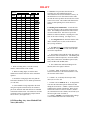
8-8 Time Zones
a. The mean sun revolves around the Earth once
every 24 mean solar hours (one mean solar day) and
each hour the mean sun travels along an arc that is
15° wide. Each of these 15° arcs is referred to as a
time zone. Each of the 24 time zones is designated
by a letter A-Z (J omitted). (See Figure 8-23.)
b. The Prime Meridian is used as a basis of reference
for time zones. Time at a point lying 15° west of the
Prime Meridian is 1 hour earlier than at the Prime
Meridian because the Sun has not yet crossed 15° W
longitude. The opposite is true for a point lying 15°
east of the Prime Meridian, where time is 1 hour later
since the sun has already crossed 15° E longitude.
Therefore, the difference in local time between two
places equals the difference in longitude between the
two places. (See Figures 8-20 and 8-23.)
Celestial Equator
Figure 8-19 Concepts of Sidereal Time
2. Sidereal time for any point is the amount of time
that has elapsed since the vernal equinox last passed
the meridian at that point. Hence, Local Sidereal
Time (LST) is the amount of time that has elapsed
since the vernal equinox last passed the observer's
meridian; Greenwich Sidereal Time (GST) is the
amount of time that has elapsed since the vernal
c. Each 15° meridian east and west of the Prime
Meridian is referred to as a standard meridian. Each
zone extends 7.5° east and west of the standard
meridian. Therefore, the time zone including the
Prime Meridian extends from 7.5° E longitude to 7.5°
W longitude and the time zone with a standard
meridian at 90° W longitude extends from 97.5° W to
82.5° W. Four of these meridians (75°, 90°, 105°,
and 120°) cross the US. (See Figure 9-21.)
DRAFT
Pacific
Time
PST
1 Hour
Mountain
Time
MST
Central
Time
CST
Eastern
Time
EST
1 Hour
120W
120° W
M/15 = TZ
15° W
Figure 9-20
Sun
0°
15° E
Time and Apparent Motion of the
105° W
105W
82° 30' W
Standard Meridian
90° W
7° 30' W
75°
W
75W
Figure 8-22 Political Time Zones in the US
e. To preclude the problem of compiling and
publishing time data for each of the 24 time zones,
data was computed pertaining to one standard time
zone. Standard time zone Z, which uses the
Greenwich Meridian as a Standard Meridian, was
chosen.
d. Standard time zone boundaries are often irregular,
especially over land areas. Time zones generally
follow the 7.5° boundary rule except when those
boundaries are shifted to conform to geographical or
political boundaries. For example, Ft Sill OK lies
closer to the 105° W standard meridian, but for
political boundary purposes, all of Oklahoma is
located in the time zone using the 90° W standard
meridian. Artillery surveyors use the term local
mean time (LMT) in referring to standard time or
local time in a referenced locale. In other words, the
time used by the local inhabitants is local mean time,
unless a non standard time is in use.
97° 30' W
90° W
90W
7° 30' E
Figure 8-21 Time Zone Boundaries
Figure 8-23 Time Zone Letter Designations and Corrections; Local to Greenwich Mean Time
DRAFT
Figure 9-24 World Time Zone Chart (Local to Greenwich )
Greenwich standard time (Zulu time),
also known as Greenwich Mean Time (GMT) or
Universal Time, is defined as the length of time since
the mean sun last crossed the 180th meridian (lower
transit of the Greenwich Meridian) or solar midnight.
This time can be expressed as the reading of the
standard 24 hour clock at the Greenwich observatory
at the moment an observation is made on a celestial
body; hence, it is the same time throughout the world.
Therefore, since the observer's clock is usually set to
standard (local) time, that time (LMT) must be
converted to GMT. (See Figure 8-18.)
8-9 Daylight Savings Time
Daylight savings time is clock time advanced by 1
hour from standard time. Effective 1987, federal law
required that daylight saving time be observed from
the first Sunday in April until the last Sunday in
October; however, individual states may exempt
DRAFT
themselves. During World War II, a double daylight
saving time (2 hour advance) was observed
nationwide and was called wartime.
(GHA). The Greenwich hour angle is the amount of
time that has elapsed since the Sun last crossed the
Greenwich upper meridian (upper transit).
8-10 Greenwich Mean Time (GMT)
2. To determine the Local Hour Angle in mils of
arc, the GHA and the observer’s longitude must be
converted to mils of arc. If the observer is located in
the western hemisphere, the LHA is determined by
subtracting the observer's longitude (mils of arc) from
the GHA in mils. If the observer is located in the
eastern hemisphere, the LHA is determined by adding
the observer's longitude (mils of arc) to the GHA in
mils.
a. Converting LMT to GMT. Local Mean Time
can easily be converted to Greenwich Mean Time by
applying a time zone correction. (See Figure 8-23.)
1. Western Hemisphere. If the observer is
located in the western hemisphere, divide the value of
the standard meridian of the local time zone by 15°.
The result is the time zone correction in hours. Add
this correction to the LMT to determine GMT of the
observation. If this result is greater than 24 hours,
subtract 24 hours and add 1 day to obtain the
Greenwich time and date.
2. Eastern Hemisphere. If the observer is located
in the eastern hemisphere, divide the value of the
standard meridian of the local time zone by 15°. The
result is the time zone correction in hours. Subtract
this correction from the LMT to determine the GMT
of the observation.
b. Converting Greenwich Apparent Time (GAT)
to GMT. When the Marine artillery surveyor makes
observations on the Sun, he actually observes the
apparent sun on the celestial sphere and not the mean
sun on which his clock is based. Consequently, the
surveyor must convert his Greenwich Apparent Time
(GAT) to GMT. This correction is contained within
the Arty Astro program and need not be determined
manually. The correction is provided in Table 2 of
the Army Ephemeris using the observation date as an
entry argument. The resultant equation of time (see
paragraph 8-6.d) for zero hours GMT (0h) and the
daily change are used to determine a correction for
the date and proportionate part of the day to be
applied to the GMT of the observation.
8-11 Determining the Local Hour Angle
(LHA) and Angle t
a. Determining Local Hour Angle (LHA).
1. When the position of the apparent sun at the
time of observation has been determined and related
to the Greenwich meridian, the time is referred to as
Greenwich apparent time (GAT). By simply adding
12 hours to, or subtracting it from, the GAT (the
result cannot exceed 24 hours), the surveyor
determines the value of the Greenwich hour angle
b. Determining Angle t. Angle t is the angle in the
PZS triangle at the polar vertex. It is determined as
discussed below:
1. If the local hour angle is greater than 3200 mils,
angle t equals 6400 mils minus the LHA.
2. If the local hour angle is less than 3200 mils,
angle t equals the LHA.
Section II
ASTRONOMIC METH
8-12 Methods of Determining Azimuth
a. General. The primary astronomic method Marine
artillery surveyors will use is the Arty Astro Method.
Arty Astro is based on the Hour Angle Method and
can be used with the Sun or stars. With the advent of
the PLGR, and SINCGARS, accurate time is now
readily available to surveyors, making Arty Astro the
preferred method. At the battery level the Hasty Astro
Method of observation will be used, and is discussed
in Chapter 11.
b. Arty Astro (Hour Angle) Method. In the Arty
Astro Method, using two sides and the included angle
DRAFT
Pol
ar
3. Accurate time of the observation to determine
the local hour angle.
b. Position of the Sun. For the Sun to be suitable
for use with the Arty Astro Method, it must not be
within one hour of the observer's meridian. It must be
between 175 mils and 1300 mils (preferably between
175 and 800) above the observer's meridian. An
experienced instrument operator may observe the Sun
Latitu
de
Azimuth
Angle
Celestial Equator
Figure 8-25
a. General. The Arty Astro Method may be used to
determine azimuths from Sun observations. The Arty
Astro Method does not require the measurement of
a vertical angle or temperature and, the computations
do not include a refraction or parallax correction.
This method was once referred to as the Hour Angle
Method because the solution of the PZS triangle is
dependent on solving the local hour angle.
Z
n
Declinatio
2. Declination of the observed body to determine
the side polar distance.
de
titu
S
1. Latitude of the observer to determine the side
Colatitude.
8-13 Arty Astro (Hour Angle) Method
Sun
Local Hour Angle
Dis
tan
ce
P
la
Co
solves the azimuth angle of the PZS triangle. The
sides are the polar distance and the Colatitude; the
angle is the local hour angle (angle t). In addition to
the horizontal angle from an azimuth mark to the
observed body, three elements must be determined
(See Figure 8-25.):
Solving the Arty Astro Method
above 800 mils with an elbow telescope or with the
card method.
c. Time. In the Arty Astro Method (Sun), time is
critical to the accurate determination of the local hour
angle. For this reason, time must be accurate to 1
second. Accurate time is available through radio time
signals and GPS receivers (i.e. PLGR, MSGR,
SINCGARS).
d. Solving the PZS Triangle. The formula for
solving the PZS triangle has been arranged in a
manner as to require only the determination of the
local hour angle. The two sides are stated in the
formula in terms of declination of the sun and
latitude, thus eliminating the need for the
computations of polar distance and Colatitude.
1. The computation of the polar distance is not
necessary since the formula uses the Sun's
declination.
2. The computation of the Colatitude is not
necessary since the formula uses the observer's
latitude.
3. Determination of Local Hour Angle (LHA).
For the hour angle solution, the element of the PZS
triangle that is necessary is the local hour angle. This
angle is determined by using the time of the
observation. In general terms, the local hour angle is
determined by converting the local mean time (watch
time) to Greenwich mean time, to Greenwich
apparent time, to Greenwich hour angle, and finally to
the local hour angle. More specifically, this
conversion can be performed as outlined below:
DRAFT
Local mean time
+time zone correction
=Greenwich mean time
±equation of time for 0h
±daily change for portion of day
=Greenwich apparent time
±12 hours
=Greenwich hour angle
±longitude
=local hour angle
Greenwich Mean Time (GMT). The watch time of
the observation is referred to as local mean time.
This watch time is standard time for the area of
operation. By applying a time zone correction the
Greenwich mean time (Zulu Time) is obtained. This
step can be skipped if the watch is set to Zulu time.
(See Figure 8-26.)
Greenwich Apparent Time (GAT). Greenwich
apparent time (GAT) is the time that has elapsed
since the last passage of the apparent sun over the
lower transit of the Greenwich meridian. GAT is
obtained by applying the equation of time and the
proportionate part of the daily change in the equation
of time to the GMT.
Greenwich Hour Angle (GHA). The Greenwich
hour angle (GHA) is the amount of time that has
elapsed since the sun last crossed the Greenwich
meridian; therefore, Greenwich apparent time is
always ± 12 hours from the Greenwich hour angle.
To determine the Greenwich hour angle, simply add
or subtract 12 hours to or from the Greenwich
apparent time, remembering that the result must be
between 0 and 24 hours.
Local Hour Angle (LHA). The local hour angle
(LHA) of a celestial body is the time that has elapsed
since that celestial body last crossed the observer's
meridian. The formula used to determine the local
hour angle depends on the hemisphere (east or west)
of the observer. In the western hemisphere, both the
longitude and the Greenwich hour angle are measured
west from the Greenwich meridian; therefore, the
LHA equals the GHA minus Longitude (LHA = GHA
- Long.). In the eastern hemisphere, longitude is
measured to the east, the GHA is still measured to the
west; therefore, the LHA in the eastern hemisphere is
equal to the sum of the GHA and the longitude minus
360° (LHA = (GHA + Long.) - 360°).
4. Several formulas can be derived for the solution
of the spherical triangle when two sides and an
included angle are known. The following formula
was selected for use in artillery survey because of its
simplicity:
tan ½ (A + q) =
tan ½ (A – q) =
Where:
cos ½ (Lat – Dec) cot ½ t
sin ½ (Lat + Dec)
sin ½ (Lat – Dec) cot ½ t
cos ½ (Lat + Dec)
A is the astronomic azimuth (true) of the
Sun measured east or west of the
meridian.
q is the parallactic angle (cancels out in
computations.
Lat is the latitude of the station.
Dec is the apparent declination of the sun
t is the local hour angle (less than 12h) of
the sun.
e. Computations. Survey computer systems (i.e.
HCS) contain the Arty Astro program that easily
computes an azimuth from the astronomic
observations performed. The required ephemeris data
and time calculations are completed within the
program and do not require any "manual"
computation.
8-14 Arty Astro (Hour Angle) Method
Star
a. General. The Arty Astro Method may be used to
determine azimuths from observations on any of the
73 survey stars. Observations of the stars are
generally considered to be preferred over those or the
Sun due to more accurate sighting. The preferred star
for this method in the Northern Hemisphere is Polaris
as it displays the least apparent motion being a
circumpolar star. (In the Southern hemisphere the
preferred star is Alpha Acrux.) The Arty Astro
Method does not require the measurements of a
vertical angle or a temperature and the computations
do not include a refraction or parallax correction.
This method was once referred to as the Hour Angle
Method because the solution of the PZS triangle is
dependent on solving the local hour angle.
b. Position of the Stars. Polaris may be observed
any time it is visible, but best results are obtained
when it is 175 mils or higher above the observer's
horizon. East west stars can be selected by using the
star finder and star rate template. The 175-mil
restriction minimizes the effects of refraction.
c. Time. In the Arty Astro Method (star), time is
critical to the accurate determination of the local hour
angle. For this reason, time must be accurate to 10
DRAFT
seconds for observations on Polaris and 1 second for
observations on east-west stars. Accurate time is
available through radio time signals and GPS
receivers (i.e. PLGR, MSGR, SINCGARS).
d. Solving the PZS Triangle. The formula for
solving the PZS triangle with star observations is the
same as for the Sun. The only difference in the
computations is that sidereal time is used to
determine the local hour angle. In general terms, the
local hour angle is determined by converting the local
mean time (watch time) to Greenwich mean time, to
Greenwich sidereal time, to Greenwich hour angle,
and finally to the local hour angle; as outlined below:
Local mean time
+time zone correction
=Greenwich mean time
±sidereal time for 0h GMT
±correction for GMT
=Greenwich sidereal time
-right ascension of the star
=Greenwich hour angle
±longitude
=local hour angle
Greenwich Mean Time (GMT). The watch time
of the observation is referred to as local mean time.
This watch time is standard time for the area of
operation. By applying a time zone correction (see
Figure 9-20) the Greenwich mean time (Zulu Time) is
obtained. This step can be skipped if the watch is set
to Zulu time.
Greenwich Sidereal Time (GST). Greenwich
sidereal time is the time elapsed since the vernal
equinox last crossed the Greenwich meridian. GST is
obtained by applying the sidereal time at 0h GMT
(Army Ephemeris, Table 2) and the correction for
GMT (Army Ephemeris, Table 4) to the Greenwich
mean time.
Greenwich Hour Angle (GHA). The Greenwich
hour angle is the time elapsed since the celestial body
last crossed the Greenwich meridian. The GHA is
obtained by subtracting the right ascension from the
Greenwich sidereal time.
Local Hour Angle (LHA). The local hour angle
(LHA) of a celestial body is the time that has elapsed
since that celestial body last crossed the observer's
meridian. The formula used to determine the local
hour angle depends on the hemisphere (east or west)
of the observer. In the western hemisphere, both the
longitude and the Greenwich hour angle are measured
west from the Greenwich meridian; therefore, the
LHA equals the GHA minus Longitude (LHA = GHA
- Long.). In the eastern hemisphere, longitude is
measured to the east, the GHA is still measured to the
west; therefore, the LHA in the eastern hemisphere is
equal to the sum of the GHA and the longitude minus
360° (LHA = (GHA + Long.) - 360°).
e. Computations. Survey computer systems (i.e.
HCS) contain the Arty Astro program that easily
computes an azimuth from the astronomic
observations performed. The required ephemeris data
and time calculations are completed within the
program and do not require any "manual"
computation.
8-15 Azimuth Specifications
a. The arty astro method can be used to determine
either fourth or fifth order azimuth. For Marine
artillery surveyors, a T2-E theodolite is used in each
echelon of survey.
b. At least three sets of observations must be made
on the celestial body. For fifth order, mean the three
sets and reject any set that varies from the mean by
more than 0.3 mils. For fourth order, mean the three
sets and reject any set that varies from the mean by
more than 0.15 mils. At least two sets must remain to
determine the final azimuth (both fourth and fifth
order).
c. The considered accuracy for a fifth order
astronomic azimuth is ±0.3 mils and ±0.15 mils for a
fourth order azimuth.
8-16 Selection of Methods of Observation
a. General. The Marine artillery surveyor must
consider several factors when selecting a method of
observation. These considerations include the
following:
1. Day or night, north or south latitude.
2. Accuracy of the watch time.
3. Positions of celestial bodies at specific times.
4. Degree of accuracy required.
5. Observer's position accuracy. This
consideration is more important for the computation
of UTM grid convergence (true azimuth to grid
DRAFT
azimuth) than for the actual observation
computations.
6. The experience of the instrument operator
b. Procedures. Specific procedures to observe
celestial bodies are outlined in Chapter 7 Section I.
Section III
STAR SELECTION AND IDENTIFICATION
8-17 General
a. There are important advantages to using stars
rather than the sun as a source for astronomic
azimuths. Since stars appear as pinpoints of light in
the telescope they are easier to track. At least one of
the 73 survey stars can be found in a position that will
allow for astronomic observation, regardless of the
observer's location or the time of night.
b. Polaris should always be used when it is visible.
Polaris is the most desirable star to observe because it
is usually easy to locate and because its slow apparent
motion makes it easy to track. Because of weather
conditions, ambient light, line of sight barriers, or the
observer's latitude, Polaris may not always be
available. In this case, an east-west star must be used.
East-west stars must be selected based on their star
rate and their position relative to the observer. A Star
Finder and Identifier will aid in selecting and
identifying usable east-west stars.
visible throughout the night in most of the northern
hemisphere. When the Polaris local hour angle is 0
or 12 hours, the star is said to be in its upper or lower
culmination, respectively. When the Polaris local
hour angle is 6 or 18 hours, it is said to be in its
western or eastern elongation. The small orbit of
Polaris results in a very slow apparent motion, so the
star may be observed at any point in its orbit. The
least chance of error will occur when Polaris is in
elongation. (See Figure 8-27.)
Upper
Culmination
0 hrs
Western
Elongation
Celestial
North Pole
6 hrs
18 hrs
Eastern
Elongation
8-18 Polaris
a. Orbit of Polaris. Polaris appears to move in a
small, elliptical, counterclockwise orbit about the
celestial North Pole. The size of this apparent orbit
varies slightly with the observer's latitude; at 35° N
latitude, its minor diameter is about 45 mils. Because
Polaris stays so close to the north celestial pole, it is
12 hrs
Lower
Culmination
Figure 9-27
Orbit of Polaris
b. Identification of Polaris.
1. Polaris is the brightest star in the constellation
Ursa Minor (Little Dipper), which is near the
constellations Ursa Major (Big Dipper) and
Cassiopeia (Lazy W). Polaris is the anchor (end) star
of the handle of the Little Dipper.
DRAFT
2. Polaris can be identified by its relative position
to Ursa Major. The two stars forming the side of the
bowl farthest from the handle of the Big Dipper are
called the "pointer stars". An imaginary line
extended through the pointer stars towards Cassiopeia
nearly passes through the celestial North Pole.
Polaris is approximately five times the distance
between the pointer stars along the imaginary line
from the Big Dipper. (See Figure 8-28.)
3. Polaris can also be identified by its relative
position to Cassiopeia. Since Cassiopeia is on the
same side of the celestial North Pole as Polaris, its
position relative to the pole is approximately the same
as Polaris'. Therefore, Cassiopeia can be used to
determine whether Polaris is in elongation or
culmination. A line drawn from the star Ruchbah,
bisecting the shallow side of Cassiopeia, will pass
closely by Polaris. (See Figure 8-28.)
4. The vertical angle to the celestial North Pole is
equal to the observer's latitude; therefore, the vertical
Figure 8-28 Identification of Polaris
angle to Polaris is approximately equal to observer's
latitude.
a. Because the celestial sphere, and therefore the
celestial North Pole, is an infinite distance from the
Earth, the line to the celestial North Pole from the
observer can be considered the same as the line of the
rotational axis of the Earth (and celestial sphere).
Angle A represents the observer's latitude; angle B
the vertical angle to the celestial North Pole. The
laws of geometry prove that since the observer's
zenith is perpendicular to the observer's horizon, and
since the line to the celestial north pole is
perpendicular to the plane of the celestial equator,
angles A and B must be equal. (See Figure 8-29.)
b. When the observer's latitude in mils is subtracted
from 1600 mils, the result is the vertical reading to
the celestial north pole (angle C in Figure 8-29).
When that vertical reading is set on the vertical scale
of the theodolite in the direct mode, Polaris will
appear in the field of view. If the star is at
elongation, its vertical angle is equal to the observer's
latitude. When Polaris is moving from eastern to
western elongation, its vertical angle is greater than
the observer's latitude; when Polaris is moving from
western to eastern elongation, its vertical angle is less
than the observer's latitude.
DRAFT
Resulting
Azimuth
Error
Figure 8-29 Relationship Between the
Observer's Latitude and the Vertical Angle to the
Celestial North Pole.
5. When a pointing is made on Polaris, the observer
will see two other stars nearby which are not visible
to the naked eye. However, when the reticle pattern
in the telescope is illuminated, Polaris will be the
only visible star.
8-19 Star Rate
If Polaris is not visible, an east-west star may be
observed. East-west stars should be selected
according to their star rate.
Resulting
Azimuth Error
Apparent
Path of Star
Vertical
Measurement
Error
Apparent
Path of Star
Vertical
Measurement
Error
Figure 8-31
Low Star Rate
b. The star rate of a celestial body is largely
dependent on the observer's latitude. Because
vertical angles are not measured in the Arty Astro
method, any east-west star can be observed.
However, bodies with a low star rate also have a
smaller apparent horizontal motion; therefore, those
stars with a low star rate are preferred because they
are easier to track. Even though Polaris has a high
star rate in its culmination, its apparent motion is slow
so it can be observed any time it is visible with the
Arty Astro method. Stars below 175 mils in vertical
angle, even those with a low star rate, must not be
observed because of the increased effects of
refraction.
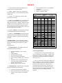
c. Appendix E includes star rate charts that can be
used to select stars based on their star rate. The chart
used should be the one closest to the latitude of the
user and will be the same latitude as the template of
the star finder and identifier. The areas marked on
the charts are as follows:
Figure 9-30
High Star Rate
a. The apparent motion of a celestial body has two
measurable components: a horizontal motion (change
in azimuth), and a vertical motion (change in
altitude.) The star rate of the body is equal to the
ratio between the two components. In other words,
when a 1-mil error in the vertical angle causes an
azimuth error of 3 mils, the star rate is 3. When
observing a star that moves at a small angle relative
to the horizon, a small error in vertical angle will
result in a large error in azimuth. When observing a
star that moves at a large angle relative to the
horizon, an error in vertical angle will result in a
smaller error in azimuth. (See figures 8-30 and 8-31.)
1. Block A: Star rates from 0 - 0.5. The dotted
line represents a rate of zero. These are the most
desirable stars.
2. Block B: Star rates from 0.5 - 1.0. These are
the second most desirable.
3. Block C: Star rates from 1.0 - 3.0.
4. Block D: Star rates over 3.0. These stars can
be used for Arty Astro in extreme cases.
5. Star rates above 60° altitude are not listed and
stars located in that area should not be used.
DRAFT
8-20 Star Finder and Identifier
a. General. The star finder and identifier is a device
used to determine the approximate (±2°) azimuth and
altitude of selected stars.
b. Base and Templates. The star finder and
identifier consist of a base, ten templates, and a case.
1. Base. The base is a two-sided star chart. One
side displays stars of the northern hemisphere, the
other side the southern hemisphere. The center of
each side represents the celestial pole, north or south
dependent on the side of the base. The edge of the
base is a circle graduated in half degrees and
numbered counter- clockwise every five degrees.
These graduations represent the local hour angle of
the vernal equinox or the local sidereal time (LST).
base. Local sidereal time can be determined in
several ways, each requiring the same information:
§
§
§
Observation Date
Observation Time
Longitude of the Observer
a. DA Form 6-21. This manual computation form
allows the user to determine the LST by means of
simple mathematical computations and the extraction
of several data from charts displayed on the back of
the form.
b. Survey Computer Systems. Survey computer
systems (HCS) will allow the user to compute the
LST by means of input of the above data. For
instructions on the operations of these systems,
consult the user's manual for that equipment.
2. Templates. The star finder and identifier
include ten templates. One which is used to plot the
Sun and planets (not used by artillery surveyors); and
nine to identify stars and determine their position
once the template is properly oriented. The nine
templates are clear plastic that allow the user to view
the stars displayed on the base. Each template is
constructed for a specific latitude starting at 5° and
increase in 10 degree increments to 85°. The
templates are two sided, one side for north latitudes
and the other side for south latitudes. The user
selects a template that corresponds closest to his
latitude. On each template is a series of concentric
ellipses. Around the outer edge of these ellipses are
two sets of numbers from 0° to 360°. The inner set of
numbers, numbered clockwise, start at the top of the
template and are readable for north latitudes. The
outer set of numbers, also numbered clockwise, start
at the bottom of the template and are readable for
south latitudes. The 0° - 180° line represents the
observer's meridian; the other numbers represent the
azimuth from the celestial pole, north or south, to the
line identified by those numbers. The templates
display the observer's horizon as the outer ellipse.
The center of the ellipses is the observer's zenith.
The series of concentric ellipses represent the altitude
in degrees above the horizon of the celestial body.
c. Haught Method. This is an easy field-expedient
method of determining LST accurate to 1° and can be
used for any time and location. The final result from
these computations is the LST for 1900 hours on the
date of observation. The time-arc relationship is then
used to determine the LST for the actual observation
time. The Haught Method is performed as follows:
8-21 Orienting the Star Finder and
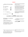
Identifier.
**The result is the LST for 1900 hours.
The star finder and identifier is oriented by placing
the arrow at the 0° - 180° line of the template over the
local sidereal time (LST) on the outer edge of the
1. Count the number of months this year prior to
the current month. Multiply that number by 30.
2. Add the calendar day of the current month.
(If the Julian Date of the observation is known, use
the Julian Date instead of steps 1 and 2.)
3. Add a constant of 24.
4. Determine the difference between the observer's
longitude and the longitude of the time zone central
meridian (CM). Add the difference if the observer is
east longitude, subtract if the difference is west
longitude.
5. If using daylight savings time (DST), subtract
15. In the US, DST is from the first Sunday in April
to the last Sunday in October.
6. Determine the difference between 1900 and the
time of observation. Add 15° for each hour after
1900 and 1° for each 4 minutes after the whole hour.
If the observation time is prior to 1900, subtract the
correction.
DRAFT
7. Sample. An astronomic observation will be
made at 2230 on July 23. The observer's longitude is
98°.
Step 1: # of full months x 30
Step 2: Observation Date
Step 3: Add 24
Step 4: Offset from CM
Step 5: Correction for DST
LST for 1900 hours
selection of a star by its star rate can be performed by
plotting the position of selected stars on the star rate
charts listed in Appendix E.
b. Determine the Position of a Star. Once the stars
have been selected, the observer can either plot the
azimuth and altitude to the celestial body from the
template of the star finder and identifier or he can
enter the star number (or name dependent on the
system) of the celestial body into a survey computer
system. Either method is adequate for locating the
star in the telescope of a T-2E Theodolite.
180
23
+24
227
-8
219
-15
204
c. Identification of stars other than Polaris is aided
Step 6: Observation time difference
is 3h 30m.
3 x 15 = 45
30 / 4 = 7.5
LST for 2230 on 23 July is
by the Star Cards and the World Star Chart included
in Appendix E. The star cards display the stars in
their constellations, and the star list provides the star
number and magnitude.
+52.5
256.5
Section IV
RECORDING ASTRONOMIC OBSERVATIONS
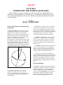
8-23 Recording Arty Astro Method Field
Notes (5th order).
a. General. The procedures listed below for
recording Arty Astro Method astronomic
observations will be used for 5th order accuracy.
1. The designation block should be filled in with
ARTY ASTRO (Sun) or (Star) as the method of
survey being conducted.
2. The date block must be filled in with the date
the fieldwork was performed. This will be the date
used in the computations.
b. Heading and Column Titles. As with all field
notes, the first page of the recorder's notebook is the
index. The heading and column titles will be filled
out as described below. (See Figure 8-32.)
3. The heading of the right side of the page will be
8-22
Selecting
a Starand
forColumn
Observation
Figure
8-32 Heading
Titles (5th Order Arty filled
Astro)
out the same as with traverse. This heading will
a. General. A star should be selected for its star
rate, or the rate of its apparent motion. There are
however, other considerations depending on the
method of astronomic observation used. Once the
star finder and identifier is properly oriented,
include the weather description, T-2E serial number,
Party Chief (COP) name, Instrument Operator (IO)
name, and Recorder (RCDR) name.
DRAFT
§
4. The column titles under the heading will be
labeled (from left to right) as follows:
Weather phenomena not covered in header
information.
RCDR, IO, COP initial blocks
Approx. azimuth to AzMk
§
§
a. Column 1: STA; to identify the occupied, rear,
and forward stations. The forward station star name
will be listed.
WEATHER
b. Column 2: T; to identify the telescope mode,
direct (D) or reverse (R).
INST#
CLEAR, WARM
CHIEF OF PARTY
INSTR OPR
RCDR
LCPL SMUCKATELLY
LCPL GUNGHO
2
LCPL GRUNT
T2E - # 123456
REMARKS
c. Column 3 and 4: TIME (h m s); to designate the
exact time the instrument operator announced TIP
during the observations. "TIME" is split between the
columns in the top half of the blocks. Hours (h) are
listed in the lower left corner of column 3, minutes
(m) centered between the columns, and seconds (s) in
the lower right corner of column 4.
OS is a wooden hub, 14 meters south of the centerline of the dirt trail
south of GP 2. The EOL is 102 meters west of the OS.
KNOWN DATA IS FROM PADS OPERATIONS DTD 29 JAN 93:
EASTING:
WGS-84
GRID ZONE: 14
d. Column 5: HORZ; to record horizontal readings
to the azimuth mark and to the celestial body.
e. Columns 7-12: REMARKS; this side of the page
will be used to record information pertinent to these
observations. Entries are discussed in the following
paragraph.
c. Remarks Entries. The remarks page includes
both required entries and some optional information
that may be needed by the computer or for future
reference.
(See Figure 8-33.)
554010.6
NORTHING: 3834962.1
All observations made to the center of the sun.
!!!!! ALL TIMES RECORDED ARE ZULU TIMES !!!!!!
GP 2
Dirt Trail
N
EOL
OS
RCDR
I.O.
C.O.P.
1. Required Entries. The remarks section will
include the following information:
§
§
§
§
§
§
§
Easting and Northing of the Occupied
Station.
UTM Grid Zone.
Horizontal Datum/Ellipsoid.
Source of the position information.
Center, leading, or trailing edge if using the
sun.
Time Zone Letter (If using local time, an
entry must be made indicating Daylight
Savings or Standard Times).
Sketch; as close to scale as possible.
2. Optional Entries. Optional entries can include,
but are not restricted to, the following:
§
§
§
Location of occupied and rear stations.
Route to these locations from a known point.
Changes to data in trig list concerning the
stations.
Figure 8-33 Remarks For Arty Astro
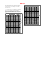
d. Recording Field Data.
1. Field data will be recorded in the columns and
rows corresponding to the pointing. In other words,
the initial circle setting is recorded in the horizontal
angle column, in the rear station/direct reading row.
(See Figure 8-34.)
2. The "T" (telescope) column will be filled out as
shown in Figure 8-36. The rear station (AzMk) name
will be recorded in the direct (D) mode row directly
below the "STA" column title. Skip one line to
record the occupied station name. Skip one line to
record the forward station (celestial body) name to
the left of the first direct pointing on the body. If the
celestial body is a star, the star name must be
recorded.
DRAFT
DESIGNATION
STATION
OCS WT
ARTILLERY ASTRO (SUN) DATE 4 DEC
T I ME
T
h
m
s
90
HORZ
D
0000.191
R
3200.124
4282.014
ABLE 2
SUN
19
D
20
50
48 5970.202
D
20
51
49 5974.008
D
20
52
39 5977.221
a. General. The procedures listed below for
recording Arty Astro Method astronomic
observations will be used for 4th order accuracy. In
this method two sets of observations will be made;
one with the telescope in the direct mode, the second
in the reverse mode. This method will minimize the
effects of small pointing errors on the observed
stations.
b. Heading and Column Titles. As with all field
notes, the first page of the recorder's notebook is the
index. The heading and column titles will be filled
out as described below. Note that except for the
addition of column 6, MEAN, everything else is the
same as 5th order recording. (See Figure 8-35.)
1. The designation block should be filled in with
ARTY ASTRO (Sun) or (Star) as the method of
survey being conducted.
2. The date block must be filled in with the date
the fieldwork was performed. This will be the date
used in the computations.
3. The heading of the right side of the page will be
filled out the same as with traverse. This heading will
include the weather description, T-2E serial number,
Party Chief (COP) name, Instrument Operator (IO)
name, and Recorder (RCDR) name.
Figure 8-34 Field Data (5th Order) For Arty Astro
3. When recording times, record the seconds,
minutes, and then hours (24 hr format).
4. When recording angles, record the entire
number then read the value back to the instrument
operator.
5. Record the closing angle and verify that the
horizontal collimation error is within specifications
(±0.150 mils).
6. If the azimuth is being computed in the field
using the computer's internal clock, the solution is
part of the fieldwork and must therefore be included
in the field recorder's book. The solution is recorded
in column 6 in the row listing the occupied station
and is circled. (See Figure 8-34.)
8-24 Recording Arty Astro Method Field
Notes (4th order).
4. The column titles under the heading will be
labeled (from left to right) as follows:
a. Column 1: STA; to identify the occupied, rear,
and forward stations. If the forward station is a star,
the star name will be listed.
b. Column 2: T; to identify the telescope mode,
direct (D) or reverse (R).
c. Column 3 and 4: TIME (h m s); to designate the
exact time the instrument operator announced TIP
during the observations. "TIME" is split between the
columns in the top half of the blocks. Hours (h) are
listed in the lower left corner of column 3, minutes
(m) centered between the columns, and seconds (s) in
the lower right corner of column 4.
d. Column 5: HORZ; to record horizontal readings
to the azimuth mark and to the celestial body.
DRAFT
Figure 8-35 Heading and Column Titles (4th Order Arty Astro)
d. Recording Field Data.
e. Column 6: MEAN; to record the solutions for the
direct and reverse sets; and to record the mean
1. The first set in this method is recorded the same
solution of the sets.
as the procedures listed for 5th order except that the
solution is not circled, it is placed in parenthesis.
f. Columns 7-12: REMARKS; this side of the page
(See Figure 8-36.)
will be used to record information pertinent to these
observations. Entries are discussed in the following
2. The "T" (telescope) column will be filled out as
paragraph.
shown in Figure 8-36. There will be three spaces
between the last direct reading in the first set and the
c. Remarks Entries. The remarks page includes
initial circle setting ("R" reverse reading) in the
both required entries and some optional information
second set.
that may be needed by the computer or for future
reference. (See Figure 8-33.)
1. Required Entries. The remarks section will
include the following information:
§
§
§
§
§
§
§
Easting and Northing of the Occupied
Station.
UTM Grid Zone.
Horizontal Datum/Ellipsoid.
Source of the position information.
Center, leading, trailing edge if using the
Sun.
Time Zone Letter (If using local time, an
entry must be made indicating Daylight
Savings or Standard Times).
Sketch; as close to scale as possible.
2. Optional Entries. Optional entries can
include, but are not restricted to, the following:
§
§
§
§
§
§
Location of occupied and rear stations.
Route to these locations from a known point.
Changes to data in trig list concerning the
stations.
Weather phenomena not covered in header
information.
RCDR, IO, COP initial blocks
Approx. azimuth to AzMk
3. The second set is recorded as follows:
a. The rear station (AzMk) name will be recorded in
the reverse (R) mode row in the second set. Skip one
line to record the occupied station name. Skip one
line to record the forward station (celestial body)
name to the left of the first reverse pointing on the
body. If the celestial body is a star, the star name
must be recorded.
b. When the fieldwork was completed for the first
set, the instrument operator had a pointing on the rear
station in the reverse mode. This was the closing
angle for the first set. The recorder will enter that
closing angle as the initial circle setting for the
second set. The instrument operator needs only to
observe the celestial body in the reverse mode and
close the angle in the direct mode to complete the
second set. (See Figure 9-37.)
b. When recording times, record the seconds,
minutes, and then hours (24 hr format).
c. When recording angles, record the entire number
then read the value back to the instrument operator.
d. Record the closing angle and verify that the
horizontal collimation error is within specifications
(±0.150 mils).
e. If the azimuth is being computed in the field using
the computer's internal clock, the solution is part of
the fieldwork and must therefore be included in the
field recorder's book. The solution is recorded in
column 6 (MEAN) in the row listing the occupied
station and is placed in parenthesis. The azimuth
DRAFT
determined from the direct readings must equal the
azimuth from the reverse readings, ± 0.150 mils.
(See Figure 8-37.)
DESIGNATION
STATION
OCS WT
4. After the second set is computed, the solutions for
the two sets are meaned. The mean azimuth is
recorded in column 6 (MEAN) in the center row of
the three spaces between the two sets. (See Figure 837.)
DESIGNATION
STATION
OCS WT
ARTILLERY ASTRO (SUN)
DATE
TIME
T
h
m
s
4 DEC
HORZ
D
0000.191
R
3200.124
19
OCS WT
TIME
T
h
m
s
4 DEC
HORZ
D
0000.191
R
3200.124
SUN
D
20
50
48 5970.202
D
20
51
49 5974.008
D
20
52
39 5977.221
20
50
48 5970.202
D
20
51
49 5974.008
D
20
52
39 5977.221
R
3200.124
ABLE 2
R
R
R
Figure 8-36 Field Data (4th Order) For Arty Astro
90
MEAN
4282.002
OCS WT
R
3200.124
D
0000.196
(4281.990)
ABLE 2
D
19
(4282.014)
MEAN
D
SUN
DATE
ABLE 2
90
ABLE 2
SUN
ARTILLERY ASTRO (SUN)
SUN
R
20
55
R
20
56
16 2790.707
R
20
57
01 2793.403
32 2787.911
Figure 8-37 Field Data (4th Order) For Arty Astro