1
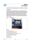
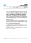
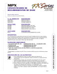
UM0522
User manual
100 W 3-phase inverter for BLDC sensorless motor
evaluation board
Introduction
The 100 W 3-phase inverter for the BLDC sensorless motor evalaluation board (for brevity
also referred with its order code STEVAL-IHM017V1) is a complete development platform
for BLDC sensorless motor application with nominal power up to 100 W. It is based on a
cost-effective, flexible and open design, including a three-phase inverter bridge based on
the STD5NK52ZD-1 Power MOSFET in IPAK package and an ST7MC 8-bit microcontroller
with 16 Kbyte internal Flash memory.
The system has been designed to drive a three-phase brushless motor with permanent
magnet rotor exploiting trapezoidal sensorless control.
The STEVAL-IHM017V1 features complete hardware for developing motor control
applications based on ST7MC peripherals including motor control peripheral (MTC). The
STEVAL-IHM017V1 uses an in-circuit communication (ICC) standard interface to connect to
the host PC via In-circuit debuggers/programmers such as the inDART-STX board from
Softec. The board is designed to support 230 Vac of bus voltage up to 100 W of input power.
It also includes a power supply stage with VIPer12A-E as the buck converter to generate
voltage reference for the driver and the microcontroller.
Figure 1.
April 2008
STEVAL-IHM017V1 evaluation board
Rev 1
1/39
www.st.com
Contents
UM0522
Contents
1
Overview . . . . . . . . . . . . . . . . . . . . . . . . . . . . . . . . . . . . . . . . . . . . . . . . . . 6
1.1
Features . . . . . . . . . . . . . . . . . . . . . . . . . . . . . . . . . . . . . . . . . . . . . . . . . . . 6
1.2
Applications . . . . . . . . . . . . . . . . . . . . . . . . . . . . . . . . . . . . . . . . . . . . . . . . 6
2
System architecture . . . . . . . . . . . . . . . . . . . . . . . . . . . . . . . . . . . . . . . . . 7
3
Safety and operating instructions . . . . . . . . . . . . . . . . . . . . . . . . . . . . . . 8
4
3.1
General . . . . . . . . . . . . . . . . . . . . . . . . . . . . . . . . . . . . . . . . . . . . . . . . . . . . 8
3.2
Evaluation board intended use . . . . . . . . . . . . . . . . . . . . . . . . . . . . . . . . . . 8
3.3
Evaluation board installation . . . . . . . . . . . . . . . . . . . . . . . . . . . . . . . . . . . 8
3.4
Electronic connections . . . . . . . . . . . . . . . . . . . . . . . . . . . . . . . . . . . . . . . . 8
3.5
Evaluation board operation . . . . . . . . . . . . . . . . . . . . . . . . . . . . . . . . . . . . 9
ST7FMC2S4T6 microcontroller functions . . . . . . . . . . . . . . . . . . . . . . . 10
4.1
Main features . . . . . . . . . . . . . . . . . . . . . . . . . . . . . . . . . . . . . . . . . . . . . . 10
5
STD5NK52ZD-1 characteristics . . . . . . . . . . . . . . . . . . . . . . . . . . . . . . . 12
6
Board electrical characteristics . . . . . . . . . . . . . . . . . . . . . . . . . . . . . . . 13
7
Board architecture . . . . . . . . . . . . . . . . . . . . . . . . . . . . . . . . . . . . . . . . . . 14
8
7.1
Power supply . . . . . . . . . . . . . . . . . . . . . . . . . . . . . . . . . . . . . . . . . . . . . . 14
7.2
Power stage . . . . . . . . . . . . . . . . . . . . . . . . . . . . . . . . . . . . . . . . . . . . . . . 15
7.3
ICC connector . . . . . . . . . . . . . . . . . . . . . . . . . . . . . . . . . . . . . . . . . . . . . 16
7.4
Board schematic . . . . . . . . . . . . . . . . . . . . . . . . . . . . . . . . . . . . . . . . . . . . 17
Motor control operations . . . . . . . . . . . . . . . . . . . . . . . . . . . . . . . . . . . . 19
8.1
Environmental considerations . . . . . . . . . . . . . . . . . . . . . . . . . . . . . . . . . 19
8.2
Hardware requirements . . . . . . . . . . . . . . . . . . . . . . . . . . . . . . . . . . . . . . 19
8.3
Software requirements . . . . . . . . . . . . . . . . . . . . . . . . . . . . . . . . . . . . . . . 20
8.3.1
Installing the software . . . . . . . . . . . . . . . . . . . . . . . . . . . . . . . . . . . . . . 20
STEVAL-IHM017V1 - GUI installation . . . . . . . . . . . . . . . . . . . . . . . . . . . . . . . . .20
3rd party software installation . . . . . . . . . . . . . . . . . . . . . . . . . . . . . . . . . . . . . . . .20
Installation note . . . . . . . . . . . . . . . . . . . . . . . . . . . . . . . . . . . . . . . . . . . . . . . . . .20
2/39
UM0522
Contents
8.4
Board setup . . . . . . . . . . . . . . . . . . . . . . . . . . . . . . . . . . . . . . . . . . . . . . . 21
8.5
Firmware description . . . . . . . . . . . . . . . . . . . . . . . . . . . . . . . . . . . . . . . . 21
8.6
Configuring the firmware using GUI . . . . . . . . . . . . . . . . . . . . . . . . . . . . . 21
8.7
Motor type selection . . . . . . . . . . . . . . . . . . . . . . . . . . . . . . . . . . . . . . . . . 22
8.8
"3-phase BLAC/DC (trapezoidal)" settings . . . . . . . . . . . . . . . . . . . . . . . . 22
8.9
“3-phase BLAC/DC (trapezoidal)" advanced settings . . . . . . . . . . . . . . . . 24
8.10
Changing the maximum current allowed by GUI . . . . . . . . . . . . . . . . . . . 26
8.11
Compiling the firmware . . . . . . . . . . . . . . . . . . . . . . . . . . . . . . . . . . . . . . 26
8.12
Programming firmware . . . . . . . . . . . . . . . . . . . . . . . . . . . . . . . . . . . . . . . 27
8.13
Setup option byte . . . . . . . . . . . . . . . . . . . . . . . . . . . . . . . . . . . . . . . . . . . 29
8.14
Board connection . . . . . . . . . . . . . . . . . . . . . . . . . . . . . . . . . . . . . . . . . . . 30
8.15
Changing the maximum current level allowed . . . . . . . . . . . . . . . . . . . . . 31
8.16
Driving the BLDC motor (trapezoidal - sensorless) . . . . . . . . . . . . . . . . . 32
8.17
LED behavior after power-on . . . . . . . . . . . . . . . . . . . . . . . . . . . . . . . . . . 32
8.18
Potentiometers functionality . . . . . . . . . . . . . . . . . . . . . . . . . . . . . . . . . . . 32
9
Bill of material . . . . . . . . . . . . . . . . . . . . . . . . . . . . . . . . . . . . . . . . . . . . . 34
10
References . . . . . . . . . . . . . . . . . . . . . . . . . . . . . . . . . . . . . . . . . . . . . . . . 37
11
Revision history . . . . . . . . . . . . . . . . . . . . . . . . . . . . . . . . . . . . . . . . . . . 38
3/39
List of figures
UM0522
List of figures
Figure 1.
Figure 2.
Figure 3.
Figure 4.
Figure 5.
Figure 6.
Figure 7.
Figure 8.
Figure 9.
Figure 10.
Figure 11.
Figure 12.
Figure 13.
Figure 14.
Figure 15.
Figure 16.
Figure 17.
Figure 18.
Figure 19.
4/39
STEVAL-IHM017V1 evaluation board . . . . . . . . . . . . . . . . . . . . . . . . . . . . . . . . . . . . . . . . . 1
Motor control system architecture. . . . . . . . . . . . . . . . . . . . . . . . . . . . . . . . . . . . . . . . . . . . . 7
STD5NK52ZD-1, package and internal schematic diagram . . . . . . . . . . . . . . . . . . . . . . . . 12
Board architecture . . . . . . . . . . . . . . . . . . . . . . . . . . . . . . . . . . . . . . . . . . . . . . . . . . . . . . . 14
Power supply architecture . . . . . . . . . . . . . . . . . . . . . . . . . . . . . . . . . . . . . . . . . . . . . . . . . 15
Gate driving network . . . . . . . . . . . . . . . . . . . . . . . . . . . . . . . . . . . . . . . . . . . . . . . . . . . . . . 15
Board layout . . . . . . . . . . . . . . . . . . . . . . . . . . . . . . . . . . . . . . . . . . . . . . . . . . . . . . . . . . . . 16
ICC connector . . . . . . . . . . . . . . . . . . . . . . . . . . . . . . . . . . . . . . . . . . . . . . . . . . . . . . . . . . . 16
Board schematic - control block . . . . . . . . . . . . . . . . . . . . . . . . . . . . . . . . . . . . . . . . . . . . . 17
Board schematic - power block. . . . . . . . . . . . . . . . . . . . . . . . . . . . . . . . . . . . . . . . . . . . . . 18
STVD7 for InDART-STX toolset configuration . . . . . . . . . . . . . . . . . . . . . . . . . . . . . . . . . . 20
Motor type choice window . . . . . . . . . . . . . . . . . . . . . . . . . . . . . . . . . . . . . . . . . . . . . . . . . 22
"3-phase BLAC/DC (trapezoidal)" settings basic parameters window . . . . . . . . . . . . . . . . 22
“3-phase BLAC/DC (trapezoidal)" advanced parameters window . . . . . . . . . . . . . . . . . . . 25
ST7VD active project configuration . . . . . . . . . . . . . . . . . . . . . . . . . . . . . . . . . . . . . . . . . . 27
System setup for programming phase . . . . . . . . . . . . . . . . . . . . . . . . . . . . . . . . . . . . . . . . 28
Option byte settings . . . . . . . . . . . . . . . . . . . . . . . . . . . . . . . . . . . . . . . . . . . . . . . . . . . . . . 29
Programming option auto window . . . . . . . . . . . . . . . . . . . . . . . . . . . . . . . . . . . . . . . . . . . 30
System setup for running phase . . . . . . . . . . . . . . . . . . . . . . . . . . . . . . . . . . . . . . . . . . . . . 30
UM0522
List of tables
List of tables
Table 1.
Table 2.
Table 3.
Table 4.
Table 5.
Table 6.
Table 7.
Table 8.
Table 9.
ST7FMC2S4T6 functions . . . . . . . . . . . . . . . . . . . . . . . . . . . . . . . . . . . . . . . . . . . . . . . . . . 10
Absolute maximum ratings . . . . . . . . . . . . . . . . . . . . . . . . . . . . . . . . . . . . . . . . . . . . . . . . . 12
Board electrical characteristics . . . . . . . . . . . . . . . . . . . . . . . . . . . . . . . . . . . . . . . . . . . . . . 13
Configuration “.h” files. . . . . . . . . . . . . . . . . . . . . . . . . . . . . . . . . . . . . . . . . . . . . . . . . . . . . 21
"3-phase BLAC/DC (trapezoidal)" basic parameters . . . . . . . . . . . . . . . . . . . . . . . . . . . . . 23
"3-phase BLAC/DC (trapezoidal)" advanced parameters . . . . . . . . . . . . . . . . . . . . . . . . . . 25
Potentiometer functionality based on open/closed loop driving strategy . . . . . . . . . . . . . . 32
Bill of materials . . . . . . . . . . . . . . . . . . . . . . . . . . . . . . . . . . . . . . . . . . . . . . . . . . . . . . . . . . 34
Document revision history . . . . . . . . . . . . . . . . . . . . . . . . . . . . . . . . . . . . . . . . . . . . . . . . . 38
5/39
Overview
UM0522
1
Overview
1.1
Features
1.2
6/39
●
Input voltage 220 - 230 Vac
●
Maximum power 100 W
●
Power MOSFET STD5NK52ZD-1 - 4.4 A 520 V included
●
15 V auxiliary power supply connector
●
Programming and debug support via 10-pin ICC connector
●
Three potentiometers for runtime settings
●
Start/stop button
●
Reset button
Applications
●
Refrigerator compressors
●
Dishwasher pumps
UM0522
2
System architecture
System architecture
A generic motor control system can be basically schematized as the arrangement of four
main blocks (see Figure 2):
●
A control block whose main tasks are to accept user command and motor drive
configuration parameters and to provide digital signals to implement the proper motor
driving strategy
●
A power block that makes a power conversion from DC bus transferring it into the motor
by means of a three-phase inverter topology
●
The motor itself. The STEVAL-IHM017V1 board is able to drive a three-phase
brushless motor with permanent magnet rotor exploiting trapezoidal sensorless control.
●
The power supply block is able to accept 230 Vac input voltage and provide the proper
levels to supply both the control block and power block devices.
Figure 2.
Motor control system architecture
Control
Block
P ow er
Supply
P ow er
Block
M otor
The system proposed by STEVAL-IHM017V1 includes all the above hardware blocks (apart
the motor) plus a software GUI that allows configuring the motor drive. Moreover, an open
source C code is available, derived from the ST7MC motor control libraries, allowing easy
customization and extension of control algorithms. The core of the control block is
constituted of an ST7MC MCU that provides the driving signals to the power block according
to a driving strategy, the latter one closely related to the motor type and characteristics.
Driving signals are constituted of 3 complementary PWM signals (in the range of 0-5 V) for
providing logic inputs for high/low side gate driver belonging to the power block. In the
system proposed, three legs are present (3-phase inverter). The power block, based on the
gate drivers L6386 and Power MOSFET (STD5NK52ZD-1), converts the control signals
from ST7MC MCU to power signals for the three phase inverter in order to drive the motor.
The board can be supplied by an AC power supply of 230Vac with a maximum input power
of 100 W. Please refer to Section 7: Board architecture on page 14 for more details on
system architecture.
With the included Power MOSFET device STD5NK52ZD-1, the maximum rating of rectified
voltage is 520 V and the maximum continuous current is 4.4 A at 25°C.
7/39
Safety and operating instructions
3
Safety and operating instructions
3.1
General
Warning:
UM0522
During assembly and operation, STEVAL-IHM017V1
evaluation board poses several inherent hazards, including
bare wires, moving or rotating parts, and hot surfaces. There
is danger of serious personal injury and damage to property,
if the kit or its components are improperly used or installed
incorrectly.
All operations involving transportation, installation and use, as well as maintenance are to
be carried out by skilled technical personnel (national accident prevention rules must be
observed). For the purposes of these basic safety instructions, "skilled technical personnel"
are suitably qualified people who are familiar with the installation, use, and maintenance of
power electronic systems.
3.2
Evaluation board intended use
The STEVAL-IHM017V1 evaluation board is a component designed for demonstration
purposes only, and shall not be used for electrical installation or machinery. The technical
data as well as information concerning the power supply conditions shall be taken from the
documentation and strictly observed.
3.3
Evaluation board installation
The installation and cooling of the demonstration kit boards shall be in accordance with the
specifications and the targeted application (see Section 8: Motor control operations on
page 19).
The motor drive converters shall be protected against excessive strain. In particular, no
components are to be bent, or isolating distances altered during the course of transportation
or handling.
No contact shall be made with other electronic components and contacts.
The boards contain electrostatically sensitive components that are prone to damage through
improper use. Electrical components must not be mechanically damaged or destroyed (to
avoid potential health risks).
3.4
Electronic connections
Applicable national accident prevention rules must be followed when working on the main
power supply with a motor drive. The electrical installation shall be completed in accordance
with the appropriate requirements (e.g., cross-sectional areas of conductors, fusing, PE
connections; for further information, see Section 8: Motor control operations on page 19).
8/39
UM0522
3.5
Safety and operating instructions
Evaluation board operation
A system architecture which supplies power to the STEVAL-IHM017V1 evaluation board
shall be equipped with additional control and protective devices in accordance with the
applicable safety requirements (e.g., compliance with technical equipment and accident
prevention rules).
Warning:
Do not touch the board after disconnection from the voltage
supply, as several parts and power terminals which contain
possibly energized capacitors need to be allowed to
discharge.
9/39
ST7FMC2S4T6 microcontroller functions
UM0522
4
ST7FMC2S4T6 microcontroller functions
4.1
Main features
●
TQFP44 package
●
16 Kbyte dual voltage Flash program memory with read-out protection capability
●
768 bytes RAM (256 stack bytes)
●
Clock, reset and supply management with:
–
enhanced reset system
–
enhanced low voltage supervisor (LVD) for mains supply and auxiliary voltage
detector (AVD) with interrupt capability
–
clock sources: crystal/ceramic resonator oscillators and bypass for external clock,
clock security system
–
four power-saving modes: halt, active-halt, wait and slow
●
Configurable window watchdog timer
●
Nested interrupt controller with 14 interrupt vectors
●
Two 16-bit timers
●
One 8-bit auto-reload timer
●
Serial peripheral interface (SPI) (not used in this evaluation board)
●
Serial communication interface (LINSCI™) (not used in this evaluation board)
●
Motor controller (MTC) peripheral with:
–
6 high sink pulse width modulator (PWM) output channels
–
asynchronous emergency stop
–
analog inputs for rotor position detection
–
permanent magnet motor coprocessor including: multiplier, programmable filters,
blanking windows and event counters
–
Operational amplifier and comparator for current limitation
●
10-bit analog-to-digital converter (ADC) with 11 inputs
●
In-circuit communication interface (ICC, debug)
Table 1.
ST7FMC2S4T6 functions
Function
MTC
10/39
I/O name
Description
(depends on embedded software)
MCO0
PWM outputs high side phase A
MCO1
PWM outputs low side phase A
MCO2
PWM outputs high side phase B
MCO3
PWM outputs low side phase B
MCO4
PWM outputs high side phase C
MCO5
PWM outputs low side phase C
MCIA, MCIB, MCIC
Analog or digital input for position sensor or
B.E.M.F. detection
UM0522
ST7FMC2S4T6 microcontroller functions
Table 1.
ST7FMC2S4T6 functions (continued)
Function
MTC
SPI
I/O name
Description
(depends on embedded software)
MCVREF
Not used in this evaluation board
NMCES
Emergency stop
OAP
Operational amplifier positive input
OAN
Operational amplifier negative input
OAZ
Operational amplifier output
MCCREF
Current limitation reference
MCPWMV
PWM output V user for current reference
MCZEM
Not used in this evaluation board
MCDEM
Not used in this evaluation board
MISO
Master in/slave out data - not used in this
evaluation board
MOSI
Master out/slave in data - not used in this
evaluation board
SCK
Serial clock - not used in this evaluation board
RDI
Received data input - not used in this evaluation
board
TDO
Transmit data output - not used in this evaluation
board
AIN12
Trimmer R63 reading input
AIN11
Trimmer R62 reading input
AIN7
Trimmer P61 reading input
ICCCLK
Output serial clock
ICCDATA
Input/output serial data
ICCSEL/Vpp
Programming voltage input
PE2
Start/stop pushbutton
PB7
LED management
LINSCI™
10-bit ADC
ICC
Other I/O
11/39
STD5NK52ZD-1 characteristics
5
UM0522
STD5NK52ZD-1 characteristics
The STD5NK52ZD-1 is a n-channel Power MOSFET in the IPAK package (520 V - 1.22 Ω 4.4 A) Zener-protected, SuperMESH™.
Figure 3.
STD5NK52ZD-1, package and internal schematic diagram
3
2
1
IPAK
Table 2.
Symbol
VDS
VDGR
VGS
Absolute maximum ratings
Parameter
Value
Unit
Drain-source voltage (VGS = 0)
520
V
Drain-gate voltage (RGS = 20 kΩ)
520
V
Gate-source voltage
± 30
V
ID
Drain current (continuous) at TC = 25°C
4.4
A
ID
Drain current (continuous) at TC = 100°C
2.7
A
Drain current (pulsed)
17.6
A
70
W
IDM
(1)
PTOT
Total dissipation at TC = 25°C
1. Pulse width limited by safe operating area
Stresses above the limit shown in Table 2 may cause permanent damage to the device.
12/39
UM0522
6
Board electrical characteristics
Board electrical characteristics
Stresses above the limit shown in Table 3 may cause permanent damage to the devices
present inside the board. This is a stress rating only and functional operation of the device
under these conditions is not implied. Exposure to maximum rating conditions for extended
periods may affect device reliability. 15 V bias current measurement can be useful to check
the working status of the board. If measured value is considerably greater than typical value,
it means that some damage has occurred in the board. Supply the control board using a
15 V power supply connected to CON2 observing the polarity.
Table 3.
Board electrical characteristics
Board parameters
STEVAL-IHM017V1
Unit
Min
Max
15 V auxiliary supply range – CON2
12
15
V
15 V bias current (typical)
23
23
mA
VBUS – J9
30
270
Vac
13/39
Board architecture
7
UM0522
Board architecture
The STEVAL-IHM017V1 can be schematized as in Figure 4
Figure 4.
Board architecture
L6386
Vdriver
L6386
Power
Supply
L6386
V Bus
M
R SENSE
PWMs
5V
Potentiometers
and button
ST7MC
ICC
LEDs
The heart of the evaluation board is the ST7MC microcontroller with a dedicated peripheral
included to drive the three-phase brushless motor with permanent magnet rotor exploiting
trapezoidal sensorless control. The board is provided with three potentiometers (R61, R62,
R63) used for tuning, in real time, some parameters related to the drive. See Section 8:
Motor control operations on page 19.
Two LEDs (green/red) are used to get information about the status of the system. Their
behavior is related to the drive. See Section 8: Motor control operations on page 19.
In normal functionality it is expected that the board is supplied by VBUS connector J9 but an
auxiliary supply connector CON2 is included on the board to feed the drivers and the
microcontroller. This auxiliary supply can be useful for safety reasons, for example it should
be used to program or debug the device without feeding the board with high voltage.
One communication system can be established with the microcontroller:
●
7.1
ICC used for programming/debugging purposes
Power supply
The power supply is able to address a wide range of AC input voltage voltages from 30 Vac
up to 270 Vac. The alternate current input is rectified by a diodes bridge and bulk capacitor
to generate a direct current bus voltage approximately equal to 2 Vac minus the voltage
drop on the bridge and ripple.
Then we have used a VIPer12A-E based buck converter to generate voltage reference for
driver 15 V and a linear voltage regulator L7805 to generate the microcontroller voltage
reference (see Figure 5).
14/39
UM0522
Board architecture
Figure 5.
Power supply architecture
15V auxiliary
supply CON2
Vbus
Vac
Vdrivers
Vdc = Vac
2
Buck converter
VIPer 12
+15V
Linear
regulator
L7805
+5V
Rectifier
7.2
Power stage
The power stage is based on six power MOSFETs in full 3-phase bridge configuration. In
the board there are six STD5NK52ZD-1s in an IPAK package. Each device contains the
freewheeling Zener diode. Three L6386 have been used to drive the Power MOSFETs gates
and for hardware current protection. For each Power MOSFET in the 3-phase bridge the
network shown in Figure 6 (default configuration) has been used as the starting
configuration.
Figure 6.
Gate driving network
Turn on
R20
Turn on
D22
R1
100R
Q1
R5
220R
R21
22R
D22
R1
100R
Turn off
Turn off
C13
100pF
Default configuration
R21
22R
Alternate configuration
In this default configuration the gate of the Power MOSFET is turned on by means of R1 and
D22 while the turnoff is performed very fast by means of the Q1 transistor. It is also possible
to use the alternate configuration of the network (See Figure 6). To set this configuration
transistor Q1, resistor R5 and C13 must be removed from each network (6). The direction of
the diode D22 must be inverted and a resistor R20 must be mounted. In this alternate
configuration the gate of the Power MOSFET is turned on by means of R1 and R20 while
the turnoff is performed by means of R1 and D22.
15/39
Board architecture
Figure 7.
7.3
UM0522
Board layout
ICC connector
The ICC connector (J7) is used to establish ICC communication for programming/debugging
purposes. The pinout is shown in Figure 8. This connector is compatible with Softec's
inDART-STX board (not included in the package).
Figure 8.
16/39
ICC connector
CSTCE16MOV53
+5V
X1
R45
2.7K
R44
2.7K
-RO
BEMFA
BEMFB
BEMFC
A
C
LED
D12
LED
C28
100nF
+5V
D13
C
A
R41
10K
R42
10K
C36
C39
t.b.d.
R53 N.M
47pF N.M
47pF N.M
47pF N.M
LSCS
R51
56K
C30
10nF
LS
C41
C38
C37
Not Mount
1nF
1
2
3
4
5
6
7
8
9
10
11
12
13
14
15
16
17
18
19
20
21
22
+5V
J7
ICC connector : HE10 male type
R39
10K
R55
68K
100nF
C40
R56
33K
ST7FMC2S4T6
+5V
R43
27K
Not Mount
-TQFP44
MCO3 (HS)
MCO2 (HS)
MCO4 (HS)
MCO1 (HS)
MCO5 (HS)
MCO0 (HS)
MCES
VPP
OSC1
PE3/ICAP1_B
OSC2
PE2/ICAP2_B
Vss_1
PE1/OCMP1_B
Vdd_1
PEO (HS)/OCMP2_B
PA3/PWM0/AIN0
PD7 (HS)/TDO
PA5/ARTIC1/AIN1
PD6 (HS)/RDI
PB0/MCVREF
PD5/AIN15/ICCDATA
PB1/MCIA
PD4/EXTCLK_A/AIN14/ICCCLK
PB2/MCIB
PD3/ICAP1_A/AIN13
PB3/MCIC
PD2/ICAP2_A/MCZEM/AIN12
PB4/MISO
PD1 (HS)/OCMP1_A/MCPWMV/MCDEM
PB5/MOSI/AIN3
PD0/OCMP2_A/AIN11
PB6 (HS)/SCK
RESET
PB7 (HS)/SS/AIN4
VDD_0
PC2/OAP
VSS_0
PC3/OAN
VSSA
OAZ/MCCFI1/AIN6
VAREF
PC4/MCCREF
PC7/MCPWMW/AIN7
IC6
SW PUSH
S2
R38
100K
9
7
5
3
1
10
8
6
4
2
C49
10nF
44
43
42
41
40
39
38
37
36
35
34
33
32
31
30
29
28
27
26
25
24
23
+5V
R54
47K
R61
R52
47K
+5V
C52
10nF
+5V
R40
100K
25V
100nF
C42
+5V
R62
470nF
C34
RBC
C51
10nF
IP
+5V
R59
10K
R63
C50
1uF
R60
100R
+5V
C23
+15V
470nF
25V
C25
+15V
470nF
25V
1K
R19
C24
C48
1nF
C17
470nF
25V
+15V
1nF
1.5K
R46
N.M.
C18
C22
1nF
7
6
5
4
3
2
1
R23
12K
7
6
5
4
3
2
1
7
6
5
4
3
2
1
GND
CIN
DIAG
VCC
HIN
SD
LIN
IC4
GND
CIN
DIAG
VCC
HIN
SD
LIN
IC3
GND
CIN
GND
LVG
NC
NC
OUT
HVG
VBOOT
L6386D
GND
LVG
NC
NC
OUT
HVG
VBOOT
L6386D
GND
LVG
NC
NC
OUT
HVG
VBOOT
L6386D
DIAG
VCC
HIN
SD
LIN
IC5
C11
2.2uF -16V
8
9
10
11
12
13
14
C12
2.2uF -16V
8
9
10
11
12
13
14
8
9
10
11
12
13
14
C7
2.2uF -16V
R8
100R
100R
R11
100R
R31 22R
R6
R33
100R
R37
22R
R30
100R
R21
22R
R1
100R
D22
100pF
C20
100pF
220R
R34
D26
N.M.
N.M.
D27
2
2
2
2
N.M.
D25
STTH1L06A
R47
C19
100pF
220R
R32
C14
R14
STTH1L06A
R36
C16
100pF
220R
STTH1L06A
R35
C15
100pF
220R
R9
STTH1L06A
N.M. R26
D24
STTH1L06A
R22
N.M.
C13
2
STTH1L06A
2
220R
R7 220R
D23
100pF
R5
R20
N.M.
1
3
Q3
BE2
BC807 -25
BD2
BC1
BC807 -25
BC2
GNDBB1
BC807 -25
BB2
BA1
GNDBF1
Q6 BC807 -25
BF2
BE1
Q5 BC807 -25
Q4
BA2
BC807 -25
GNDBD1
Q1
Q2
1
3
1
3
1
3
1
3
1
Figure 9.
3
7.4
+5V
UM0522
Board architecture
Board schematic
Board schematic - control block
17/39
J9
t
230VAC
Phase - Main
NTC
F1
FUSE 3A
- Main
120/230
Neutral
15 - 5A
1
2
- Vac
CAP NP 0.22uF 275V
C10
-X2
220uF/450V
R25
CON2
2
1
Not mounted
transil
+15V
TR1
BF2
BE1
BE2
BD2
BC1
BC2
BB2
BA1
BA2
STTH106
2
1
+
-
C1
R24
D2
+15V
GNDBF1
1
1
GNDBD1
1
1
100nF/50V
C9
1
1
C4
22nF/50V
D3
BZX84C15
D1
1N4148
GNDBB1
2.2uF/25V
C2
2
1
1
2
3
2
3
2
3
2
3
2
3
2
VDD
-1
-1
-1
-1
Q9
STD5NK52ZD
Q10
STD5NK52ZD
Q11
STD5NK52ZD
Q12
STD5NK52ZD
-1
Q8
STD5NK52ZD
0.23V
-1
FB
10uF/35V
35V
3
C3
4
Q7
STD5NK52ZD
2
100K -1/2W
BEMFC
BEMFB
BEMFA
LSCS
+
SOURCE
D7
STTH108
RES
SET
DRAIN
8
7
6
5
1
2
18/39
D20
82K
D19
82K
D18
R17 82K
1
R15
1
R12
1
22nF/400V
C8
TOKO 00499
STTH106
2
STTH106
2
STTH106
2
L1
1mH/350mA
IC1
VIPER12ADIP
C5
82K
R18
82K
R66 1.2K
R16
R65 1.2K
R13 82K
R64 1.2K
R10
0.1R -2.5W
100uF/25V
+15V
2
1
100K -1/2W
3
D21
BRIDGE_2KPB**
2
D6
BZX85C16
D5
BZX85C5V1
1 3
Vin
2
GND
Vout
IC2
L78L05ACZ
1
+5V
1uF/16V
16V
C6
CON3
R4
12K
R3
330K
R2
680K
1
2
3
J8
Phase C
Phase B
Phase A
HV Monitoring
Board architecture
UM0522
Figure 10. Board schematic - power block
UM0522
Motor control operations
8
Motor control operations
8.1
Environmental considerations
Warning:
The STEVAL-IHM015V1 evaluation board must only be used
in a power laboratory. The voltage used in the drive system
presents a shock hazard.
The kit is not electrically isolated from the DC input. This topology is very common in motor
drives. The microprocessor is grounded by the integrated ground of the DC bus. The
microprocessor and associated circuitry are hot and MUST be isolated from user controls
and communication interfaces.
Warning:
Any measurement equipment must be isolated from the main
power supply before powering up the motor drive. To use an
oscilloscope with the kit, it is safer to isolate the DC supply
AND the oscilloscope. This prevents a shock occurring as a
result of touching any SINGLE point in the circuit, but does
NOT prevent shocks when touching two or more points in the
circuit.
An isolated AC power supply can be constructed using an isolation transformer and a
variable transformer. A schematic of this AC power supply is in the application note, "AN438,
TRIAC + microcontroller: safety precautions for development tools." (Although this
application note was written for TRIAC, the isolation constraints still apply for switching
semiconductor devices such as MOFSETs.)
Note:
Isolating the application rather than the oscilloscope is highly recommended in any case.
8.2
Hardware requirements
To set up the STEVAL-IHM017V1 evaluation board system, the following items are required:
●
The board: STEVAL-IHM017V1
●
High-voltage insulated AC power supply up to 230 Vac
●
Softec inDART-STX (not included in the package)
●
Softec ICC isolation board (not included in the package)
●
Two 10-pin flat cables (not included in the package)
●
3-phase brushless motor with permanet magnet rotor (not included in the package)
●
Insulated oscilloscope (as needed)
●
Insulated multimeter (as needed)
19/39
Motor control operations
8.3
UM0522
Software requirements
To customize, compile, and download the motor control firmware, the following software
must be installed:
8.3.1
●
"STEVAL-IHM017V1 - GUI" (included in the CD-ROM)
●
STVD7 for inDART-STX V.3.11 (also called "ST7 Toolset" downloadable from Softec's
website: www.softecmicro.com)
●
Cosmic compiler - ST7 C compiler 16 Kbyte free version - 4.5c (downloadable from
Cosmic's website: www.cosmic-software.com).
Installing the software
STEVAL-IHM017V1 - GUI installation
Insert the CD-ROM provided with the kit and execute Setup.exe.
3rd party software installation
Follow the instructions of the related software to install and configure STVD7 for
inDARTSTX and cosmic compiler.
Installation note
1.
Install the Cosmic compiler first. Use the default installation folder: "C:\Program
Files\COSMIC\CXST7_16Kbite". Registration is required before using the product. You
can perform this procedure at any time by running the "lmreg16k.exe" file inside
Cosmic's installation folder. Complete the form and click on the "Register by email"
button. You will receive a license file "license.lic" that must be copied inside the
installation folder under the "license" folder.
2.
Then install STVD7 for inDART-STX. During the first run of the software after
installation, a prompt for the configuration of the toolset should appear. The toolset can
be configured at any time by opening "tools options" inside STVD7. To do this, click
"toolset", and select the "toolset" menu tab, select "ST7Cosmic" and configure as in
Figure 11.
Figure 11. STVD7 for InDART-STX toolset configuration
20/39
UM0522
Motor control operations
8.4
Board setup
8.5
Firmware description
To address the driving of 3-phase brushless motor with permanent magnet rotor exploiting
the sensorless trapezoidal control it is required to use the firmware named "BLDC_3PH_SL"
(released for free). Together with the installation of "STEVAL-IHM017V1 - GUI" the
BLDC_3PH_SL firmware source code is installed on the PC inside the installation folder
under the "BLDC_3PH_SL" folder.
The following files are present inside the working folder:
●
".stw" file - STVD7 workspace file
●
".stp" file - STVD7 project file
●
"source" folder - containing all .c and .h files required
Note:
We suggest making a backup copy of the original working folder. The following procedure
modifes the original content of the workspace folder without leaving the possibility to return
to a previous step.
8.6
Configuring the firmware using GUI
Before "using" the firmware, it must be configured. The term "configure" indicates the act of
selecting a specific driving strategy, such as open or closed loop, voltage or current mode
and so on. The setting of customized parameters such as current limitation, motor settings,
driving related parameters and so on is also indicated.
Configuring the firmware is performed by compiling a set of .h files inside the source folder
and writing a series of values as fields of #define statements. To do this configuration, solid
knowledge of the hardware and the architecture of the firmware is required. Otherwise, the
configuration tool provided inside the CD-ROM called "STEVAL-IHM017V1 - GUI" can be
used. This allows the user to choose and set all required parameters visually and the
software automatically generates the ".h" files required (refer to the ".h" files that constitute
the configurations related to the firmware in Table 4).
Table 4.
Configuration “.h” files
Firmware name
Configuration files
MTC_Settings_Sensorless.h
BLDC_3PH_SL
spec_settings.h
version.h
For a detailed description of the configuration files and how to manually customize the
related parameters see AN1905.
21/39
Motor control operations
8.7
UM0522
Motor type selection
After "STEVAL-IHM017V1 - GUI" is started, the motor type choice dialog box appears (see
Figure 12). In this window the user can choose the kind of motor. For this evaluation board
only the 3-phase BLAC/DC motor (trapezoidal) is available.
Figure 12. Motor type choice window
Press the OK button.
8.8
"3-phase BLAC/DC (trapezoidal)" settings
Figure 13. "3-phase BLAC/DC (trapezoidal)" settings basic parameters window
22/39
UM0522
Motor control operations
Table 5.
"3-phase BLAC/DC (trapezoidal)" basic parameters
Parameter name
Poles pairs
Speed regulation
Driving mode
Current bus limitation
Detection mode
Description
The number of pole (north/south) pairs in the motor
The manner in which to run the motor, either open loop (without speed
regulation) or closed loop (with speed regulation)
The motor driving mode, current mode or voltage mode
The software current limitation value (only in voltage mode), if the current
flowing inside one (of three) phases of the motor reaches this value
overcurrent is not generated but the pwm is managed to limit the current at
this level.
The back EMF (BEMF) detection mode (rotor position), only sensorless
control is allowed in this evaluation board
Alignment phase
Final duty cycle
The percentage of final duty cycle applied at the end of alignment phase
(only in voltage mode)
Final current
The value of current flowing inside the motor at the end of the “alignment
phase” (only in current mode)
Alignment duration
The duration of the “alignment phase” in milliseconds (ms)
Acceleration phase
Mechanical
acceleration rate
Duty cycle
The mechanical acceleration rate of the rotor during the ramp up in RPMs
(or Hz) per second (alternate between RPM and Hz settings by clicking on
the “RPM” button)
The duty cycle percentage during the ramp up (only in voltage mode)
Current reference
The value of current flowing inside one (of three) phases of the motor at the
end of the “acceleration phase” (only in current mode)
Number of Z events
before auto-switched
mode
The number of consecutive Z events that occur before the microcontroller
runs the motor in autoswitched mode
Electrical frequency
Minimum
The minimum target rotor frequency in closed loop, expressed in Hz
Maximum
The maximum target rotor frequency in closed loop, expressed in Hz
Run settings
From RV1
When the “From RV1” checkbox is selected: duty cycle value is defined by
the RV1 potentiometer (only for voltage mode), or current reference is
defined by the RV1 potentiometer (only for current mode), or target speed
is defined by the RV1 potentiometer (only for closed loop) if this box is
unchecked, the above parameters are set by the user.
Duty cycle
The duty cycle percentage when the motor is run in “open loop” “voltage
mode”
23/39
Motor control operations
Table 5.
UM0522
"3-phase BLAC/DC (trapezoidal)" basic parameters (continued)
Parameter name
Description
Current reference
The value of current flowing inside one (of three) phases of the motor at run
time in “open loop” “current mode”
Target speed
The target mechanical (rotor) Speed in RPMs (or Hz) if speed regulation is
set to “closed loop” (alternate between RPM and Hz settings by clicking on
the “RPM” button)
Delay coefficient from
RV2-RV3
If the check box (Delay coefficient from RV2-RV3) is checked, then the
Rising/Falling delay are set by R62 and R63. Otherwise if the check box is
unchecked, these two parameters (Rising/Falling delay) can be set by the
user in the following control boxes (B-emf rising/falling edge), in this case
the two parameters are fixed and cannot be modified during the run time.
B-emf rising edge
The B-EMF Rising delay coefficient value (from 0 to 255)
B-emf falling edge
The B-EMF Falling delay coefficient value (from 0 to 255)
Closed loop parameter (only in closed loop)
Integral coefficient (Ki)
The value of the Integral Coefficient (Ki) of the proportional integrative (PI)
regulator
Proportional coefficient
The value of the proportional coefficient (Kp) of the PI regulator
(KP)
Sampling time
8.9
The regulation sampling time (in milliseconds)
Change motor type
the “change motor type” button enables the user to change the motor type
(see Figure 13)
Advanced settings
the “advanced settings” button enables the user to set the advanced
parameters (see Section 8.9: “3-phase BLAC/DC (trapezoidal)" advanced
settings on page 24)
Generate source files
the “generate source files” button enables the user to generate the
configuration “.h” files shown in Table 7 - configuration ".h" files. A “save”
dialog window appears, where the user can select in which folder to create
the file. User must choose the right “Source” directory in the firmware
working folder (see Section 8.5: Firmware description on page 21).
“3-phase BLAC/DC (trapezoidal)" advanced settings
Clicking the "advanced settings" button (see Figure 13) opens the "advanced settings"
dialog box (see Figure 14). This is where the advanced "3-phase BLAC/DC (trapezoidal)"
motor type parameters are set.
24/39
UM0522
Motor control operations
Figure 14. “3-phase BLAC/DC (trapezoidal)" advanced parameters window
Table 6.
"3-phase BLAC/DC (trapezoidal)" advanced parameters
Parameter name
Switches PWM
frequency
Switches PWM
minimum off time
Complementary PWM
signal
Deadtime
Description
Pulse width modulation (PWM) frequency in kHz
PWM minimum off time in microseconds (µs) to detect the BEMF
If synchronous rectification it is enable or not
Value of deadtime in µs (only if Complementary PWM enabled)
Current loop
Current blanking
window
Current event counter
filter
Time window filter in milliseconds to prevent erroneous sampling of the
current after the PWM is turned ON
Defines the number of counter events required to validate a current
limitation event
D and Z sampling parameters
Sampling clock
Unused MCIx input
Sets the frequency of the sampling clock for D and Z events in kHz
Defines in which state the unused MCI input is fixed, either “Grounded” or
“Hi-Z”
25/39
Motor control operations
Table 6.
UM0522
"3-phase BLAC/DC (trapezoidal)" advanced parameters (continued)
Parameter name
Description
Zero-crossing
After D blanking
window
Z event counter filter
Threshold voltage
Sets the blanking window after a D event in microseconds (µs)
Defines the number of counter events required to validate a Z event
Voltage set (in volts) for Z detection
Demagnetization
After C blanking
window
D event counter filter
Demagnetization
method
Demagnetization time
Sets the blanking window after a C event in microseconds (µs)
Defines the number of counter events required to validate a D event
Three methods are available: “all hardware”, “alternate hardware/software”
or “all software”
Fixed demagnetization time in microseconds (µs) (only with
demagnetization methods “all software”)
Force duty cycle during Allows using a different value of duty cycle rather than the one in run time
demagnetization
setting
Duty cycle
Value of duty cycle percentage forced during demagnetization
Stop condition
Free wheeling
DC current braking
8.10
After stopping, the motor continues to spin freely
Active brake obtained injected dc current into the motor
Brake level
Value of duty cycle percentage of PWM brake signal
Brake time
Duration in milliseconds of the active brake
Changing the maximum current allowed by GUI
The maximum current allowed by GUI has been set to 4.4 A. This value may be changed by
modifying the file "gui.ini" inside the folder where the " STEVAL-IHM017V1 - GUI" file is
installed. Open the "gui.ini" file using the notepad and change the value of the following line:
●
MAX_CURRENT = 4.4
Replace the value 4.4 with the desired value of current limitation expressed in ampere.
Remember that also the hardware current limitation must be changed accordingly, see
Section 8.10: Changing the maximum current allowed by GUI on page 26 to know how to
modify this limitation.
8.11
Compiling the firmware
Once the configuration files have been produced (manually or using the GUI), the binary
executable file (.s19) must be compiled and produced. To do this, the STVD7 for inDARTSTX is used with the Cosmic compiler (see Section 8.3: Software requirements on page 20)
26/39
UM0522
Motor control operations
1.
Run the STDV7 for inDART-STX and choose "file > open workspace".
2.
Select the workspace file under the "firmware working folder" depending on the motor
type (see Section 8.5: Firmware description on page 21).
3.
The default project in use is opened by the environment and is shown on the left side of
the window below the opened ".stw" file.
4.
Make sure that "Release" is set as the active project configuration (see Figure 15).
Figure 15. ST7VD active project configuration
5.
Note:
8.12
Use the "build" pull-down menu to display and select the "rebuild all" command. The
project will be compiled and built, and an executable file "<firmware name>.s19" will be
generated inside "release" folder under the workspace.
1
Make sure that the following string: "<firmware name>.elf - 0 error(s), 0 warning(s)" is
displayed inside the output pane after the building of the executable.
2
After the building of the executable, please ensure that the file "<firmware name>.s19"
generated inside the "release" folder under the workspace has been created. To do this,
show the properties and check the creation date.
Programming firmware
Before programming the firmware, the board must be supplied and connected to the PC
using the inDART board. We suggest setting up the system as described in Figure 16.
27/39
Motor control operations
UM0522
Figure 16. System setup for programming phase
1.
Note:
Use the USB cable to connect the inDART-STX board to the PC. The green LED on the
inDART-STX board turns on. The Windows® operating system automatically detects
the new hardware and loads the appropriate USB and inDART-STX drivers.
Windows 2000® and Windows XP® may issue a warning the first time the inDART-STX
power board is connected to the PC. The USB driver used by inDART-STX is not digitally
signed by Microsoft, however, the user may safely ignore the warning since every kind of
compatibility and security test has been carried out by Softec Microsystems.
2.
Connect the inDART board with the J7 connector using the 10-pin flat cable.
3.
Supply the control board using a 15 V power supply connected to CON2 observing the
polarity.
Once the ST7VD for inDART has been installed, the "datablaze programmer" utility that can
be used to program the firmware using the inDART-STX is automatically installed.
28/39
4.
Run the Softec datablaze programmer utility.
5.
Click the "select device" button on the toolbar.
6.
In the "select device" window, select "inDART-STX" in the "programmer hardware" box,
and "ST7FMC2S4" as the device code, and press OK.
UM0522
Note:
8.13
Motor control operations
If an error occurs, make sure that the inDART-STX board is connected to the PC. A green
LED lights up if the board is connected.
7.
Click on the file pull-down menu, select "load", then "code buffer".
8.
In the "load file to code buffer" dialog box format menu, select "Motorola S-Rec"
settings.
9.
Click the button near "name" box and select the binary code (.S19) to download into the
microcontroller, and press "OK" (to know which binary code to select, see Section 8.11:
Compiling the firmware on page 26).
Setup option byte
10. Press the "option byte" button in the toolbar and select the value as shown in the
"option configuration" window (see Figure 17), and press "OK".
Figure 17. Option byte settings
11. Press the "auto" button in the toolbar and select the programming options as shown in
Figure 18.
29/39
Motor control operations
UM0522
Figure 18. Programming option auto window
12. Press "start" to program the device.
If an error window appears, make sure that the inDART-STX board is connected to the
STEVAL IHM017.01 board and that the board is well supplied.
13. After programming check LED behavior to verify that the firmware has been correctly
downloaded.
8.14
Board connection
After the board has been programmed, the system can be configured as shown in
Figure 19. This configuration is called a "running configuration". Remove the ICC flat cable
from the board if present.
1.
Connect the insulated AC power supply to the J9 connector of STEVAL-IHM017V1.
2.
Connect the phases of the motor to the J8 connector of the board.
Figure 19. System setup for running phase
30/39
UM0522
Motor control operations
At this point the system is ready to run. If the hardware current limitation set by default for
this board (8 A) has to be modified, go to next paragraph, otherwise it is possible to skip to
paragraph Section 8.16: Driving the BLDC motor (trapezoidal - sensorless) on page 32.
8.15
Changing the maximum current level allowed
An overcurrent protection mechanism is included inside the board that protects the system,
disabling all the power switches if current that flows inside the motor is greater than a certain
threshold. If this occurs, the red LED starts blinking. This mechanism is called "hardware
current protection".
This threshold value is fixed by the hardware to 8 A.
To change this threshold to IMAX (expressed in A), resistor R51 (expressed in kΩ) must be
modified according to equation 1.
Equation 1:
450
R 51 = ------------ KΩ
I MAX
For example if the desired threshold is 2.2 A it is required to use R51=200kΩ.
Note:
A place holder named R53 in parallel to R51 is also included that can be useful if the
calculated value is not a standard value resistor. In this case it is possible to get better
accuracy using two standard value resistors in parallel to get the calculated value.
For a lower value of current threshold, in order to avoid noise on current feedback, the shunt
resistor R10 may be reduced, in which case the formula that should be used is equation 2:
Equation 2:
45
R 51 = ----------------------------- KΩ
I MAX ⋅ R 10
If R51 and/or R10 are changed, the "gui.ini" file must be modified. This file is stored in the
same folder as the "STEVAL-IHM017.01 - GUI" file.
First calculate the Amplification factor using equation 3:
Equation 3:
R 51
A = -------------10KΩ
Open the "gui.ini" file using the notepad and change the value of the following line:
MAX_CURRENT = 4.4
…
AMP_SENS = 5.6
R_SENS = 0.1
Replace the value 4.4 with IMAX expressed in amps, the value 5.6 with the A value
calculated by equation 3, and 0.1 with the value of R10.
31/39
Motor control operations
UM0522
Remember to close and re-open "LVST7MC - GUI" to activate this modification and follow
the instructions in Section 8.6: Configuring the firmware using GUI on page 21.
8.16
Driving the BLDC motor (trapezoidal - sensorless)
Let's start the demonstration driving the brushless permanent magnet motor sensorless, so
at this point please check that the board has been set up for sensorless driving (See
Section 8.8: "3-phase BLAC/DC (trapezoidal)" settings on page 22.
To drive the motor also in closed loop mode, it is not required that the motor include any
position or speed sensor.
8.17
LED behavior after power-on
Turn on the power supply. For this demonstration the power supply output voltage should be
set to 230 Vac and the current limitation of the power supply should be set to 2 A. After
power-on the control board LED behavior should be the following:
8.18
●
LED D12 blinks signaling that the firmware has started to run.
●
After a while LED D13 stays on to indicate "idle state".
Potentiometers functionality
If enabled during the configuration the three potentiometers R61, R62, R63 can be used to
set run time parameters. See Table 7 to understand their functionality.
Table 7.
Potentiometer functionality based on open/closed loop driving strategy
Voltage mode
R61
Open loop
Closed loop
Sets the duty cycle percentage from 0% to
the maximum duty cycle allowed.
Sets the target rotor frequency value from
minimum value to maximum value
configured (see Section 8.8: "3-phase
BLAC/DC (trapezoidal)" settings on
page 22
R62
Sets the value of rising delay coefficient from 0 to 255
R63
Sets the value of falling delay coefficient from 0 to 255
Current mode
R61
32/39
Open loop
Closed loop
Sets the current reference value from 0 A to
maximum current allowed.
Sets the target rotor frequency value from
minimum value to maximum value
configured (see Section 8.8: "3-phase
BLAC/DC (trapezoidal)" settings on
page 22
R62
Sets the value of rising delay coefficient from 0 to 255
R63
Sets the value of rising delay coefficient from 0 to 255
UM0522
Motor control operations
If during the configuration using GUI, the "from RV1" control has been unchecked, then the
value of the duty cycle (or the value of current reference) is not set by R61 but has a fixed
value. If during the configuration using GUI, the "from RV2 - RV3" control has been
unchecked, then the value of the rising delay coefficient and the value of the falling delay
coefficient are not set by P2 and P3 but have fixed values.
Note:
The value of rising and falling delay are expressed in 255th of last measured step time. So 0
means no delay between zero-crossing and commutation, while 255 means that the delay
between zero-crossing and commutation is equal to last step time.
The maximum duty cycle allowed in voltage mode depends on the value of PWM frequency
and the value of PWM min off time set by the GUI. The maximum current allowed by GUI
has been set to 4.4 A. (see Section 8.10: Changing the maximum current allowed by GUI on
page 26).
In "idle state" (D13 led is ON), push the start/stop button to start the motor. The D13 LED is
turned OFF and D12 LED is turned ON to indicate that the firmware has been switched to
"run state".
In "run state" (D12 led is ON), push again the start/stop button to stop the motor. The D12
LED is turned OFF and D13 LED is turned ON to indicate that the firmware has been
switched to "idle state".
33/39
Bill of material
9
UM0522
Bill of material
Table 8.
34/39
Bill of materials
Item
Reference
Part
Footprint
1
CON2
CON2
TRH-pitch 2.54mm
2
C1
220 µF/450 V
TRH-pitch 10mm
3
C2
2.2 µF/50 V
TRH-pitch 2.54mm
4
C3
10 µF/50 V
TRH-pitch 3.5mm
5
C4
22 nF/50 V
TRH-pitch 2.54mm
6
C5
100 µF/25 V
TRH-pitch 3.5mm
7
C6
1 µF/50 V
TRH-pitch 2.54mm
8
C7,C11,C12
2.2 µF/16 V
SMD-0805
9
C8
22 nF/400 V
TRH-pitch 15.24mm
10
C9
100 nF/50 V
TRH-pitch 2.54mm
11
C10
0.22 µF/275 V/x2
TRH-pitch 15.24mm
12
C13,C14,C15,C16,C19,C20
100 pF
SMD-1206
13
C17,C22,C39,C48
1 nF
SMD-1206
14
C18
N.M.
Not assy
15
C23,C24,C25,C34
470 nF
SMD-1206
16
C28,C40,C42
100 nF
SMD-1206
17
C30,C49,C51,C52
10 nF
SMD-1206
18
C36
N.M
Not assy
19
C37,C38,C41
N.M
Not assy
20
C50
1 µF
SMD-1206
21
D1
1N4148
TRH-Verticale
22
D2,D18,D19,D20
STTH1L06
TRH-Verticale
23
D3
BZX84C15
TRH-Verticale
24
D5
BZX85C5V1
TRH-Verticale
25
D6
BZX85C16
TRH-Verticale
26
D7
STTH108
TRH-Verticale
27
D12,D13
LED
SMD-1206
28
D21
BRIDGE_2KPB**
TRH
29
D22,D23,D24,D25,D26,D27
STTH1L06A
SMD-1406
30
J8
Morsetto a vite 3 poli.
pitch-5mm
31
J9
Morsetto a vite 2 poli.
pitch-5mm
UM0522
Bill of material
Table 8.
Bill of materials (continued)
Item
Reference
Part
Footprint
32
F1
FUSE 3A-verticalecon
fusibile
TRH
33
IC1
VIPer12AS-E
34
IC2
L78L05ACZ
35
IC3,IC4,IC5
L6386D
36
IC6
ST7FMC2S4T6
37
J7
ICC connector : HE10 male
type
TRH-
38
L1
1 mH/350 mA
TRH-PICTH 5.0mm
39
Q1,Q2,Q3,Q4,Q5,Q6
BC807-25
SOT23
40
Q7,Q8,Q9,Q10,Q11,Q12
STD5NK52ZD-1
41
R1,R6,R8,R11,R30,R33,R60
100 Ω
SMD-1206
42
R2
680 Ω
TRH
43
R3
330 Ω
TRH
44
R4
12 Ω
TRH
45
R23
12 Ω
SMD-1206
46
R5,R7,R9,R14,R32,R34
220 Ω
SMD-1206
47
R10
0.1 Ω-3 W
TRH
48
R12,R13,R15,R16,R17,R18
82 Ω
TRH
49
R19
1Ω
SMD-1206
50
R20,R22,R35,R47,R26,R36
N.M.
Not assy
51
R21,R31,R37
22 Ω
SMD-1206
52
R24,R25
100 kΩ-1/2W
TRH
53
R38,R40
100 Ω
SMD-1206
54
R39,R41,R42,R59
10 Ω
SMD-1206
55
R43
N.M.
NOT ASSY
56
R44,R45
2.7 Ω
SMD-1206
57
R46
1.5 Ω
SMD-1206
58
R51
56 Ω
SMD-1206
59
R52,R54
47 Ω
SMD-1206
60
R53
N.M.
Not assy
61
R55
N.M.
Not assy
62
R56
33 Ω
SMD-1206
63
R64,R65,R66
1.2 Ω
TRH
35/39
Bill of material
UM0522
Table 8.
36/39
Bill of materials (continued)
Item
Reference
Part
Footprint
64
R61,R62,R63
50K code RS 100-1199
12,64 x 10 e distrelec 50k
cod 740218 0.82x 10
65
S2
SW PUSH
66
TR1
N.M.
67
X1
CSTCE16MOV53-RO
TRH-3pin
68
15-5A
NTC
TRH
69
Nylon spacer
10 mm
Any
SMD
UM0522
10
References
References
This user manual provides information about using the STEVAL-IHM017V1 and its
hardware features. For additional information about supporting software and tools, please
refer to:
1.
ST7MC datasheet: complete information about microcontroller features and
peripherals.
2.
ST7MC motor control related application notes: complete information about motor
control libraries developed for the ST7MC microcontroller.
3.
STD5NK52ZD-1 datasheet: complete information about the Power MOSFET devices
included.
4.
Website and motor control forum: http://www.st.com/mcu/
37/39
Revision history
11
UM0522
Revision history
Table 9.
38/39
Document revision history
Date
Revision
07-Apr-2008
1
Changes
Initial release
UM0522
Please Read Carefully:
Information in this document is provided solely in connection with ST products. STMicroelectronics NV and its subsidiaries (“ST”) reserve the
right to make changes, corrections, modifications or improvements, to this document, and the products and services described herein at any
time, without notice.
All ST products are sold pursuant to ST’s terms and conditions of sale.
Purchasers are solely responsible for the choice, selection and use of the ST products and services described herein, and ST assumes no
liability whatsoever relating to the choice, selection or use of the ST products and services described herein.
No license, express or implied, by estoppel or otherwise, to any intellectual property rights is granted under this document. If any part of this
document refers to any third party products or services it shall not be deemed a license grant by ST for the use of such third party products
or services, or any intellectual property contained therein or considered as a warranty covering the use in any manner whatsoever of such
third party products or services or any intellectual property contained therein.
UNLESS OTHERWISE SET FORTH IN ST’S TERMS AND CONDITIONS OF SALE ST DISCLAIMS ANY EXPRESS OR IMPLIED
WARRANTY WITH RESPECT TO THE USE AND/OR SALE OF ST PRODUCTS INCLUDING WITHOUT LIMITATION IMPLIED
WARRANTIES OF MERCHANTABILITY, FITNESS FOR A PARTICULAR PURPOSE (AND THEIR EQUIVALENTS UNDER THE LAWS
OF ANY JURISDICTION), OR INFRINGEMENT OF ANY PATENT, COPYRIGHT OR OTHER INTELLECTUAL PROPERTY RIGHT.
UNLESS EXPRESSLY APPROVED IN WRITING BY AN AUTHORIZED ST REPRESENTATIVE, ST PRODUCTS ARE NOT
RECOMMENDED, AUTHORIZED OR WARRANTED FOR USE IN MILITARY, AIR CRAFT, SPACE, LIFE SAVING, OR LIFE SUSTAINING
APPLICATIONS, NOR IN PRODUCTS OR SYSTEMS WHERE FAILURE OR MALFUNCTION MAY RESULT IN PERSONAL INJURY,
DEATH, OR SEVERE PROPERTY OR ENVIRONMENTAL DAMAGE. ST PRODUCTS WHICH ARE NOT SPECIFIED AS "AUTOMOTIVE
GRADE" MAY ONLY BE USED IN AUTOMOTIVE APPLICATIONS AT USER’S OWN RISK.
Resale of ST products with provisions different from the statements and/or technical features set forth in this document shall immediately void
any warranty granted by ST for the ST product or service described herein and shall not create or extend in any manner whatsoever, any
liability of ST.
ST and the ST logo are trademarks or registered trademarks of ST in various countries.
Information in this document supersedes and replaces all information previously supplied.
The ST logo is a registered trademark of STMicroelectronics. All other names are the property of their respective owners.
© 2008 STMicroelectronics - All rights reserved
STMicroelectronics group of companies
Australia - Belgium - Brazil - Canada - China - Czech Republic - Finland - France - Germany - Hong Kong - India - Israel - Italy - Japan Malaysia - Malta - Morocco - Singapore - Spain - Sweden - Switzerland - United Kingdom - United States of America
www.st.com
39/39