1
AMPHASYS AG s TECHNOPARK® Lucerne s Platz 4 s CH-6039 Root D4 s Switzerland s phone +41 41 541 91 20 s [email protected] s www.amphasys.com
User Manual Ampha Z30
Content
1 Introduction ..................................................................................................................................3
1.1 About the User Manual ..........................................................................................................3
1.2 Delivery and Inspection ..........................................................................................................3
1.3 Specifications.........................................................................................................................4
2 Hazard and Precaution .................................................................................................................4
2.1 Electrical Safety .....................................................................................................................4
2.2 Biological Safety ....................................................................................................................6
2.3 Chemicals ..............................................................................................................................6
3 Setting up Ampha Z30 ..................................................................................................................7
3.1 Installation..............................................................................................................................7
3.1.1 Computer ........................................................................................................................7
3.1.2 Software and Dongle .......................................................................................................7
3.1.3 Instrument .......................................................................................................................7
3.1.4 AmphaChips ....................................................................................................................7
3.2 Measurement .........................................................................................................................8
3.2.1 Start.................................................................................................................................8
4 Maintenance ...............................................................................................................................10
4.1 Change and Replacement of Fluidic Set ..............................................................................10
4.1.1 Change from OLD to NEW Tubing Set ..........................................................................11
4.1.2 Replacement of New Tubing Set ...................................................................................12
4.1.3 Replacement of Old Tubing Set .....................................................................................13
4.2 Replacement of Water Bottle Filter.......................................................................................14
4.3 Fluidic Process.....................................................................................................................14
4.4 Chip cleaning .......................................................................................................................16
5 Troubleshooting and technical support .......................................................................................19
5.1 Troubleshooting ...................................................................................................................19
5.2 Limited Warranty ..................................................................................................................22
5.3 Extended Warranties............................................................................................................22
5.4 Technical Support ................................................................................................................22
5.5 Ordering Information ............................................................................................................22
AMPHASYS AG s TECHNOPARK® Lucerne s Platz 4 s CH-6039 Root D4 s Switzerland s phone +41 41 541 91 20 s [email protected] s www.amphasys.com
2
User Manual Ampha Z30
1 Introduction
Ampha Z30 takes advantage of the superior sensitivity of its microfluidic chip for measuring the
electrical properties of any kind of cells (yeasts, plant, pollen, bacteria, animal and human cells).
This technology does not need the use of specific biomarkers, thus, most analyses can start right
after sampling. The device can measure changes in cell size, membrane capacitance and
cytoplasmic conductivity, parameters whose alterations characterise many cellular processes. It is
best suited for routine, pre-diagnostic and quality control analyses. In addition, it covers many
classical research applications, as for example apoptosis, cell differentiation and ploidy analyses.
1.1 About the User Manual
This User Manual provides detailed information about the Ampha Z30 impedance flow cytometer
setup, requirements, specifications, and maintenance, including troubleshooting help and service
information. Information about AmphaSoft is supplied in the separate AmphaSoft SW User Guide.
Further details, accessories, chips, etc. you can find at www.amphasys.com/community .
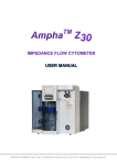
Figure 1: The Ampha Z30 Impedance Flow Cytometer System
1.2 Delivery and Inspection
The Ampha Z30 system includes AmphaSoft for controlling the instrument, data acquisition, and
data analysis, which runs on a Windows-based laptop PC with an USB-dongle for the software
license.
Carefully inspect all package boxes upon receipt of the cytometer. If there are any signs of
mishandling or damage, file a claim with the carrier immediately. If the shipment is separately
insured, file a claim with the insurer.
AMPHASYS AG s TECHNOPARK® Lucerne s Platz 4 s CH-6039 Root D4 s Switzerland s phone +41 41 541 91 20 s [email protected] s www.amphasys.com
3
User Manual Ampha Z30
1.3 Specifications
Impedance Chip
Channel dimensions
Impedance measurement
Frequency range
Frequency selection
Analysis range
Sample volume
Concentration range
Particle size
Fluidics
Sample flow rate
Pump
Labware compatibility
Operating System
Software
Dimensions
Weight
Operating Environment
Temperature
Humidity
Power
15 x 15 µm / 30 x 30 µm / 50 x 50 µm / 120 x 120 µm / 250 x 250
µm or other types on request depending on application
100 kHz – 30 MHz
Up to 4 different frequencies simultaneously
50 – 2000 µl
1 x 10³ to 1 x 10⁷ cells /ml
1 - 60 µm (up to 150 µm with 250 µm chip)
5 – 2500 µl/min, dependent on chip
Peristaltic pump with disposable pump head
5 ml polystyrene round-bottom tubes (Falcon® PP 352002/PS
352003/ Sarstedt PP 55.1579)
Windows 7 or 8
AmphaSoft, data in fcs3-format available
255 x 275 x 353 mm (W x D x H)
8.4 kg
16° - 32°C
10% - 90% relative non-condensing
24V DC ± 10%, max. 3A, < 90 W
Table 1: Specifications of Ampha Z30
2 Hazard and Precaution
This handbook contains information and warnings that must be followed by the user to ensure safe
operation of the instrument and to maintain the instrument in a safe condition. Possible hazards
that could harm the user or result in damage to the instrument are clearly stated at the appropriate
places throughout this handbook.
Before using the instrument it is essential to read this handbook carefully and to pay particular
attention to any advice it contains concerning hazards that may arise from use of the instrument.
Advices given in this handbook are intended to supplement, not supersede, the normal safety
requirements prevailing in the user’s country. Carry out the maintenance regularly in accordance
with the operating instructions. Amphasys will charge for repairs that prove to be required due to
incorrect maintenance.
2.1 Electrical Safety
To ensure satisfactory and safe operation of the instrument, it is essential that the neutral line
power cord is connected to true electrical earth (ground).
When working with the instrument:
• Make sure the line power cord is connected to a line power outlet that has a protective
conductor (earth/ ground).
• Do not attempt to make any internal adjustments or replacements.
AMPHASYS AG s TECHNOPARK® Lucerne s Platz 4 s CH-6039 Root D4 s Switzerland s phone +41 41 541 91 20 s [email protected] s www.amphasys.com
4
User Manual Ampha Z30
•
•
•
•
Do not operate the instrument with any covers or parts removed.
If water or reagent has spilled inside the instrument, switch off the instrument and
disconnect it from the line power supply. Contact Amphasys AG or the authorized
distributor.
Servicing should be carried out only by Amphasys AG or the authorized distributor.
If the instrument becomes electrically unsafe* for use, make the instrument inoperative and
secure it against unauthorized or unintentional operation. Contact Amphasys AG or the
authorized distributor.
*) The instrument is likely to be electrically unsafe when:
•
•
•
•
it shows visible damage,
the line power cord shows signs of damage,
it has been stored under unfavourable conditions for a prolonged period, or
it has been subjected to severe transport stresses.
WARNING:
ELECTRICAL HAZARD
The power supply is connected either at the rear of the instrument, or inside the instrument
housing (arrows in Fig. 2). The instrument is supplied with a 90W industrial adaptor power supply,
which provides output voltages of max. 24V. Therefore, no lethal voltages are supplied inside the
instrument.
However, any interruption of the protective conductor (earth/ground lead) of the AC power supply
cable or damage of the cable insulation is likely to make the instrument dangerous. Intentional
interruption is prohibited.
Use only the supplied power supply! Any other power supply might lead to an incorrect functioning
of the instrument or even to its damage.
Figure 2: Ampha Z30 rear side. Arrows indicate the plugs for the connection of the power supply.
AMPHASYS AG s TECHNOPARK® Lucerne s Platz 4 s CH-6039 Root D4 s Switzerland s phone +41 41 541 91 20 s [email protected] s www.amphasys.com
5
User Manual Ampha Z30
2.2 Biological Safety
WARNING:
SAMPLES CONTAINING INFECTIOUS AGENTS
If you use infectious agents with this instrument, handle such samples with the greatest of care and
in accordance with the required safety regulations. The responsible body (e.g. laboratory manager)
must take the necessary precautions to ensure that the surrounding work place is safe and that the
instrument operators are suitably trained and not exposed to hazardous levels of infectious agents
as defined in the applicable Materials Safety Data Sheets (MSDS) or other regulatory documents.
Disposal of wastes must be in accordance with all national, state, and local health and safety
regulations and laws.
WARNING:
WASTE DISPOSAL
Waste containers may contain hazardous chemicals or infectious agents from the process. Such
wastes must be collected and disposed of properly in accordance with the local safety regulations.
Refer to your local safety regulations for proper disposal procedures.
2.3 Chemicals
WARNING:
HAZARDOUS CHEMICALS
Some chemicals used with this instrument may be hazardous or may become hazardous after
completion of the protocol run (e.g. system cleaning solution). Always wear safety glasses, gloves,
and a lab coat. The responsible body (e.g., laboratory manager) must take the necessary
precautions to ensure that the surrounding work place is safe and that the instrument operators are
not exposed to hazardous levels of toxic substances (chemical or biological) as defined in the
applicable Materials Safety Data Sheets (MSDS) or other regulatory documents. Disposal of
wastes must be in accordance with all national, state, and local health and safety regulations and
laws.
AMPHASYS AG s TECHNOPARK® Lucerne s Platz 4 s CH-6039 Root D4 s Switzerland s phone +41 41 541 91 20 s [email protected] s www.amphasys.com
6
User Manual Ampha Z30
3 Setting up Ampha Z30
3.1 Installation
The instrument and the associated laptop PC are normally installed by Amphasys including some
general instructions and training.
3.1.1 Computer
Installation and operation of the instrument Ampha Z30 requires a separate laptop PC, which is
usually configured and supplied by Amphasys. The PC should be connected with the supplied
power cord to an AC power outlet 110-240V AC, 50/60Hz.
3.1.2 Software and Dongle
The instrument is operated with the software AmphaSoft, which is preinstalled with WindowsTM 7
on the PC. Update versions will be provided by Amphasys or can be downloaded from Amphasys’
website in the download area.
The use of AmphaSoft needs a license, which is provided with a USB-dongle. This dongle has
always to be plugged in the PC or laptop to be used with the software or instrument. Further details
are described in the AmphaSoft user guide.
3.1.3 Instrument
The instrument must be connected to an AC power outlet 110-240V AC, 50/60Hz. The power lines
to the equipment should be voltage regulated and surge protected. Connect the instrument with
the provided mini USB-cable to a USB-port of the PC (Fig. 2).
! Do not touch the gold contact pins in the lid and at the chip clamping system. For contacting
problems contact Amphasys.
! Always unplug all cables before moving the instrument or laptop to other tables etc.
To protect operating personnel, the National Electrical Manufacturers Association (NEMA)
recommends that the instrument is grounded correctly. The instrument is equipped with a 3
conductor AC power cord. When connected to an appropriate AC power outlet, ground the
instrument. To preserve this protection feature, do not operate the instrument from an AC power
outlet that has no grounding connection.
3.1.4 AmphaChips
The AmphaChips listed in table 2 are the actual available chips from Amphasys. In the table 2 is
also listed with which tubing set the chips can be applied and the recommended pump speeds for
running. Recommended particle concentration and sample filtration is given in table 3, section
3.2.2 .
Chip
specification
Chip channel
diameter
Fluidic set
Pump range
Measurement
pump speed
A00000
15 x 15 µm
S
1 – 50 rpm
10 – 20rpm
B00000
30 x 30 µm
M
1 – 300 rpm
30 – 50 µm
C00000
50 x 50 µm
M
1 – 300 rpm
80 (50 – 100) µm
D00000
120 x 120 µm
L
1 – 300 rpm
60 (50 – 100) rpm
E00000
250 x 250 µm
L
1 – 500 rpm
300 – 350 rpm
Table 3: AmphaChips, settings for fluidic set up.
AMPHASYS AG s TECHNOPARK® Lucerne s Platz 4 s CH-6039 Root D4 s Switzerland s phone +41 41 541 91 20 s [email protected] s www.amphasys.com
7
User Manual Ampha Z30
3.2 Measurement
All information about AmphaSoft is supplied in the separate AmphaSoft SW User Guide.
3.2.1 Start
·
! Check liquid bottles: The front bottle normally contains deionized water, the bottle at the
side is for waste liquid and should be possibly empty at the beginning of a test series. !
A
B
C
Figure 3: (A) Instrument, (B) Interface with chip, (C) Software shortcut icon on desktop
·
Switch on the instrument, the power switch is located at the back of the instrument. Turn on
the laptop PC. Make sure that the USB cable is correctly connected to your device and the
USB-dongle with the AmphaSoft software license is plugged in.
·
Start the software “AmphaSoft” by double clicking the icon (Fig. 3C).
·
Select your user mode, “Online” if you are connected to the
instrument and plan to perform a measurement, or “Offline”, if
you want to load and analyse data obtained from a former
experiment (Fig. 4).
Figure 4: Selection of online
or offline user mode.
·
AmphaSoft is started with a Main GUI (Fig. 5). All information how to use or measure with
AmphaSoft are explained in the AmphaSoft SW User Guide.
AMPHASYS AG s TECHNOPARK® Lucerne s Platz 4 s CH-6039 Root D4 s Switzerland s phone +41 41 541 91 20 s [email protected] s www.amphasys.com
8
User Manual Ampha Z30
Figure 5: AmphaSoft Main GUI.
·
Sample preparation: Make a single cell suspension in the correct buffer and filter the sample
with an appropriate filter. Cell dilution is dependent on chip channel diameter (Tab. 4).
Chip channel diameter
Recommended cell
concentration
Filter pore size
15 x 15 µm
1 – 40 Mio per ml
5 or 10 µm
30 x 30 µm
0.5 –10 Mio per ml
20 µm (30 µm)
50 x 50 µm
0.25 – 4 Mio per ml
30 – 40 µm
120 x 120 µm
1’000 – 200’000 per ml
50 - 70 µm (100 µm)
250 x 250 µm
1’000 – 50’000 per ml
150 µm (200 µm)
Table 4: Available AmphaChips, recommended cell concentrations for measurement and prefiltering.
AMPHASYS AG s TECHNOPARK® Lucerne s Platz 4 s CH-6039 Root D4 s Switzerland s phone +41 41 541 91 20 s [email protected] s www.amphasys.com
9
User Manual Ampha Z30
4 Maintenance
! The instrument cleaning cycle should be performed as a part of daily measurement routine after
the last measurement with AmphaClean solution as a cleaning detergent (Menu>Tools>Instrument
Cleaning).
Keep tubing’s clean to avoid contamination with microorganisms. To prevent microorganism
growth you can add Sodium Azide (NaN3) to the water bottle at concentrations of 0.01% or less
(! toxic compound!). Change the deionized water in the bottle regularly, especially before longer
disuse of the instrument.
Empty the waste bottle regularly and clean it, best each day to prevent growth of microorganisms
from back into the instrument.
In order to prevent system failures due to clogging, porous tubing’s or other problems with the
fluidic system it is necessary to exchange the peristaltic pump head, including the tubing’s, the
fluidic bottle filter and O-rings at least every two to three months. Shorter replacement cycles may
be necessary if the instrument is heavily used. Omitting the replacement of the fluidics set may
cause limited warranty.
The following table lists the parts and reagents that are required for regular maintenance (tab. 4).
More details are available at www.amphasys.com/community.
Part Number
12.100
12.030
12.015
19.012-S
19.012-L
21.900
11.901
Description
Fluidic Set L for 120/250 µm chips
Fluidic Set M for 30/50 µm chips
Fluidic Set S for 15 µm chips
Sample Tubing S
Sample Tubing L
AmphaClean (Cleaning buffer)
Chip Wash Station
Table 4: Accessories and replacement parts for maintenance.
4.1 Change and Replacement of Fluidic Set
The Fluidic Set (see Fig. 6) is supplied with different tubing dimensions (S, M, or L), depending on
the applications you are running on your device. The Fluidic Set was optimized and the Silicon
tubing’s and fittings have been adapted (Fig. 6).
AMPHASYS AG s TECHNOPARK® Lucerne s Platz 4 s CH-6039 Root D4 s Switzerland s phone +41 41 541 91 20 s [email protected] s www.amphasys.com
10
User Manual Ampha Z30
Clamp (r)
Clamp (l)
Barb Adapter
Figure 6: Fluidic Set including pump head left NEW, right OLD set.
4.1.1 Change from OLD to NEW Tubing Set
! With the change of the fluidic sets from old to new set, there is also a change of the Ampha Z30
internal fluidic by removing the check valve. For details you will be contacted by Amphasys or
please contact Amphasys. !
Before removing the old tubing set, make sure that the peristaltic pump is not running by checking
the software or looking at the pump head.
For changing the tubing set unscrew the three peek-fittings (Fig. 8A) from the old set and remove
all tubing’s from the valves. Take out the pump head by pressing the left and right clamp and lifting
the head (Fig. 6 and 7C). Place new tubing set with the pump head on the pump axis and press
down that the clamps snap into place (Fig. 7C).
Screw in the two new Barb Adapters (Fig. 6, 7 A/B). Press both silicone tubings, ending in a Yconnection, into the inner valve ports (back) and the two silicone tubing’s with direct connection
into the outer valve port (front, Fig. 7C, E, H). Screw the middle fitting (coming from Y-connector) in
the outer port of the instrument (Fig. 7F). To screw the fitting into the corresponding port, check
that the blue ferrule is flush with the tubing (Fig. 7D inlet). The peek nut should be loose at the
tubing. Insert the tubing with the ferrule in place into the receiving port and while holding the tubing
down firmly into the port, tighten the nut finger tight.
Push now the right silicone tubing on the barb adapter above the tube holder (Fig. 7F) and push
the left longer silicon tubing on the barb adapter in the instrument wall (Fig. 7G). Be sure that the
left longer silicone tubing has an easy loose knot, not pressing or squeezing the silicone tubing
(Fig. 7E, H). Place this tubing as in Figure 7H, don’t let it hang down.
Start the instrument and perform 2 to 3 times the rinsing program to fill the lines.
AMPHASYS AG s TECHNOPARK® Lucerne s Platz 4 s CH-6039 Root D4 s Switzerland s phone +41 41 541 91 20 s [email protected] s www.amphasys.com
11
User Manual Ampha Z30
A
C
D
B
E
F
H
G
Figure 7: Change of new peristaltic tubing set including pump head.
4.1.2 Replacement of New Tubing Set
Before removing the old tubing set, make sure that the peristaltic pump is not running by checking
the software or looking at the pump head.
For changing the tubing set unscrew the peek-fitting (Fig. 7D), drag down the both silicon tubing’s
from the barb adapters (Fig. 7F, D) and remove all tubing’s from the valves. Take out the pump
head by pressing the left and right clamp and lifting the head (Fig. 6 and 7C). Place new tubing set
with the pump head on the pump axis and press down that the clamps snap into place (Fig. 7C).
Press the both silicone tubing’s, ending in a Y-connection, in the inner valve ports and the both
silicone tubing’s with direct connection in the outer valve port (Fig. 7C, E, H). Screw the middle
fitting (coming from Y-connector) in the outer port of the instrument (Fig. 7F). To screw the fitting
into the corresponding port, check that the blue ferrule is flush with the tubing (Fig. 7D inlet). The
AMPHASYS AG s TECHNOPARK® Lucerne s Platz 4 s CH-6039 Root D4 s Switzerland s phone +41 41 541 91 20 s [email protected] s www.amphasys.com
12
User Manual Ampha Z30
peek nut should be loose at the tubing. Insert the tubing with the ferrule in place into the receiving
port and while holding the tubing down firmly into the port, tighten the nut finger tight.
Push now the right silicone tubing on the barb adapter above the tube holder (Fig. 7F) and push
the left longer silicon tubing on the barb adapter in the instrument wall (Fig. 7G). Be sure that the
left longer silicone tubing has an easy loose knot, not pressing or squeezing the silicone tubing
(Fig. 7E, H). Place this tubing as in Figure 7H, don’t let it hang down.
Start the instrument and perform 2 to 3 times the rinsing program to fill the lines.
4.1.3 Replacement of Old Tubing Set
Before removing the old tubing set, make sure that the peristaltic pump is not running by checking
the software or looking at the pump head.
For changing the tubing set unscrew the three peek-fittings (Fig. 8A), remove the tubings from the
valves. Take out the pump head by pressing the left and right clamp and lifting the head (Fig. 6 and
8B). Place new tubing set with the pump head on the pump axis and press down that the clamps
snap into place (Fig. 8C).
To screw the fittings into the corresponding ports, check that the blue ferrule is flush with the tubing
(Fig. 8D inlet). The peek nut should be loose at the tubing. Insert the tubing with the ferrule in place
into the receiving port and while holding the tubing down firmly into the port, tighten the nut finger
tight. Place the right fitting in the sample holder, the left fitting in the inner port (Fig. 8D). Press the
both silicone tubing’s, ending in a Y-connection, in the inner valve ports and the both silicone
tubing’s with direct connection in the outer valve port (Fig. 8E, F). Screw the middle fitting (coming
from Y-connector) in the outer port of the instrument (Fig. 8F).
Start the instrument and perform 2 to 3 times the rinsing program to fill the lines.
A
B
C
D
E
F
Figure 8: Change of old peristaltic tubing set including pump head.
AMPHASYS AG s TECHNOPARK® Lucerne s Platz 4 s CH-6039 Root D4 s Switzerland s phone +41 41 541 91 20 s [email protected] s www.amphasys.com
13
User Manual Ampha Z30
4.2 Replacement of Water Bottle Filter
We recommend to replace the fluidic bottle filter (Fig. 9A) quarterly together with the fluidic set. For
changing the bottle filter open the bottle and take it out from the instrument (Fig. 9B). Unscrew the
filter from the plastic fitting (Fig. 9 C+D). Check that the tubing in the fitting has overhang of about
3 mm (Fig. 9D). Then finger tighten the fitting into the new filter (Fig. 9 B+E), place the filter back in
the water filled bottle and close the lid. Perform 3 times the rinsing program to fill the filter and the
tubing.
A
C
E
B
D
Figure 9: Change of fluidic bottle filter.
4.3 Fluidic Processes in Ampha Z30
There are several automatic running fluidic processes regulated by the software. The way the fluid
moves, is explained below and shown in figure 10.
Rinsing / Flush: The left valve is switched and open in the back. The fluid runs first from the water
bottle through the tubing in the back of the left valve and the pump head to the sample tube. Then
you hear a click and both valves are switched left is open at front, right is open for back tubing.
Fluid is running from water bottle through right valve and the pump towards the chip and waste.
For Rinsing both processes run two times consecutive.
Measurement / Loading: Both valves are not active. The fluid is running from the sample tube
through the right valve, the pump and the left valve to the chip and waste. Loading is with high
speed of the pump and measurement with optimal speed for signal recording.
Cleaning: In the cleaning process for the daily shut down of the instrument first there is a rinsing
cycle, followed by loading the AmphaClean through the chip to the waste. Afterwards there is
running an additional rinsing cycle.
AMPHASYS AG s TECHNOPARK® Lucerne s Platz 4 s CH-6039 Root D4 s Switzerland s phone +41 41 541 91 20 s [email protected] s www.amphasys.com
14
User Manual Ampha Z30
A. Rinsing/Flush Part 1
B. Rinsing/Flush Part 2
C. Measurement (loading)
Pump – clockwise
Valve - left active
Pump – counter clockwise
Valve - right active
Pump – counter clockwise
Valve - no active
Figure 10: Picture with way of fluid on top, schematics of fluidic processes in Expert Window at the bottom.
When having problems with the fluidics, the Troubleshooting doesn’t help; the fluidic processes
can be regulated manually by using the expert window of AmphaSoft. The different possibilities are
shown in Figure 11, but handle with care and contact Amphasys if you are not confident with
functions.
AMPHASYS AG s TECHNOPARK® Lucerne s Platz 4 s CH-6039 Root D4 s Switzerland s phone +41 41 541 91 20 s [email protected] s www.amphasys.com
15
User Manual Ampha Z30
Sample to Chip
System liquid to Chip
System liquid circular
Sample to system liquid
Modes:
Sample loading
Measurement
Modes:
Rinsing/flushing chip
tubing
Cleaning system
Modes:
Not reasonable
Modes:
Not reasonable
Chip (waste) to system
liquid
System liquid to sample
Chip (waste) to sample
Sample to system liquid
Modes:
Not reasonable
Modes:
Rinsing/flushing sample
tubing
Cleaning sample tubing
Modes:
Not reasonable
Modes:
Not reasonable
Figure 11: Regulation of fluidic processes in Expert Window.
4.4 Chip cleaning
Chip insertion in chip holder:
· Keep the chip holder ready with the Amphasys sign facing upside.
· Take the chip with the holes facing down (the Amphasys logo is in the lower right side).
· Put the chip into the holder by carefully pressing the lateral clip until the chip is snapping in
its place (Fig. 12)
Figure 12: Placing the chip into chip holder.
AMPHASYS AG s TECHNOPARK® Lucerne s Platz 4 s CH-6039 Root D4 s Switzerland s phone +41 41 541 91 20 s [email protected] s www.amphasys.com
16
User Manual Ampha Z30
Chip cleaning and storing:
· The chips are delicate microfluidic devices. They should be handled with care, cleaned
regularly und stored in a dry and dust free box in the dark.
· The chip surface should be cleaned with a non-fuzzing tissue (e.g. Anticon® wipes) and
water, if needed. Use of fuzzing tissue may cause clogging of the microfluidic channel.
· Chips should be cleaned immediately after use. There are flush, rinse and wash cycles that
can be used while the chip is inserted in the instrument (see AmphaSoft User Guide).
Alternatively, the chips can be washed with filtered (<0.5 µm) high-purity water or mild
detergents (see below) in the chip wash station (Fig. 13) using a syringe (luer-lock
connection).
· When using the chip wash station, general chip cleaning of non-blocked chips should be
done from the inlet hole to the outlet hole. For de-blocking of clogged chips see instructions
below.
· Warning: Do not apply high pressure and do not use liquids with pH<6 and pH>8,
alcohols or any corrosive agents. Doing so can lead to the destruction of the chips.
A
B
C
Figure 13: Chip Wash Station, (A) placing of chip, (B) rinsing from inlet hole, (C) rinsing from outlet hole.
How to de-block clogged chips:
·
·
·
·
·
When chips are clogged by dust, cells or any other particles, we recommend the cleaning
procedure with the chip wash station mostly starting from the outlet hole (Fig. 13).
Cleaning should be started with <0.5 µm filtered high-purity water. If necessary, other
detergents can be used (see Tab. 5). Don’t rinse with any organic liquids like alcohols.
Checking the chip under a microscope usually helps to identify the cause of the clogging.
When there is a blocking between inlet and the sensing channel, rinse from outlet hole,
when there is a blocking between outlet hole and sensing channel, rinse from inlet hole.
After special cleaning procedures always rinse the chip with water from the inlet hole. Blow
out the water by pumping air through the chip wash station.
Detergents can also be warmed to about 40 to 50 degrees for better cleaning effects.
Detergent
<0.5 µm filtered high-purity water
<0.5 µm filtered 2% Neutracon or
solutions with dishwashing liquids
<0.5 µm filtered AmphaClean
Usage
· general cleaning liquid
· chip cleaning of persistent biological cell blockings or
residues in channels, holes
· detergents should be used for maximal 10 minutes, because
electrodes could be eroded after longer exposure
· chip cleaning of dirt and persistent biological cell blockings or
residues in channels, holes
Table 5: Chip cleaning detergents
AMPHASYS AG s TECHNOPARK® Lucerne s Platz 4 s CH-6039 Root D4 s Switzerland s phone +41 41 541 91 20 s [email protected] s www.amphasys.com
17
User Manual Ampha Z30
Additional tips for still blocked chips
· After cleaning with water, let the chip dry out overnight and try to clean again.
· Try with ultrasonic bath, take out the chip from the chip holder, put it for 1 minute in the bath
(containing clean water), put it back in the chip holder and try to clean again.
· If you know what kind of dirt is blocking the channel, you may try to dissolve the dirt with an
appropriate solution/detergent. Keep in mind that the chip, channel structure and electrodes
can be destroyed by certain chemicals. In case of doubt please contact Amphasys.
· Cleaning of the chip holes and channel with water or air and gentle pressure can be
generated by a normal plastic syringe with a small silicon tubing on the top. Pressing this at
the hole and either soaking or pressing can remove dirt (Fig. 14).
Figure 14: Syringe with silicone tubing for chip cleaning (left) and soaking at the inlet hole (right).
AMPHASYS AG s TECHNOPARK® Lucerne s Platz 4 s CH-6039 Root D4 s Switzerland s phone +41 41 541 91 20 s [email protected] s www.amphasys.com
18
User Manual Ampha Z30
5 Troubleshooting and technical support
5.1 Troubleshooting
The tables (Tab. 6 and 7) contain the basic troubleshooting guidelines. If problems persist after
performing troubleshooting, contact Amphasys Technical Support. Explanations and additional
troubleshooting using the Expert Window in AmphaSoft are marked with EW. Expert Window is
explained in detail in AmphaSoft User Guide.
When
Problem Problem
area
Cause
starting
AmphaSoft
software
General
Instrument not switched on or not connected to
the PC. Turn instrument on or connect USBcable and restart AmphaSoft or Communication
error
Communication error – closing process not
finished, wait always some seconds before
restart AmphaSoft
Restart
Error
during any
process
during
measurement
during fluid
process
the AmphaSoft program window does
not appear OR appears only for some
seconds
Closing of AmphaSoft and immediately
restart of the software – error message
A
Communication error – wrong data saving
A4
fluid process does not progress,
AmphaSoft programme does not
respond
fluid process stops abruptly
Electronics error
Communication error
B
A
Electronics error
Communication error
Fluidic problem
B
A
D
Chip blocking
Fluidic blocking
Measurement with special buffers (Ficoll,
sugars)
Bad electronic connections
Chip broken.
Chip blocking
Fluidic problem
Measurement with special buffers (Ficoll,
sugars)
Chip broken.
C
E
F
No water is running during Rinsing in the
sample tube or to waste, no flow
detected
after sample
loading
Signal
no signals are collected
Chip
A3
Communication error
No liquid
Signal
A
AmphaSoft doesn’t react, no response,
any running process stops and does not
progress
Measurement works only with low
processing, high rejection rate or
warnings/error messages of USB in log
window
No water
during
measurement
No in
Tab 7
signal collection stops after some time of
measurement
If the problem with the Chip cannot be
solved with any of the suggestions, put
in another chip and try measurement.
G
C
C
D
F
C
Contact Amphasys
Table 6: Problems with the system and during measurement.
No
A
Cause
1
2
Communication
error
Solution
What to do
exit AmphaSoft and turn off
instrument and PC, turn on
instrument and PC and restart
AmphaSoft
check USB connection from
instrument to PC
Success
question
If yes, go to
If no, go to
If exit of AmphaSoft is
not possible with normal
closing, stop process
with TaskManager
problem solved
A2
A1
contact Amphasys
AMPHASYS AG s TECHNOPARK® Lucerne s Platz 4 s CH-6039 Root D4 s Switzerland s phone +41 41 541 91 20 s [email protected] s www.amphasys.com
19
User Manual Ampha Z30
No
B
Cause
Solution
What to do
3
Communication
error - speed
4
Communication
error – low
processing
1
2
Electronics error
Electronics error
exit AmphaSoft and restart it
exit AmphaSoft and turn off
instrument and PC, turn on
instrument and PC and restart
AmphaSoft
Chip broken
Chip was tested , is broken or
no solution found – inform
Amphasys
Chip blocking
take out chip, put chip in
rinsing device or look directly
at it under the microscope
rinse the chip from the front
hole with the syringe and (0.2
µm-filtered!) distilled water.
rinse the chip from the back
hole with the syringe and
(0.2um-filtered!) distilled
water.
use other filtered liquids to
rinse, from the back or from
the front: mild detergent or
alcohol (see Tab. 4)
fill chip with AmphaClean,
incubate for 30 min maximum,
rinse thoroughly with water
wait until the chip channels
are dry
C
1
1.1
1.2
2.1
2.2
2.3
2.4
Close the popup windows by
confirming and press ESC,
restart AmphaSoft
During measurement save
data only locally at the laptop,
don’t use server connections
for saving
Success
question
If yes, go to
If no, go to
problem solved
A1
problem solved
contact Amphasys
problem solved
B1
B2
contact Amphasys
no blocking visible in
front of the narrow
channel?
water comes out at the
tube connected to the
chip outlet hole?
water comes out at the
tube connected to the
chip inlet hole?
C1.1
Use another chip,
broken chips
discard, for chips
with problem
contact
Amphasys.
C1.2
problem solved
C1.2
C1
C2.1
liquid comes out at the
tubes connected to the
chip holes?
C1.1
C2.2
all cell-derived blockings
are dispersed?
C1.1
C2.3, C2.4, C2.5
Measurement works
now with normal process
speed and without any
warnings or error
messages
C1.1
push air through the chip with
the syringe
fill the chip with water, put it in
distilled water in an ultrasonic
bath for 1 to 2 minutes
2.5
C1.1
C1.1
Use another chip,
for chips with
problem contact
Amphasys
fill the water bottle
and run 3 times
Rinsing
problem solved
D2
problem solved
Try with section
4.3 or contact
Amphasys for
further instructions
fill the water bottle
and run 3 times
rinsing
E2
Attention: sample will be washed away during the following steps.
D
E
1
check liquid bottles
Is water liquid bottle run
dry?
2
Water bottle is full, but tubing
is empty?
3
Check if valves are functional,
any dried sugar solutions
within the valves from
clogging problems can stop
the switching
Check if fitting to the
bottle is fixed, Fig. 7,
check connection of
water filter in the bottle
to the tubing Fig. 8 C/D,
perform Rinsing
Clean the valves
including the tubings
outside with water,
perform Rinsing and
observe valve switching
1
Fluidic problem
Fluidic blocking
check liquid bottles
Is water liquid bottle run
dry?
D3
Use expert window
AMPHASYS AG s TECHNOPARK® Lucerne s Platz 4 s CH-6039 Root D4 s Switzerland s phone +41 41 541 91 20 s [email protected] s www.amphasys.com
20
User Manual Ampha Z30
No
Cause
EW
2
EW
3
EW
3.1
EW
3.2
4
4.1
4.2
F
1
Cell
sedimentation
2.1
2.2
G
1
1.1
1.2
1.3
Bad electronic
connections
Solution
What to do
Success
question
If yes, go to
If no, go to
take out chip, put pump speed
to 100 rpm, make sure to
have liquid from sample
loading, if not select right
valve to switch to system
water
Check left valve, uncheck
right valve, check pump to
clockwise (right button) put
pump speed to 100 rpm
Unscrew fitting from tubing set
to the chip (left, inner port),
insert sample tube with water,
uncheck valves, put pump
speed to 100rpm or check
right valve to use with system
water
take out chip, unscrew a fitting
with tubing from the cleaning
device, screw it in the port to
the chip, connect syringe to
this tubing and try to push
water
Unscrew fitting from tubing set
to the chip (left, inner port),
insert tube with water,
uncheck valves, put pump
speed to 100rpm
Check tubing set for blocking,
gaps etc.
Unscrew all fittings from
tubing set, rinse carefully with
syringe from cleaning device
from all fittings
Follow air gapes in the
tubing to see liquid
running; liquid comes
out at the chip inlet Oring?
problem solved,
dry chip area, put
in cleaned chip,
uncheck valve and
go on with your
measurements
Yes, put valve and
pump selection
back E3.1
E3
E3.2
E4
Water comes out at chip
inlet O-ring?
Put all fittings back
to their port, E2
Blocked check
valve, exchange
or cleaning
necessary contact
Amphasys
Liquid comes out at
unscrewed fitting
Yes, screw fitting,
E3.2
E4.1
Visible problems or
breaks
Liquid drops at all sides
new tubing set
necessary
Yes, screw in
system, E2
E4.2
try to measure cells at higher
speed, EW, adjust pump
speed
sedimentation will appear
further, use high concentrated
samples and short
measurement times, stay with
higher pump speed
dissolve sample in more
viscous liquid: prepare a
solution with Ficoll400 (1015%) in buffer (this slows
down the fluidics, adjust pump
speed in EW, rinse well
afterwards)
EW, adjust pump speed,
Cell sedimentation is
reduced
problem solved,
F2.1
F2.2
Cell sedimentation is
reduced to an
acceptable level?
problem solved
contact Amphasys
Measurements are
okay?
problem solved
G1.2
Measurements are
okay?
problem solved
G1.3
Measurements are
okay?
problem solved
G2
take out chip, try the following
things:
dry electrical connections on
chip and in the instrument
with the special clean room
towel provided
clean electrical connections
on chip and in instrument with
Acetone
Examine electrical spring
contacts in the instrument to
find out whether they are bent
and do not contact the pads
on the chip any more or
whether they are even
broken. Try to bend them
carefully to a good chip
contacting position.
Follow air gapes in the
tubing’s to see liquid
running; liquid comes
out at sample loading
Liquid comes out at
unscrewed fitting
E4
new tubing set
necessary
AMPHASYS AG s TECHNOPARK® Lucerne s Platz 4 s CH-6039 Root D4 s Switzerland s phone +41 41 541 91 20 s [email protected] s www.amphasys.com
21
User Manual Ampha Z30
No
Cause
2
Solution
What to do
Put in another chip and try
again.
Success
question
If yes, go to
If no, go to
Measurements are
okay?
problem solved,
The first chip was
broken.
Try with another
chip. If
measurements are
bad, contact
Amphasys
Table 7: Possible solutions of problems listed in Tab. 6
5.2 Limited Warranty
Limited warranty period is one (1) year from first operation of the Product by Buyer. It covers
software and firmware, and defects in material and workmanship under normal use and does not
apply to ordinary wear and tear. For detailed information, refer to the warranty information at
www.amphasys.com.
5.3 Extended Warranties
Extended warranties are available. Visit www.amphasys.com for information.
5.4 Technical Support
For technical support, contact:
Amphasys AG
Technopark Lucerne
Platz 4
CH-6039 Root D4, Switzerland
Phone: +41 41 541 91 20
Email: [email protected]
5.5 Ordering Information
For a complete list of parts and reagents, please visit www.amphasys.com.
AMPHASYS AG s TECHNOPARK® Lucerne s Platz 4 s CH-6039 Root D4 s Switzerland s phone +41 41 541 91 20 s [email protected] s www.amphasys.com
22