1
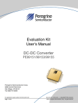
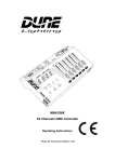
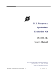
PE43713 Evaluation Kit (EVK) User’s Manual
UltraCMOS® RF Digital Step Attenuator, 9 kHz–6 GHz
DOC-65453-1 – (3/2015)
EVK User’s Manual
www.psemi.com
PE43713
Evaluation Kit (EVK) User’s Manual
Copyright and Trademarks
©2015, Peregrine Semiconductor Corporation. All rights reserved. The Peregrine name, logo, UTSi and
UltraCMOS are registered trademarks and HaRP, MultiSwitch and DuNE are trademarks of Peregrine Semiconductor Corp.
Disclaimers
The information in this document is believed to be reliable. However, Peregrine assumes no liability for the use
of this information. Use shall be entirely at the user’s own risk. No patent rights or licenses to any circuits
described in this document are implied or granted to any third party. Peregrine’s products are not designed or
intended for use in devices or systems intended for surgical implant, or in other applications intended to support
or sustain life, or in any application in which the failure of the Peregrine product could create a situation in which
personal injury or death might occur. Peregrine assumes no liability for damages, including consequential or
incidental damages, arising out of the use of its products in such applications.
Patent Statement
Peregrine products are protected under one or more of the following U.S. patents: patents.psemi.com
Sales Contact
For additional information, contact Sales at [email protected].
Corporate Headquarters
9369 Carroll Park Drive, San Diego, CA, 92121
858-731-9400
Page ii
DOC-65453-1 – (3/2015)
www.psemi.com
PE43713
Evaluation Kit User’s Manual
Table of Contents
Introduction - - - - - - - - - - - - - - - - - - - - - - - - - - - - - - - - - - - - - - - - - - - - - - - - - - - - - - 1
Introduction - - - - - - - - - - - - - - - - - - - - - - - - - - - - - - - - - - - - - - - - - - - - - - - - - - - - - - - - - - - - - - - - - - - - - - 1
Application Support . . . . . . . . . . . . . . . . . . . . . . . . . . . . . . . . . . . . . . . . . . . . . . . . . . . . . . . . . . . . . . . . . . . . . . . . . . . . . . . . . . 1
Evaluation Kit Contents and Requirements . . . . . . . . . . . . . . . . . . . . . . . . . . . . . . . . . . . . . . . . . . . . . . . . . . . . . . . . . . . . . 1
Kit Contents . . . . . . . . . . . . . . . . . . . . . . . . . . . . . . . . . . . . . . . . . . . . . . . . . . . . . . . . . . . . . . . . . . . . . . . . . . . . . . . . . . . . . . . . . . . . . . . . . . . . 1
Software Requirements . . . . . . . . . . . . . . . . . . . . . . . . . . . . . . . . . . . . . . . . . . . . . . . . . . . . . . . . . . . . . . . . . . . . . . . . . . . . . . . . . . . . . . . . . . 2
Hardware Requirements . . . . . . . . . . . . . . . . . . . . . . . . . . . . . . . . . . . . . . . . . . . . . . . . . . . . . . . . . . . . . . . . . . . . . . . . . . . . . . . . . . . . . . . . . 2
Evaluation Board Assembly - - - - - - - - - - - - - - - - - - - - - - - - - - - - - - - - - - - - - - - - - - 3
Evaluation Board Assembly Overview - - - - - - - - - - - - - - - - - - - - - - - - - - - - - - - - - - - - - - - - - - - - - - - - - - 3
Quick Start Guide - - - - - - - - - - - - - - - - - - - - - - - - - - - - - - - - - - - - - - - - - - - - - - - - - 5
Quick Start Guide Overview - - - - - - - - - - - - - - - - - - - - - - - - - - - - - - - - - - - - - - - - - - - - - - - - - - - - - - - - - - 5
Software Installation - - - - - - - - - - - - - - - - - - - - - - - - - - - - - - - - - - - - - - - - - - - - - - - - - - - - - - - - - - - - - - - 5
USB Driver . . . . . . . . . . . . . . . . . . . . . . . . . . . . . . . . . . . . . . . . . . . . . . . . . . . . . . . . . . . . . . . . . . . . . . . . . . . . . . . . . . . . . . . . . . . . 5
EVK Software . . . . . . . . . . . . . . . . . . . . . . . . . . . . . . . . . . . . . . . . . . . . . . . . . . . . . . . . . . . . . . . . . . . . . . . . . . . . . . . . . . . . . . . . . 5
Hardware Configuration - - - - - - - - - - - - - - - - - - - - - - - - - - - - - - - - - - - - - - - - - - - - - - - - - - - - - - - - - - - - 8
USB Interface Board Overview . . . . . . . . . . . . . . . . . . . . . . . . . . . . . . . . . . . . . . . . . . . . . . . . . . . . . . . . . . . . . . . . . . . . . . . . . 8
Connection of the USB Interface Board to the Evaluation Board . . . . . . . . . . . . . . . . . . . . . . . . . . . . . . . . . . . . . . . . . . 8
Evaluation Board Overview . . . . . . . . . . . . . . . . . . . . . . . . . . . . . . . . . . . . . . . . . . . . . . . . . . . . . . . . . . . . . . . . . . . . . . . . . . . . 9
Hardware Operation . . . . . . . . . . . . . . . . . . . . . . . . . . . . . . . . . . . . . . . . . . . . . . . . . . . . . . . . . . . . . . . . . . . . . . . . . . . . . . . . . 11
Using the Graphical User Interface - - - - - - - - - - - - - - - - - - - - - - - - - - - - - - - - - - - - - - - - - - - - - - - - - - - - 12
Technical Resources - - - - - - - - - - - - - - - - - - - - - - - - - - - - - - - - - - - - - - - - - - - - - - - 17
Technical Resources - - - - - - - - - - - - - - - - - - - - - - - - - - - - - - - - - - - - - - - - - - - - - - - - - - - - - - - - - - - - - - - 17
DOC-65453-1 – (3/2015)
Page 1
www.psemi.com
PE43713
Evaluation Kit User’s Manual
Page 2
DOC-65453-1 – (3/2015)
www.psemi.com
PE43713
Evaluation Kit User’s Manual
Introduction
1
Introduction
The PE43713 is a 50Ω HaRP™ technology-enhanced, 7-bit RF digital step attenuator (DSA) designed for use in
3G/4G wireless infrastructure and other high performance RF applications. An integrated digital control interface
supports both serial and parallel programming of the attenuation. Covering a 31.75 dB attenuation range in
0.25 dB steps, it maintains high linearity and low power consumption from 9 kHz through 6 GHz. PE43713
features glitch-less attenuation state transitions and is offered in a 32-lead 5 × 5 mm QFN package. In addition,
no external blocking capacitors are required if 0 VDC is present on the RF ports.
The PE43713 evaluation kit (EVK) includes the application software and hardware required to control and
evaluate the functionality of the DSA using a PC running the Windows operating system to control the USB
interface board. The EVK can also be operated manually. Refer to “Hardware Operation" in Chapter 3,
page 11 for instructions on manually programming the EVK in Direct Parallel mode.
Application Support
For any technical inquiries regarding the evaluation kit or software, please visit applications support at
www.psemi.com (fastest response) or call (858) 731-9400.
Evaluation Kit Contents and Requirements
Kit Contents
The PE43713 Evaluation Kit (EVK) includes all of the specific software and hardware required to evaluate the
DSA. Included in the EVK are:
Table 1 • PE43713 Evaluation Kit Contents
Quality
Description
1
PE43713 DSA Evaluation Board Assembly (PRT-45305)
1
Peregrine USB Interface Board Assembly (PRT-50446)
1
USB 2.0 Type A to Type B Mini Cable
DOC-65453-1 – (3/2015)
Page 1
www.psemi.com
PE43713
Evaluation Kit User’s Manual
Software Requirements
The application software will need to be installed on a computer with the following minimum requirements:
• PC compatible with Windows™ XP, Vista, 7 or 8
• Mouse
• USB port
• HTML browser with internet access
• Administrative privileges
Hardware Requirements
In order to evaluate the step attenuation performance of the evaluation board, the following equipment is
required:
• DC power supplies and DC cables
• Vector network analyzer
Caution: The PE43713 DSA EVK contains components that might be damaged by exposure to voltages in
excess of the specified voltage, including voltages produced by electrostatic discharges. Handle the board in
accordance with procedures for handling static-sensitive components. Avoid applying excessive voltages to the
power supply terminals or signal inputs or outputs.
Page 2
DOC-65453-1 – (3/2015)
www.psemi.com
PE43713
Evaluation Kit User’s Manual
Evaluation Board Assembly
2
Evaluation Board Assembly Overview
The evaluation board is assembled with a PE43713 DSA, SP2T mechanical switch (P/S), SP3T mechanical
switches (D0–D6,LE), several headers and SMA connectors. The P/S switch is used for Parallel or Serial mode
selection. The D0–D6,LE switches are used for setting the control bits in Direct Parallel programming mode.
Figure 1 • PE43713 Evaluation Board Assembly
DOC-65453-1 – (3/2015)
Page 3
www.psemi.com
PE43713
Evaluation Kit User’s Manual
Page 4
DOC-65453-1 – (3/2015)
www.psemi.com
PE43713
Evaluation Kit User’s Manual
Quick Start Guide
3
Quick Start Guide Overview
The digital attenuator evaluation board (EVB) was
designed to ease customer evaluation of the PE43713
digital step attenuator. This chapter will guide the user
through the software installation, hardware configuration and using the graphical user interface (GUI).
Windows™ XP, Vista, 7 or 8. This software is
available directly from Peregrine’s website at
www.psemi.com.
To install the DSA evaluation software, unzip the
archive and execute the “setup.exe.”
Figure 3 • DSA Evaluation Software Installer
Software Installation
USB Driver
The latest USB interface board drivers are available
via Microsoft Windows update. Internet connectivity is
required to download the drivers. Connect the USB
interface board to the PC and select the Windows
Update option to obtain and install the drivers.
If the USB board drivers are not installed, it will not be
possible to run the program correctly. A USB interface
board (Figure 2) is included in the evaluation kit.
After the setup.exe file has been executed, a welcome
screen will appear. It is strongly recommended that all
programs be closed prior to running the install
program. Click the “Next>” button to proceed.
Figure 4 • DSA Evaluation Software Setup
Figure 2 • DSA USB Driver Installation
EVK Software
In order to evaluate the PE43713 performance, the
application software has to be installed on your
computer. The USB interface and DSA application
software is compatible with computers running
DOC-65453-1 – (3/2015)
Page 5
www.psemi.com
PE43713
Evaluation Kit User’s Manual
Take a moment to read the license agreement, then
click “I Agree” and “Next>.”
In the window of Confirm Installation, click “Next>” to
proceed with the software installation.
Figure 5 • License Agreement
Figure 7 • Confirm Installation
For most users the default install location for the
program files is sufficient. If a different location is
desired, the install program can be directed to place
the program files in an alternate location. The
software is installed for “Everyone” by default. Once
the desired location is selected click “Next>.”
As the software files are installed, a progress indicator
will be displayed. On slower computers, installation of
the software may proceed for a few moments.
Figure 8 • Progress Indicator
Figure 6 • Select Installation Folder
Page 6
DOC-65453-1 – (3/2015)
www.psemi.com
PE43713
Evaluation Kit User’s
Once the evaluation software is installed, click “Close”
to exit.
Figure 9 • Installation Complete
A new Start Menu item under Peregrine Semiconductor will appear in the start menu of your computer.
Select “DSA Evaluation Software” to launch the GUI.
Figure 10 • DSA Evaluation Software Launch
DOC-65453-1 – (3/2015)
Page 7
www.psemi.com
PE43713
Evaluation Kit User’s Manual
Hardware Configuration
USB Interface Board Overview
A USB interface board (Figure 11) is included in the evaluation kit. This board allows the user to send serial
peripheral interface (SPI) commands to the device under test by using a PC running the Windows™ operating
system. To install the software, extract the zip file to a temporary directory and follow the installation procedure
included.
Figure 11 • DSA USB Interface Board
Connection of the USB Interface Board to the Evaluation Board
The evaluation board and the USB interface board contain a keyed 16 pin header. This feature allows the USB
interface board (socket) to connect directly to the evaluation board (pin) on the front-side as shown in Figure 12.
Figure 12 • USB Interface Board Connected to the Evaluation Board for Latched Parallel and Serial Programming
Page 8
DOC-65453-1 – (3/2015)
www.psemi.com
PE43713
Evaluation Kit User’s
Evaluation Board Overview
The evaluation board is designed to ease customer evaluation of Peregrine’s products. The board contains:
1) Digital signal connectors that are connected for power supply, digital control signals and USB interface board.
2) SMA connectors that are connected for RF performance verification and THRU trace to calibrate board trace
loss.
The schematic and evaluation board outline are provided in this user manual.
Figure 13 • PE43713 Evaluation Board Schematic
P/S
J5
1
C0_25
4
3
C0_5
6
5
C1
8
7
C2
10
9
C4
12
11 C8/CLK
14
13 C16/DATA
16
15
6
C1
C2
C3
C4
C5
100pF
100pF
100pF
100pF
100pF
2 2
JP2
R2
DNI
R3
DNI
D1
1
3
2
JP4
D2
1
3
2
D3
1
3
2
1 1
4
C6
C7
100pF
100pF
4
1 1
D4
1
2 2
3
2
4
LE
23
3
PS
A1
22
4
A0
A2
21
GND
GND
17
J4
Z=50 Ohm
1
2
3
4
2
LE
1
3
2
4
A0
A1
16
GND
15
12
14
13
J2
Z=50 Ohm
VDD_DIG
VDD
HDR3
1
3
4
HDR1
1
THRU
D6
DNI
GND
8
GND
18
GND
RF2
GND
GND
RF1
GND
GND
7
GND
R1
VSS_EXT 20
19
2
2
VSS
3
VSS
2
3
DNI
C8
C10
0.1µF
C9
A2
1
VDD_DIG
HDR2
IN1 2
GND
6
1
3
4
A2
IN3 8
U1
PE43713
D5
A1
IN2 5
26
SI 25
28
29
27
C8
C16
C4
C2
31
30
VDD
2
9
Z=50 Ohm
C1
24
GND
5
J1
C0.5
CLK
1
GND
A0
C0.25
32
0 OHM
VDD
J3
2
4
JP3
1 1
11
2 2
1
3
LE
10
1 1
D0
4
2 2
JP1
VDD_DIG
4
5
2
3 VDD1
GND1 1
6 VDD2
GND2 4
9 VDD3
GND3 7
100pF
100pF
C11
100pF
C13
0.1µF
DOC-65453-1 – (3/2015)
Page 9
www.psemi.com
PE43713
Evaluation Kit User’s Manual
Figure 14 • PE43713 Evaluation Board Outline Showing Functional Overview
USB Interface Board
Connector
“Low” in Direct Parallel Mode
Programming Switches
Set for Latched Parallel/Serial Mode
“High” in Direct Parallel Mode
Apply
External
Power
Supply
VSS and GND
Connect Together
Serial Addressable Jumper
VDD and VDD_DIG
Connect Together
Parallel/Serial Mode Selection
RF In/Out
RF In/Out
“THRU” trace is for board trace loss calibration
Page 10
DOC-65453-1 – (3/2015)
www.psemi.com
PE43713
Evaluation Kit User’s
Hardware Operation
The general guidelines for operating the hardware evaluation board are listed in this section. Follow the steps
below to configure the hardware properly for the performance.
1) Verify that all DC power supplies are turned off before proceeding.
2) Connect the jumper on JP2, JP3 and JP4.
3) Place the three jumpers of HDR2 connecting the middle pin to the GND pin. HDR2 is for the serial-addressable features. Refer to the PE43713 datasheet for more details.
4) Position the P/S switch to Parallel or Serial mode.
5) Set the D0–D6 and LE mechanical programming switches on the board to support Direct Parallel, Latched
Parallel or Serial mode.
a) Place D0–D6 and LE at the middle position to support Latched Parallel and Serial modes with GUI application software and proper position of the P/S switch.
b) In Direct Parallel mode, D0–D6 can be set to HIGH or LOW to manually program the attenuation state
while LE is connected to HIGH without using the USB interface board and GUI application software.
6) Provide external power supply to the HDR3 (Table 2).
a) VDD is the positive power supply with 3.0V typical.
b) VDD_DIG is the positive power supply for control signals with 1.8V typical, and it can be connected to VDD
with jumper to simplify the test set-up.
c) VDD_DIG can be connected to VDD with jumper to simplify the test set-up, VDD_DEG = VDD = 3.0V
typical.
d) VSS is the external negative power supply for PE43713. It can also be short to GND using the internal
negative voltage generator to simplify the test setup.
7) Calibrate board trace loss with THRU trace between J3 and J4.
Table 2 • Operating Ranges
Parameter
Supply voltage, VDD
Min
Typ
2.3
Supply current, IDD
150
Max
Unit
5.5
V
200
µA
Digital input high
1.17
3.6
V
Digital input low
–0.3
0.6
V
17.5
µA
Digital input current
DOC-65453-1 – (3/2015)
Page 11
www.psemi.com
PE43713
Evaluation Kit User’s Manual
Using the Graphical User Interface
Figure 15 displays the DSA application software graphical user interface (GUI), which has the USB interface
board plugged into the computer. “Hardware Operation” for the EVK hardware configuration to use with the GUI
control software. If the USB interface board is not connected when the application software is launched, the
message “No interface board connected! Please connect USB-SPI Interface #101-0695.” will appear at the
bottom of the screen.
In the upper left corner, under the Peregrine logo there is a drop down menu item to select the part for evaluation and the part description is below the part number box.
Figure 15 • DSA Application Software Graphical User Interface
Page 12
DOC-65453-1 – (3/2015)
www.psemi.com
PE43713
Evaluation Kit User’s
The DSA application software GUI supports Latched Parallel and Serial modes with position of the P/S switch
(Table 3), and shows the control bit waveform at the right side of the GUI when the mode is selected.
Table 3 • EVK Jumper/Switch Configuration
GUI Operation
Jumper/Switch
Direct Parallel Mode
Latched Parallel Mode
Serial Mode
P/S
P
P
S
LE
HIGH
EXT
EXT
D0
LOW/HIGH
EXT
EXT
D1
LOW/HIGH
EXT
EXT
D2
LOW/HIGH
EXT
EXT
D3
LOW/HIGH
EXT
EXT
D4
LOW/HIGH
EXT
EXT
D5
LOW/HIGH
EXT
EXT
D6
LOW/HIGH
EXT
EXT
JP2
Installed
Installed
Installed
JP3
Installed
Installed
Installed
JP4
Installed
Installed
Installed
DOC-65453-1 – (3/2015)
Page 13
www.psemi.com
PE43713
Evaluation Kit User’s Manual
The Send button changes functionality based on the control interface mode. Send Latch in Latched Parallel
mode and Send Signal in Serial mode are provided to resend the programming bits to the device at the same
attenuation state.
Figure 16 • Latched Parallel or Serial Mode
Continuous Pattern Loop can be selected to automatically step through each of the attenuation states.
Figure 17 • Continuous Pattern Loop
The Attenuation Value box displays the attenuation
value the DSA is currently programmed to. The user
can enter the desired attenuation value followed by
the “Enter” key to program the DSA.
Figure 18 • Attenuation Value
Page 14
DOC-65453-1 – (3/2015)
www.psemi.com
PE43713
Evaluation Kit User’s
The center of the GUI is the attenuation slide bar that allows the user to quickly select the desired attenuation.
The arrows at the top and bottom can be clicked to increase or decrease attenuation state at the minimum step
size.
Figure 19 • Attenuation Slide Bar
DOC-65453-1 – (3/2015)
Page 15
www.psemi.com
PE43713
Evaluation Kit User’s Manual
Page 16
DOC-65453-1 – (3/2015)
www.psemi.com
PE43713
Evaluation Kit User’s Manual
Technical Resources
4
Technical Resources
Additional technical resources are available for download in the Products section at www.psemi.com. These
include the Product Specification datasheet, S-parameters zip file, evaluation kit schematic and bill of materials,
material declaration form and PC-compatible software file.
Trademarks are subject to trademark claims.
DOC-65453-1 – (3/2015)
Page 17
www.psemi.com
PE43713
Evaluation Kit User’s Manual
Page 18
DOC-65453-1 – (3/2015)
www.psemi.com
PE43713
Evaluation Kit User’s Manual
Document Categories
Advance Information
The product is in a formative or design stage. The datasheet contains design target specifications for product
development. Specifications and features may change in any manner without notice.
Preliminary Specification
The datasheet contains preliminary data. Additional data may be added at a later date. Peregrine reserves the
right to change specifications at any time without notice in order to supply the best possible product.
Product Specification
The datasheet contains final data. In the event Peregrine decides to change the specifications, Peregrine will
notify customers of the intended changes by issuing a CNF (Customer Notification Form).
Not Recommended for New Designs (NRND)
This product is in production but is not recommended for new designs.
End of Life (EOL)
This product is currently going through the EOL process. It has a specific last-time buy date.
Obsolete
This product is discontinued. Orders are no longer accepted for this product.
DOC-65453-1 – (3/2015)
Page 19
www.psemi.com
PE43713
Evaluation Kit User’s Manual
DOC-65453-1 – (3/2015)
Page 20
www.psemi.com