1
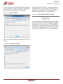
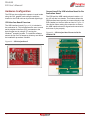
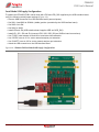
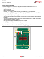
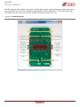
PE44820 Evaluation Kit (EVK) User’s Manual
UltraCMOS® RF Digital Phase Shifter
PE44820
Evaluation Kit
DOC-68986-2 – (08/2015)
EVK User’s Manual
www.psemi.com
PE44820
Evaluation Kit (EVK) User’s Manual
Copyright and Trademarks
©2015, Peregrine Semiconductor Corporation. All rights reserved. The Peregrine name, logo, UTSi and
UltraCMOS are registered trademarks and HaRP, MultiSwitch and DuNE are trademarks of Peregrine Semiconductor Corp.
Disclaimers
The information in this document is believed to be reliable. However, Peregrine assumes no liability for the use
of this information. Use shall be entirely at the user’s own risk. No patent rights or licenses to any circuits
described in this document are implied or granted to any third party. Peregrine’s products are not designed or
intended for use in devices or systems intended for surgical implant, or in other applications intended to support
or sustain life, or in any application in which the failure of the Peregrine product could create a situation in which
personal injury or death might occur. Peregrine assumes no liability for damages, including consequential or
incidental damages, arising out of the use of its products in such applications.
Patent Statement
Peregrine products are protected under one or more of the following U.S. patents: patents.psemi.com
Sales Contact
For additional information, contact Sales at [email protected].
Corporate Headquarters
9369 Carroll Park Drive, San Diego, CA, 92121
858-731-9400
Page ii
DOC-68986-2 – (08/2015)
www.psemi.com
PE44820
EVK User’s Manual
Table of Contents
Introduction - - - - - - - - - - - - - - - - - - - - - - - - - - - - - - - - - - - - - - - - - - - - - - - - - - - - - - 1
Introduction - - - - - - - - - - - - - - - - - - - - - - - - - - - - - - - - - - - - - - - - - - - - - - - - - - - - - - - - - - - - - - - - - - - - - - 1
Application Support . . . . . . . . . . . . . . . . . . . . . . . . . . . . . . . . . . . . . . . . . . . . . . . . . . . . . . . . . . . . . . . . . . . . . . . . . . . . . . . . . . 1
Evaluation Kit Contents and Requirements . . . . . . . . . . . . . . . . . . . . . . . . . . . . . . . . . . . . . . . . . . . . . . . . . . . . . . . . . . . . . 1
Kit Contents . . . . . . . . . . . . . . . . . . . . . . . . . . . . . . . . . . . . . . . . . . . . . . . . . . . . . . . . . . . . . . . . . . . . . . . . . . . . . . . . . . . . . . . . . . . . . . . . . . . . 1
Software Requirements . . . . . . . . . . . . . . . . . . . . . . . . . . . . . . . . . . . . . . . . . . . . . . . . . . . . . . . . . . . . . . . . . . . . . . . . . . . . . . . . . . . . . . . . . . 2
Hardware Requirements . . . . . . . . . . . . . . . . . . . . . . . . . . . . . . . . . . . . . . . . . . . . . . . . . . . . . . . . . . . . . . . . . . . . . . . . . . . . . . . . . . . . . . . . . 2
Evaluation Board Assembly - - - - - - - - - - - - - - - - - - - - - - - - - - - - - - - - - - - - - - - - - - 3
Evaluation Board Assembly Overview - - - - - - - - - - - - - - - - - - - - - - - - - - - - - - - - - - - - - - - - - - - - - - - - - - 3
Quick Start Guide - - - - - - - - - - - - - - - - - - - - - - - - - - - - - - - - - - - - - - - - - - - - - - - - - 5
Quick Start Overview - - - - - - - - - - - - - - - - - - - - - - - - - - - - - - - - - - - - - - - - - - - - - - - - - - - - - - - - - - - - - - - 5
Software Installation - - - - - - - - - - - - - - - - - - - - - - - - - - - - - - - - - - - - - - - - - - - - - - - - - - - - - - - - - - - - - - - 5
USB Driver . . . . . . . . . . . . . . . . . . . . . . . . . . . . . . . . . . . . . . . . . . . . . . . . . . . . . . . . . . . . . . . . . . . . . . . . . . . . . . . . . . . . . . . . . . . . 5
EVK Software . . . . . . . . . . . . . . . . . . . . . . . . . . . . . . . . . . . . . . . . . . . . . . . . . . . . . . . . . . . . . . . . . . . . . . . . . . . . . . . . . . . . . . . . . 5
Hardware Configuration - - - - - - - - - - - - - - - - - - - - - - - - - - - - - - - - - - - - - - - - - - - - - - - - - - - - - - - - - - - - 8
USB Interface Board Overview . . . . . . . . . . . . . . . . . . . . . . . . . . . . . . . . . . . . . . . . . . . . . . . . . . . . . . . . . . . . . . . . . . . . . . . . . 8
Connection of the USB Interface Board to the Evaluation Board . . . . . . . . . . . . . . . . . . . . . . . . . . . . . . . . . . . . . . . . . . 8
Serial Mode USB Supply Configuration . . . . . . . . . . . . . . . . . . . . . . . . . . . . . . . . . . . . . . . . . . . . . . . . . . . . . . . . . . . . . . . . . 9
Parallel Mode Configuration . . . . . . . . . . . . . . . . . . . . . . . . . . . . . . . . . . . . . . . . . . . . . . . . . . . . . . . . . . . . . . . . . . . . . . . . . . 10
Evaluation Board Overview . . . . . . . . . . . . . . . . . . . . . . . . . . . . . . . . . . . . . . . . . . . . . . . . . . . . . . . . . . . . . . . . . . . . . . . . . . . 11
Using the Graphical User Interface - - - - - - - - - - - - - - - - - - - - - - - - - - - - - - - - - - - - - - - - - - - - - - - - - - - - 13
Functions . . . . . . . . . . . . . . . . . . . . . . . . . . . . . . . . . . . . . . . . . . . . . . . . . . . . . . . . . . . . . . . . . . . . . . . . . . . . . . . . . . . . . . . . . . . . 14
Connection Status . . . . . . . . . . . . . . . . . . . . . . . . . . . . . . . . . . . . . . . . . . . . . . . . . . . . . . . . . . . . . . . . . . . . . . . . . . . . . . . . . . . . . . . . . . . . . . 14
Part Number . . . . . . . . . . . . . . . . . . . . . . . . . . . . . . . . . . . . . . . . . . . . . . . . . . . . . . . . . . . . . . . . . . . . . . . . . . . . . . . . . . . . . . . . . . . . . . . . . . . 14
Part Description . . . . . . . . . . . . . . . . . . . . . . . . . . . . . . . . . . . . . . . . . . . . . . . . . . . . . . . . . . . . . . . . . . . . . . . . . . . . . . . . . . . . . . . . . . . . . . . . 14
Serial Interface Waveform . . . . . . . . . . . . . . . . . . . . . . . . . . . . . . . . . . . . . . . . . . . . . . . . . . . . . . . . . . . . . . . . . . . . . . . . . . . . . . . . . . . . . . 14
Send Button . . . . . . . . . . . . . . . . . . . . . . . . . . . . . . . . . . . . . . . . . . . . . . . . . . . . . . . . . . . . . . . . . . . . . . . . . . . . . . . . . . . . . . . . . . . . . . . . . . . 14
Phase Slider . . . . . . . . . . . . . . . . . . . . . . . . . . . . . . . . . . . . . . . . . . . . . . . . . . . . . . . . . . . . . . . . . . . . . . . . . . . . . . . . . . . . . . . . . . . . . . . . . . . . 15
DOC-68986-2 – (08/2015)
Page iii
www.psemi.com
PE44820
EVK User’s Manual
Phase Value . . . . . . . . . . . . . . . . . . . . . . . . . . . . . . . . . . . . . . . . . . . . . . . . . . . . . . . . . . . . . . . . . . . . . . . . . . . . . . . . . . . . . . . . . . . . . . . . . . . . 15
Continuous Pattern Loop . . . . . . . . . . . . . . . . . . . . . . . . . . . . . . . . . . . . . . . . . . . . . . . . . . . . . . . . . . . . . . . . . . . . . . . . . . . . . . . . . . . . . . . 15
Lookup Table . . . . . . . . . . . . . . . . . . . . . . . . . . . . . . . . . . . . . . . . . . . . . . . . . . . . . . . . . . . . . . . . . . . . . . . . . . . . . . . . . . . . . . . . . . . . . . . . . . . 16
Phase Shifter Graphic . . . . . . . . . . . . . . . . . . . . . . . . . . . . . . . . . . . . . . . . . . . . . . . . . . . . . . . . . . . . . . . . . . . . . . . . . . . . . . . . . . . . . . . . . . . 16
Help . . . . . . . . . . . . . . . . . . . . . . . . . . . . . . . . . . . . . . . . . . . . . . . . . . . . . . . . . . . . . . . . . . . . . . . . . . . . . . . . . . . . . . . . . . . . . . . . . . . . . . . . . . . 17
Technical Resources - - - - - - - - - - - - - - - - - - - - - - - - - - - - - - - - - - - - - - - - - - - - - - - 19
Technical Resources - - - - - - - - - - - - - - - - - - - - - - - - - - - - - - - - - - - - - - - - - - - - - - - - - - - - - - - - - - - - - - - 19
Document Categories - - - - - - - - - - - - - - - - - - - - - - - - - - - - - - - - - - - - - - - - - - - - - 21
Page iv
DOC-68986-2 – (08/2015)
www.psemi.com
PE44820
EVK User’s Manual
Introduction
1
Introduction
The PE44820 is an 8-bit 1.7–2.2 GHz monolithic RF digital phase shifter (DPS) fabricated in Peregrine’s
UltraCMOS® silicon-on-sapphire (SOS) process technology. This highly versatile DPS features a 358.6 degree
phase shift in 1.40625 degree steps and contains 1.4 degree phase accuracy optimization bit used to optimize
the phase accuracy across any given phase state. PE44820 provides a flexible CMOS control interface which
supports parallel and serial programming modes, and includes an optional VSS feature. PE44820 is available in
a 32-lead 5 × 5 mm QFN footprint. No blocking capacitors are required if DC voltage is not present on the RF
ports.
The PE44820 evaluation kit (EVK) includes hardware required to control and evaluate the functionality of the
DPS. The DPS evaluation software can be downloaded at www.psemi.com and requires a PC running
Windows® operating system to control the USB interface board.
Application Support
For any technical inquiries regarding the evaluation kit or software, please visit applications support at
www.psemi.com (fastest response) or call (858) 731-9400.
Evaluation Kit Contents and Requirements
Kit Contents
The PE44820 evaluation kit (EVK) includes the following hardware required to evaluate the DPS.
Table 1 • PE44820 Evaluation Kit Contents
Quality
Description
1
PE44820 DPS evaluation board assembly (PRT-39204)
1
Peregrine USB interface board assembly (PRT-53581)
1
USB 2.0 USB-A to USB-mini B cable assembly
DOC-68986-2 – (08/2015)
Page 1
www.psemi.com
PE44820
EVK User’s Manual
Software Requirements
The DPS evaluation software will need to be installed on a computer with the following minimum requirements:
• PC compatible with Windows® operating system (XP/Vista/7/8)–32-bit or 64-bit
• Mouse or other pointing device
• USB port
• Web browser with internet access
Hardware Requirements
In order to evaluate the phase shift performance of the evaluation board, the following equipment is required:
• Serial mode USB powered
▪ Vector network analyzer
• Parallel mode external powered
▪ Vector network analyzer
▪ DC power supply
▪ DC test leads
Caution: The PE44820 DPS EVK contains components that might be damaged by exposure to voltages in
excess of the specified voltage, including voltages produced by electrostatic discharges. Handle the board in
accordance with procedures for handling static-sensitive components. Avoid applying excessive voltages to the
power supply terminals or signal inputs or outputs.
Page 2
DOC-68986-2 – (08/2015)
www.psemi.com
PE44820
EVK User’s Manual
Evaluation Board Assembly
2
Evaluation Board Assembly Overview
The evaluation board (EVB) is assembled with a PE44820 digital phase shifter (DPS), SP3T mechanical
switches (SW1–SW10), several headers and SMA connectors. SW10 (P/S) switch is used for parallel or serial
mode selection. SW1–SW8 switches are used for setting the control bits in direct-parallel programming mode
(Figure 1).
Figure 1 • PE44820 Evaluation Board Assembly
SW1-9 Controls
SW10 “Low” for
Direct-Parallel Mode
“Low” in Direct
Parallel Mode
SW10 Set for Serial /
External J6 Control
“Signal” Set for
Serial/Ext J6 Control
SW10 “High” for
Serial Mode
“High” in Direct
Parallel Mode
DOC-68986-2 – (08/2015)
Page 3
www.psemi.com
PE44820
EVK User’s Manual
This page intentionally left blank.
Page 4
DOC-68986-2 – (08/2015)
www.psemi.com
PE44820
EVK User’s Manual
Quick Start Guide
3
Quick Start Overview
Figure 3 • USB Driver Installation (Device Manager)
The EVB was designed to ease customer evaluation
of the PE44820 digital phase shifter (DPS). This
chapter will guide the user through the software installation, hardware configuration and using the graphical
user interface (GUI).
Software Installation
USB Driver
EVK Software
The latest USB interface board drivers are available
via Microsoft Windows update. Internet connectivity is
required to download the drivers. Connect the USB
interface board to the PC and select the Windows
Update option to obtain and install the drivers
(Figure 2).
In order to evaluate the PE44820 performance, the
application software has to be installed on your
computer. The USB interface and DPS application
software is compatible with computers running
Windows® 2000, XP, Vista, 7, 8, in 32-or 64-bit configurations. This software is available directly from
Peregrine’s website at www.psemi.com.
If the USB interface board drivers are not installed, it
will not be possible to run the program directly. Once
the board drivers are installed, the USB interface will
be recognized by the Device Manager within Windows
(Figure 3).
To install the DPS evaluation software, unzip the
archive and execute the “setup.exe.”
Figure 4 • DPS Evaluation Software Installer
Figure 2 • USB Driver Installation (Detecting)
After the setup.exe file has been executed, the
installer may prompt you to install Windows Installer
3.1 or Microsoft® .NET Framework 4.0. Follow the
instructions as prompted to download and install
these packages directly from Microsoft.
DOC-68986-2 – (08/2015)
Page 5
www.psemi.com
PE44820
EVK User’s Manual
Next, a welcome screen will appear. It is strongly
recommended that all programs be closed prior to
running the install program. Click the “Next>” button to
proceed.
Figure 5 • DPS Evaluation Software Setup
For most users the default install location for the
program files is sufficient. If a different location is
desired, the install program can be directed to place
the program files in an alternate location. The
software is installed for “Everyone” by default. Once
the desired location is selected click “Next>.”
Figure 7 • Select Installer Folder
Take a moment to read the license agreement, then
click “I Agree” and “Next>.”
Figure 6 • License Agreement
In the window of Confirm Installation, click “Next>” to
proceed with the software installation.
Figure 8 • Confirm Installation
Page 6
DOC-68986-2 – (08/2015)
www.psemi.com
PE44820
EVK User’s Manual
As the software files are installed, a progress indicator
will be displayed. On slower computers, installation of
the software may proceed for a few moments.
If using Windows XP, Vista or 7 operating system, a
new Start Menu under Peregrine Semiconductor will
appear in the start menu of your computer. Select
“DPS Evaluation Software” to launch the GUI.
Figure 9 • Progress Indicator
Figure 11 • DPS Evaluation Software Launch
If using Windows 8 operating system, show all applications on the tile screen, then navigate to Peregrine
Semiconductor Corp, and click on “DPS Evaluation
Software.” You can also right click on the “DPS Evaluation Software” application and select “Pin to Start” to
add an icon to the Start Menu to run the application.
Once the evaluation software is installed, click “Close”
to exit.
Figure 10 • Installation Complete
DOC-68986-2 – (08/2015)
Page 7
www.psemi.com
PE44820
EVK User’s Manual
Hardware Configuration
The EVB can be configured to operate in serial mode
using the GUI, parallel mode using the switches
located on the EVB or driven by external digital logic.
USB Interface Board Overview
The USB interface board (Figure 12) is included in
the evaluation kit. This board allows the user to send
serial peripheral interface (SPI) commands to the
device under test by using a PC running the
Windows® operating system. To install the software,
extract the zip file to a temporary directory and follow
the installation procedure included.
Connection of the USB Interface Board to the
Evaluation Board
The EVB and the USB interface board contain a 14
pin 100 mil dual row header. This feature allows the
USB interface board (socket) to connect directly to the
EVB (header) on the front side as show in Figure 13.
Use caution when making the connection to ensure
the USB interface board is aligned and connected to
both rows of pins properly.
Figure 13 • USB Interface Board Connected to the
PE44820 EVB
Figure 12 • USB Interface Board
Page 8
DOC-68986-2 – (08/2015)
www.psemi.com
PE44820
EVK User’s Manual
Serial Mode USB Supply Configuration
To operate the PE44820 EVB in serial mode with VDD and VDD_DIG supplied by the USB interface board,
verify the following switch/jumper settings (Figure 14):
• Remove USB connection from USB interface board (removed power).
• Set SW1–4 and SW9 to SIGNAL (middle) position (controlled by the USB interface board).
• Set SW5–8 to LOW.
• Set SW10 to HIGH.
• Install JP5 and JP4 (USB interface board supplies VDD and VDD_DIG).
• Install JP1, JP2, JP3 and JP4 (connect VDD, VSS, VDD_DIG and GND to board connections).
• Use “THRU” trace between J8 and J9 for board trace loss calibration.
• Use “OPEN” trace at J11 for vector network analyzer port extension.
• Use “SHORT” trace at J10 for vector network analyzer port extension.
• Attach the USB connection to the USB interface board.
Figure 14 • PE44820 EVB Serial Mode USB Supply Configuration
DOC-68986-2 – (08/2015)
Page 9
www.psemi.com
PE44820
EVK User’s Manual
Parallel Mode Configuration
To operate PE44820 EVB in parallel mode, verify the following switch/jumper settings (Figure 15):
• Verify that all DC power supplies are turned off before proceeding.
• Set SW1-10 to LOW.
• Remove JP4 and JP5 jumpers.
• Install JP3, JP1, JP2 and J4 jumpers (VDD_DIG, VDD, VSS and GND to board connections).
• Connect VDD and VDD_DIG externally to the PE44820. Typically VDD_DIG and VD are set to 2.8V. Refer to
the datasheet for VDD_DIG and VDD voltage ranges.
• Verify that VDD is the positive power supply.
• Verify that VDD_DIG is the positive power supply for control signals (it can be provided with VDD to simplify the
test setup).
• Verify that VSS is the external negative power supply (it can also be short to GND to use the internal negative
voltage generator and simplify the test setup).
• Use “THRU” trace between J8 and J9 for board trace loss calibration.
• Use “OPEN” trace at J11 for vector network analyzer port extension.
• Use “SHORT” trace at J10 for vector network analyzer port extension.
Figure 15 • PE44820 Evaluation Board Parallel Mode External Supply Configuration
VDD_DIG VDD
Remove
Page 10
DOC-68986-2 – (08/2015)
www.psemi.com
PE44820
EVK User’s Manual
Evaluation Board Overview
The evaluation board is designed to ease customer evaluation of Peregrine’s products. The board contains:
1) Switches for digital control signals and programming selectivity.
2) Header pins for power supplies, jumpers and the USB interface board.
3) SMA connectors for RF performance verification and THRU traces for board loss calibration.
The schematic and evaluation board outline are provided in this user manual.
Figure 16 • PE44820 Evaluation Board Schematic
VSS
VDD_DIG
R1
1
SW1
R3
3
0
D7
R2
2
4
D0/A0
0
C1
SS14MDP2
D1/A1
DNI
DNI
SW2
3
GND
D6
2
4
0
C2
SS14MDP2
1
SW3
GND
R5
3
2
0
C3
SS14MDP2
1
SW4
10
14
D5
15
16
17
18
D7
19
20
OPT
21
22
23
24
25
26
2
4
27
28
29
30
31
32
33
34
35
36
37
38
39
40
0
C13
GND
R6
DNI
3
D4
0
C4
SS14MDP2
DNI
TEST_EN_INT
R14
GND
TEST_OUT_INT
1
SW5
2
4
DNI
0
C5
SS14MDP2
1
SW6
4
GND
2
4
SHORT
GND
GND
GND
GND
GND
R9
GND
J10
OPEN
J11
3
D1/A1
E1
RF_OPEN
0
C7
SS14MDP2
DNI
1
SW8
R16
DNI
GND
R10
GND
3
D0/A0
2
4
0
C8
SS14MDP2
GND
SW9
VDD
R11
GND
3
OPT
2
4
VDD_DIG
VDD
DNI
1
JP5
0
JP4
SW10
SEE NOTE 3
GND
R12
2
4
0
1
3
5
7
9
11
13
C10
SS14MDP2
DNI
GND
GND
MT1
2 2
1 1
Mounting Hole
J3
J7
3
P/S
JP1
C9
SS14MDP2
DNI
1
J9
50 OHM TLINE
RF_THRU
C6
SS14MDP2
SW7
THRU
J8
DNI
0
DNI
1
CALIBRATION
0
C11
GND
R8
3
2
R13
GND
DNI
D2/A2
0
C12
GND
R7
3
D3/A3
8
13
P/S
R15
DNI
6
7
D4
D6
4
4
5
12
DNI
D5
2
3
11
D3/A3
GND
R4
J6
1
9
D2/A2
1
VDD
C15
C16
100nF
10nF
MT2
Mounting Hole
2
4
6
8
10
12
14
GND
MT3
Mounting Hole
GND
MT4
VSS
Mounting Hole
FEMALE HEADER
TEST_EN_INT
JP2
2 2
1 1
GND
TEST_OUT_INT
GND
J4
U1
C18
C19
100nF
10nF
GND
32
31
30
29
28
27
26
25
QFN 5X5 32 LEAD
J1
1
2
3
4
5
6
7
8
50 OHM TLINE
OPT
VDD
S/P
GND/TST_EN
GND/TST_OUT
GND
RF1
GND
SI
CLK
LE
GND
VSS
GND
RF2
GND
24
23
22
21
20
19
18
17
GND
RF_RFOUT
GND
9
10
11
12
13
14
15
16
GND
VDD_DIG
JP3
J2
50 OHM TLINE
SEE NOTE 2
GND
GND
GND
GND
GND
GND
GND
GND
RF_RFIN
VSS
D0
D1
D2
D3
D4
D5
D6
D7
VDD
2 2
1 1
J5
C21
C22
100nF
10nF
GND
GND
GND
GND
GND
NOTES:
1. USE PCB PART NUMBER PRT-39205-01.
2. 1.8V SHOULD BE APPLIED TO J5 WHEN JP4 IS REMOVED AND JP3 IS INSTALLED.
3. 2.3V - 5.5V SHOULD BE APPLIED TO J3 WHEN JP5 IS REMOVEWD AND JP1 IS INSTALLED.
DOC-68986-2 – (08/2015)
Page 11
www.psemi.com
PE44820
EVK User’s Manual
Figure 17 • PE44820 Evaluation Board Outline Showing Functional Overview
“THRU” trace is for board trace loss calibration
“OPEN” trace is for
board trace calibration
“SHORT” trace is for
board trace calibration
VDD External Supply
VSS External Supply
VDD_DIG External Supply
USB Supplied 2.5V
VDD_DIG Jumper
SW1-9 Controls
SW10 “Low” for
Direct-Parallel Mode
“Low” in Direct
Parallel Mode
SW10 Set for Serial /
External J6 Control
“Signal” Set for
Serial/Ext J6 Control
SW10 “High” for
Serial Mode
“High” in Direct
Parallel Mode
USB Supplied 2.5V
VDD Jumper
External Programming
Monitoring Interface
Connector
USB Interface Board
Connector
RF In/Out
RF In/Out
Page 12
DOC-68986-2 – (08/2015)
www.psemi.com
PE44820
EVK User’s Manual
Using the Graphical User Interface
The DPS application software graphical user interface (GUI) is displayed in Figure 18 and illustrates the
available controls and messages available to the user.
Figure 18 • DPS Evaluation Software Graphical User Interface
DOC-68986-2 – (08/2015)
Page 13
www.psemi.com
PE44820
EVK User’s Manual
Functions
Part Description
Connection Status
The part description information box is located directly
below the part number drop down menu (see
Figure 21) and displays information pertinent to the
selected device. This includes the maximum phase
shift value, step size and serial address (A0–A3) of
the device.
The connection status box is located in the upper right
area of the GUI, below the block diagram of the phase
shifter (see Figure 19) and indicates if the USB
interface board is connected to the computer. Verify
the Connection Status field is green and contains the
message “Hi-Speed USB-SPI Interface Board #1010653 connected.” This indicates that the GUI has
established communication with the red USB interface
board and is ready to be used.
Figure 21 • Part Description Information Box
Figure 19 • Connection Status
Serial Interface Waveform
The Serial Interface Waveform window (see
Figure 22) displays the most recent waveform
programmed into the device.
If the USB interface board is not connected when the
application is launched, the message “No interface
board connected! Please connect Hi-Speed USBSPI Interface Board #101-0653.” will appear at the
bottom of the screen. Typically this can be corrected
by reinserting the USB interface board connection
cable from your PC. The GUI is successfully installed
when the driver is loaded in the Device Manager (see
Figure 3). Restart the DPS evaluation software and
verify that the Connection Status field is green.
Figure 22 • Serial Interface Waveform
Part Number
In the upper left corner under the Peregrine logo,
there is a drop down menu item to select the part for
evaluation (see Figure 20).
Figure 20 • Part Number Selection
Send Button
The Send Button (see Figure 23) sends the
programming waveform to the device at the same
phase value.
Figure 23 • Send Signal Button
Page 14
DOC-68986-2 – (08/2015)
www.psemi.com
PE44820
EVK User’s Manual
Phase Slider
Phase Value
In the center of the GUI is the phase slider (see
Figure 24). This allows the user to quickly select the
desired phase shift. The states and phase values
automatically change to valid values based on the
capability of the part number selected. The arrows at
the top and bottom can be clicked to increase or
decrease the phase state at the minimum step size.
Each time the phase slider is changed, the hardware
is programmed with the updated value displayed in
the phase value text box (see Figure 25).
The Phase Value text box (see Figure 25) is updated
with each change of the phase slider. This control is
two-way; the user can also enter a valid phase value
into this text box followed by the ENTER key to
program the hardware with the updated value. This is
useful in comparing phase steps.
Figure 25 • Phase Value Text Box
Figure 24 • Phase Slider
Continuous Pattern Loop
The Continuous Pattern Loop checkbox combined
with the Loop Start, Loop Stop and Loop Step numeric
controls (see Figure 26) allow the user to observe the
evaluation board automatically step through each of
the phase states within the defined range and step
size. Once the GUI reaches the Loop Stop value the
cycle begins again at the Loop Start. The delay
between state changes is controlled by the Loop
Delay numeric control (see Figure 26).
Figure 26 • Continuous Pattern Loop
DOC-68986-2 – (08/2015)
Page 15
www.psemi.com
PE44820
EVK User’s Manual
Lookup Table
Phase Shifter Graphic
In Serial mode using the DPS evaluation software, the
PE44820 can be operated in two modes through the
Lookup Table (see Figure 27). The Default mode
programs the PE44820 via the slider from 0–255
states, where each state LSB = 1.40625”. The OPT bit
is tied to the 90° bit per the datasheet. In Custom
mode the user must select a custom compensation
file in CSV format supplied by Peregrine Semiconductor that has optimized the PE44820 at a particular
frequency inside or outside the 1.7–2.2 GHz range.
For example, the file “PE44820_LookupTable_OptPhase_1700-2200MHz.csv” is included with the DPS
evaluation software which optimizes the PE44820’s
performance for minimum phase error across the
band of operation. Additionally, the following files are
provided:
The Phase Shifter graphic (Figure 28) displays the
active sections of the phase shifter at any given time.
This allows the user to observe the effect of the
lookup tables on the control and operation of the
phase shifter. Active phase shift sections have a red
background.
Figure 28 • Phase Shifter Graphic
• PE44820_LookupTable_OptPhase_1575MHz.csv
• PE44820_LookupTable_OptPhase_2400MHz.csv
• PE44820_LookupTable_OptPhase_2600MHz.csv
Each of these files optimizes the PE44820’s performance for narrow band operation in the frequency
defined in the filename. Other custom lookup tables
can be provided for specific customer applications by
Peregrine Semiconductor.
Figure 27 • Lookup Table
Page 16
DOC-68986-2 – (08/2015)
www.psemi.com
PE44820
EVK User’s Manual
Help
The DPS software contains a help section with information on using the evaluation software via a command line
interface to aid in the evaluation of the phase shifter. To access the command line help, click Help on the menu
bar item, then click on Command Line (see Figure 29).
Figure 29 • Command Line Control
DOC-68986-2 – (08/2015)
Page 17
www.psemi.com
PE44820
EVK User’s Manual
The DPS software also contains a help section with the board outline image containing the jumper and switch
control descriptions to aid in the configuration and evaluation of the phase shifter. To access the help image,
click Help on the menu bar item, then click on Board Connections (see Figure 30).
Figure 30 • Board Connections
Page 18
DOC-68986-2 – (08/2015)
www.psemi.com
PE44820
EVK User’s Manual
Technical Resources
4
Technical Resources
Additional technical resources are available for download in the Products section at www.psemi.com. These
include the Product Specification datasheet, S-parameters, zip file, evaluation kit schematic and bill of materials,
material declaration form and PC-compatible software file.
Trademarks are subject to trademark claims.
DOC-68986-2 – (08/2015)
Page 19
www.psemi.com
PE44820
EVK User’s Manual
This page intentionally left blank.
Page 20
DOC-68986-2 – (08/2015)
www.psemi.com
PE44820
EVK User’s Manual
Document Categories
Advance Information
The product is in a formative or design stage. The document contains design target specifications for product
development. Specifications and features may change in any manner without notice.
Preliminary Specification
The document contains preliminary data. Additional data may be added at a later date. Peregrine reserves the
right to change specifications at any time without notice in order to supply the best possible product.
Product Specification
The document contains final data. In the event Peregrine decides to change the specifications, Peregrine will
notify customers of the intended changes by issuing a CNF (Customer Notification Form).
Not Recommended for New Designs (NRND)
This product is in production but is not recommended for new designs.
End of Life (EOL)
This product is currently going through the EOL process. It has a specific last-time buy date.
Obsolete
This product is discontinued. Orders are no longer accepted for this product.
DOC-68986-2 – (08/2015)
Page 21
www.psemi.com