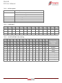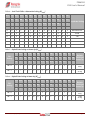
1
PE46120 Evaluation Kit (EVK) User’s Manual
Monolithic Phase & Amplitude Controller, 1.7–2.2 GHz
PE46120
Evaluation Kit
DOC-68985-1 – (08/2015)
EVK User’s Manual
www.psemi.com
PE46120
EVK User’s Manual
Copyright and Trademarks
©2015, Peregrine Semiconductor Corporation. All rights reserved. The Peregrine name, logo, UTSi and
UltraCMOS are registered trademarks and HaRP, MultiSwitch and DuNE are trademarks of Peregrine Semiconductor Corp.
Disclaimers
The information in this document is believed to be reliable. However, Peregrine assumes no liability for the use
of this information. Use shall be entirely at the user’s own risk. No patent rights or licenses to any circuits
described in this document are implied or granted to any third party. Peregrine’s products are not designed or
intended for use in devices or systems intended for surgical implant, or in other applications intended to support
or sustain life, or in any application in which the failure of the Peregrine product could create a situation in which
personal injury or death might occur. Peregrine assumes no liability for damages, including consequential or
incidental damages, arising out of the use of its products in such applications.
Patent Statement
Peregrine products are protected under one or more of the following U.S. patents: patents.psemi.com
Sales Contact
For additional information, contact Sales at [email protected].
Corporate Headquarters
9369 Carroll Park Drive, San Diego, CA, 92121
858-731-9400
Page ii
DOC-68985-1 – (08/2015)
www.psemi.com
PE46120
EVK User’s Manual
Table of Contents
Introduction - - - - - - - - - - - - - - - - - - - - - - - - - - - - - - - - - - - - - - - - - - - - - - - - - - - - - - 1
Introduction - - - - - - - - - - - - - - - - - - - - - - - - - - - - - - - - - - - - - - - - - - - - - - - - - - - - - - - - - - - - - - - - - - - - - - 1
Application Support . . . . . . . . . . . . . . . . . . . . . . . . . . . . . . . . . . . . . . . . . . . . . . . . . . . . . . . . . . . . . . . . . . . . . . . . . . . . . . . . . . 1
Evaluation Kit Contents and Requirements . . . . . . . . . . . . . . . . . . . . . . . . . . . . . . . . . . . . . . . . . . . . . . . . . . . . . . . . . . . . . 1
Kit Contents . . . . . . . . . . . . . . . . . . . . . . . . . . . . . . . . . . . . . . . . . . . . . . . . . . . . . . . . . . . . . . . . . . . . . . . . . . . . . . . . . . . . . . . . . . . . . . . . . . . . 1
Software Requirements . . . . . . . . . . . . . . . . . . . . . . . . . . . . . . . . . . . . . . . . . . . . . . . . . . . . . . . . . . . . . . . . . . . . . . . . . . . . . . . . . . . . . . . . . . 2
Hardware Requirements . . . . . . . . . . . . . . . . . . . . . . . . . . . . . . . . . . . . . . . . . . . . . . . . . . . . . . . . . . . . . . . . . . . . . . . . . . . . . . . . . . . . . . . . . 2
Evaluation Board Assembly - - - - - - - - - - - - - - - - - - - - - - - - - - - - - - - - - - - - - - - - - - 3
Evaluation Board Assembly Overview - - - - - - - - - - - - - - - - - - - - - - - - - - - - - - - - - - - - - - - - - - - - - - - - - - 3
Quick Start Guide - - - - - - - - - - - - - - - - - - - - - - - - - - - - - - - - - - - - - - - - - - - - - - - - - 5
Quick Start Overview - - - - - - - - - - - - - - - - - - - - - - - - - - - - - - - - - - - - - - - - - - - - - - - - - - - - - - - - - - - - - - - 5
Software Installation - - - - - - - - - - - - - - - - - - - - - - - - - - - - - - - - - - - - - - - - - - - - - - - - - - - - - - - - - - - - - - - 5
USB Driver . . . . . . . . . . . . . . . . . . . . . . . . . . . . . . . . . . . . . . . . . . . . . . . . . . . . . . . . . . . . . . . . . . . . . . . . . . . . . . . . . . . . . . . . . . . . 5
EVK Software . . . . . . . . . . . . . . . . . . . . . . . . . . . . . . . . . . . . . . . . . . . . . . . . . . . . . . . . . . . . . . . . . . . . . . . . . . . . . . . . . . . . . . . . . 5
Hardware Configuration - - - - - - - - - - - - - - - - - - - - - - - - - - - - - - - - - - - - - - - - - - - - - - - - - - - - - - - - - - - - 8
USB Interface Board Overview . . . . . . . . . . . . . . . . . . . . . . . . . . . . . . . . . . . . . . . . . . . . . . . . . . . . . . . . . . . . . . . . . . . . . . . . . 8
Evaluation Board Overview . . . . . . . . . . . . . . . . . . . . . . . . . . . . . . . . . . . . . . . . . . . . . . . . . . . . . . . . . . . . . . . . . . . . . . . . . . . . 9
Hardware Operation . . . . . . . . . . . . . . . . . . . . . . . . . . . . . . . . . . . . . . . . . . . . . . . . . . . . . . . . . . . . . . . . . . . . . . . . . . . . . . . . . 11
Using the Graphical User Interface - - - - - - - - - - - - - - - - - - - - - - - - - - - - - - - - - - - - - - - - - - - - - - - - - - - - 15
Continuous Pattern Loop . . . . . . . . . . . . . . . . . . . . . . . . . . . . . . . . . . . . . . . . . . . . . . . . . . . . . . . . . . . . . . . . . . . . . . . . . . . . . . . . . . . . . . . 16
Send Signal . . . . . . . . . . . . . . . . . . . . . . . . . . . . . . . . . . . . . . . . . . . . . . . . . . . . . . . . . . . . . . . . . . . . . . . . . . . . . . . . . . . . . . . . . . . . . . . . . . . . 16
Attenuation and Phase Slide Bar . . . . . . . . . . . . . . . . . . . . . . . . . . . . . . . . . . . . . . . . . . . . . . . . . . . . . . . . . . . . . . . . . . . . . . . . . . . . . . . . 17
Technical Resources - - - - - - - - - - - - - - - - - - - - - - - - - - - - - - - - - - - - - - - - - - - - - - - 19
Technical Resources - - - - - - - - - - - - - - - - - - - - - - - - - - - - - - - - - - - - - - - - - - - - - - - - - - - - - - - - - - - - - - - 19
Document Categories - - - - - - - - - - - - - - - - - - - - - - - - - - - - - - - - - - - - - - - - - - - - - 21
DOC-68985-1 – (08/2015)
Page iii
www.psemi.com
PE46120
EVK User’s Manual
This page intentionally left blank.
Page iv
DOC-68985-1 – (08/2015)
www.psemi.com
PE46120
EVK User’s Manual
Introduction
1
Introduction
The PE46120 is a HaRP™ technology-enhanced monolithic phase and amplitude controller (MPAC) designed
for precise phase and amplitude control of two independent RF paths. It optimizes system performance while
reducing manufacturing costs of transmitters that use symmetric or asymmetric power amplifier designs to
efficiently process signals with large peak-to-average ratios.
This monolithic RFIC integrates a 90° RF splitter, digital phase shifters and a digital step attenuator along with a
low voltage CMOS serial interface. It can cover a phase range of 87.2° in 2.8° steps and an attenuation range of
7.5 dB in 0.5 dB steps, while providing excellent phase and amplitude accuracy from 1.8–2.2 GHz.
The PE46120 also features exceptional linearity, high output port-to-port isolation and extremely low power
consumption relative to competing module solutions. It is offered in a 32-lead 6 × 6 mm QFN package.
The PE46120 evaluation kit (EVK) includes hardware required to control and evaluate the functionality of the
MPAC. The MPAC evaluation software can be downloaded at www.psemi.com and requires a PC running
Windows® operating system to control the USB interface board.
Application Support
For any technical inquiries regarding the evaluation kit or software, please visit applications support at
www.psemi.com (fastest response) or call (858) 731-9400.
Evaluation Kit Contents and Requirements
Kit Contents
The PE46120 EVK includes the following hardware required to evaluate the MPAC.
Table 1 • PE46120 Evaluation Kit Contents
Quality
Description
1
PE46120 MPAC evaluation board assembly (PRT-55151)
1
Peregrine USB interface board assembly (PRT-50866)
1
USB 2.0 Type A to Type B mini cable
DOC-68985-1 – (08/2015)
Page 1
www.psemi.com
PE46120
EVK User’s Manual
Software Requirements
The MPAC evaluation software will need to be installed on a computer with the following minimum requirements:
• PC compatible with Windows™ XP, Vista, 7 or 8
• Mouse or other pointing device
• USB port
• HTML browser with internet access
• Administrative privileges
Hardware Requirements
In order to evaluate the performance of the evaluation board, a Vector network analyzer is required.
Caution: The PE46120 MPAC EVK contains components that might be damaged by exposure to voltages in
excess of the specified voltage, including voltages produced by electrostatic discharges. Handle the board in
accordance with procedures for handling static-sensitive components. Avoid applying excessive voltages to the
power supply terminals or signal inputs or outputs.
Page 2
DOC-68985-1 – (08/2015)
www.psemi.com
PE46120
EVK User’s Manual
Evaluation Board Assembly
2
Evaluation Board Assembly Overview
The evaluation board (EVB) is assembled with a PE46120, several headers and SMA connectors, as shown in
Figure 1.
Figure 1 • PE46120 Evaluation Board Assembly
DOC-68985-1 – (08/2015)
Page 3
www.psemi.com
PE46120
EVK User’s Manual
This page intentionally left blank.
Page 4
DOC-68985-1 – (08/2015)
www.psemi.com
PE46120
EVK User’s Manual
Quick Start Guide
3
Quick Start Overview
The EVB was designed to ease customer evaluation
of the PE46120 MPAC. This chapter will guide the
user through the software installation, hardware
configuration and using the graphical user interface
(GUI).
Software Installation
computer. The USB interface and MPAC application
software is compatible with computers running
Windows®, XP, Vista, 7, 8, in 32- or 64-bit configurations. This software is available directly from
Peregrine’s website at www.psemi.com.
To install the MPAC evaluation software, unzip the
archive and execute the “setup.exe” (Figure 3).
Figure 3 • MPAC Evaluation Software Installer
USB Driver
The latest USB interface board drivers are available
via Microsoft Windows update. Internet connectivity is
required to download the drivers. Connect the USB
interface board to the PC and select the Windows
Update option to obtain and install the drivers
(Figure 2).
If the USB board drivers are not installed, it will not be
possible to complete the installation of the MPAC EVK
software. A USB interface board (Figure 11) is
included in the evaluation kit.
After the setup.exe file has been executed, a welcome
screen will appear. It is strongly recommended that all
programs be closed prior to running the install
program. Click the “Next>” button to proceed.
Figure 4 • MPAC Evaluation Software Setup
Figure 2 • USB Driver Installation (Detecting)
EVK Software
In order to evaluate the PE46120 performance, the
application software has to be installed on your
DOC-68985-1 – (08/2015)
Page 5
www.psemi.com
PE46120
EVK User’s Manual
Take a moment to read the license agreement, then
click “I Agree” and “Next>”
In the window of Confirm Installation, click “Next>” to
proceed with the software installation.
.
Figure 5 • License Agreement
Figure 7 • Confirm Installation
For most users the default install location for the
program files is sufficient. If a different location is
desired, the install program can be directed to place
the program files in an alternate location. The
software is installed for “Everyone” by default. Once
the desired location is selected click “Next>.”
As the software files are installed, a progress indicator
will be displayed. On slower computers, installation of
the software may proceed for a few moments.
Figure 8 • Progress Indicator
Figure 6 • Select Installer Folder
Page 6
DOC-68985-1 – (08/2015)
www.psemi.com
PE46120
EVK User’s Manual
Once the evaluation software is installed, click “Close”
to exit.
Figure 9 • Installation Complete
A new Start Menu item under Peregrine Semiconductor will appear in the start menu of your computer.
Select “MPAC Evaluation Software” to launch the
GUI.
Figure 10 • MPAC Evaluation Software Launch
DOC-68985-1 – (08/2015)
Page 7
www.psemi.com
PE46120
EVK User’s Manual
Hardware Configuration
USB Interface Board Overview
The USB interface board (Figure 11) is included in the evaluation kit. This board allows the user to send serial
peripheral interface (SPI) commands to the device under test by using a PC running the Windows® operating
system. To install the software, extract the zip file to a temporary directory and follow the installation procedure
included.
Figure 11 • USB Interface Board
Connection of the USB Interface Board to the Evaluation Board
The EVB and the USB interface board contain a 14 pin header. This feature allows the USB interface board
(socket) to connect directly to the EVB (pin) on the front side as show in Figure 12. Use caution when making
the connection to insure the USB interface board is aligned and connected to both rows of pins properly.
Figure 12 • USB Interface Board Connected to the Evaluation Board
Page 8
DOC-68985-1 – (08/2015)
www.psemi.com
PE46120
EVK User’s Manual
Evaluation Board Overview
The evaluation board is designed to ease customer evaluation of Peregrine’s products. The board contains:
1) Digital signal connectors are provided for power supply, digital control signals and USB interface board.
2) SMA connectors are provided for RF performance verification and THRU trace to calibrate board trace loss.
The schematic and evaluation board outline are provided in this user manual.
13
11
9
7
5
3
1
R11
C13
0 OHM
DNI
R10
C14
0 OHM
DNI
R9
C15
JP9
DNI
26
27
28
25
NC
NC
NC
NC
NC
31
29
30
RFOUT2
23
NC
NC
22
4
RFIN
DS
21
5
RFIN
6
NC
C10
C11
DNI
DNI
GND
19
7
SDO
RFOUT1
18
8
CLK
RFOUT1
17
1 MEGA
J11
J5
HEADER 2
SHORT
2 PIN JUMPER
JP5
J6
1
2
THRU
JP4
1
2
2 PIN JUMPER
GND
33
USB - RED
C4
0 OHM
DNI
DNI
R4
C5
1
2
1
2
DEVICE TEST FUNCTIONALITY
0.1uF
2
4
6
8
10
12
14
1
3
5
7
9
11
13
1
3
5
7
9
11
13
0 OHM
VDD_IFB1
HEADER 14
2
4
6
8
10
12
14
J1
JP1
C2
DNI
R5
C6
0 OHM
DNI
C7
DNI
JP2
J10
1 1
2 2
C8
JP3
J8
VDD
DNI
VDD
C1
100pF
R3
J7
50 Ohm
2 PIN JUMPER
50 Ohm
VDD_IFB1
50 Ohm
JP6
1
2
/SPEN 20
NC
R6
SDO
3
16
0 OHM
2
9
DNI
24
SDI
C3
1 1
2 2
RFOUT2
NC
R2
U1
PE46120
R1
DNI
OPEN
CLK
15
50 Ohm
50 Ohm
J2
1
NC
1 MEGA
NC
DNI
13
R7
LE
0 OHM
VDD
SDI 32
C16
J4
50 Ohm
JP7
DNI
R8
J3
JP8
1
2
VDD
0 OHM
12
0.1uF
11
100pF
1
2
DNI
LE
C18
10
C17
3 PIN JUMPER
DNI
HEADER 14
USB - RED
1
2
3
C12
NC
13
11
9
7
5
3
1
14
14
12
10
8
6
4
2
VDD
VDD_IFB2
J9
14
12
10
8
6
4
2
VDD_IFB2
Figure 13 • PE46120 Evaluation Board Schematic
100pF
C9
PIN
FUNCTIONALITY
12
TEST ENABLE 1
13
TEST OUT 1
19
POLARITY SELECT
28
TEST OUT 2
29
TEST ENABLE 2
HEADER 2
0.1uF
1
2
3
3 PIN JUMPER
INSTALL LOGIC JUMPERS ON
REF DES
NOTES:
1. CAUTION:
CONTAINS PARTS AND ASSEMBLIES SUSCEPTIBLE
TO DAMAGE BY ELECTROSTATIC DISCHARGE (ESD)
PINS
JP3
2-3
JP4
1-2
JP5
1-2
JP6
1-2
JP9
2-3
DOC-68985-1 – (08/2015)
Page 9
www.psemi.com
PE46120
EVK User’s Manual
Figure 14 • PE46120 Evaluation Board Outline Showing Functional Overview
USB Interface Board
Connector
VDD can be applied by
external power supply
VDD is applied from USB
board power supply
DS=0
RF Out 2
RF In
RF Out 1
VDD is applied from USB
board power supply
/SPEN=0
USB Interface Board
Connector
“THRU” trace is for board trace loss calibration
Page 10
DOC-68985-1 – (08/2015)
www.psemi.com
PE46120
EVK User’s Manual
Hardware Operation
The general guidelines for operating the hardware evaluation board are listed in this section. Follow the steps
below to configure the hardware properly for the performance.
1) Connect the jumper on JP4, JP5 and JP6.
a) JP4 is connected to PE46120 pin-19 (GND) to ground.
b) JP5 is connected to PE46120 pin-20 (/SPEN) to ground for normal SPI operation. Refer to datasheet
Table 11.
c) JP6 is connected to PE46120 pin-21 (DS) to ground as DS = 0 setting. Refer to Table 6 and Table 7.
2) There are two options to provide PE46120 a power supply. They are:
a) Option 1: Power up through USB interface board. Evaluation board is using this option by connecting
jumper on JP3 pin 2–3 and jumper on JP9 pin 2–3; refer to Figure 14.
b) Option 2: Power via external power supply. The evaluation board is configured for this option by installing
a jumper on JP3 pins 1–2 and JP9 pins 1–2 (refer to Figure 14). Connect the external power supply to
VDD_EXT J10 or J11 (pin 1+, pin 2–).
3) Plug in USB interface board (Figure 11) on J8 or J9, as shown in Figure 12. J8 and J9 provide identical control
to the device.
4) Calibrate board trace loss and phase with THRU trace between J6 and J7. THRU calibration is sufficient for
initial measurements. If more accurate results are desired, the full set of SLOT standards can be used.
Table 2 • Recommended Operating Condition for PE46120
Parameter
Min
Supply voltage, VDD(1)
Typ
2.3
Supply current
350
Max
Unit
5.5
V
500
µA
Digital input high
1.17
3.6
V
Digital input low
0
0.6
V
20
µA
RF input power, CW
29
dBm
RF input power, pulsed(2)
32
dBm
+105
°C
Digital input leakage
10
Operating temperature range
–40
+25
Notes:
1) Product performance does not vary over VDD.
2) Pulsed, 5% duty cycle of 4620 µs period.
DOC-68985-1 – (08/2015)
Page 11
www.psemi.com
PE46120
EVK User’s Manual
Table 3 • Bit Descriptions
C0
Channel register select
C0 = L, channel RFOUT1 register select
C0 = H, channel RFOUT2 register select
M0–M3
Attenuation setting per channel
P0–P4
Phase shift setting per channel
S0–S3
Spare bits
Table 4 • 14-bit Word
Q13
Q12
Q11
Q10
Q9
Q8
Q7
Q6
Q5
Q4
Q3
Q2
Q1
Q0
C0
S3
S2
M3
M2
M1
M0
P4
P3
P2
P1
P0
S1
S0
1
—
—
—
—
—
—
45
22.5
11.2
5.6
2.8
—
—
2
—
—
4
2
1
0.5
45
22.5
11.2
5.6
2.8
—
—
Table 5 • Serial Truth Table—Phase Setting
Q13 Q12 Q11
Q10
Q9
Q8
Q7
Q6
Q5
Q4
Q3
Q2
Q1
Q0
P3
P2
P1
P0
S1
S0
5.6
2.8
—
—
Phase Shift
Setting
C0
S3
S2
M3
M2
M1
M0
P4
1/2
—
—
4
2
1
0.5
45
X
X
X
X
X
X
X
L
L
L
L
L
X
X
Ref phase
X
X
X
X
X
X
X
L
L
L
L
H
X
X
2.8 deg
X
X
X
X
X
X
X
L
L
L
H
L
X
X
5.6 deg
X
X
X
X
X
X
X
L
L
H
L
L
X
X
11.25 deg
X
X
X
X
X
X
X
L
H
L
L
L
X
X
22.5 deg
X
X
X
X
X
X
X
H
L
L
L
L
X
X
45 deg
X
X
X
X
X
X
X
H
H
H
H
H
X
X
87.2 deg
22.5 11.2
Page 12
DOC-68985-1 – (08/2015)
www.psemi.com
PE46120
EVK User’s Manual
Table 6 • Serial Truth Table—Attenuation Setting (RFOUT2)
Q13 Q12
Q11
Q10
Q9
Q8
Q7
Q6
Q5
Q4
Q3
Q2
Q1
Q0
P3
P2
P1
P0
S1
S0
C0
S3
S2
M3
M2
M1
M0
P4
1
—
—
—
—
—
—
45
22.5 11.2
5.6
2.8
—
—
2
—
—
4
2
1
0.5
45
22.5 11.2
5.6
2.8
—
—
H
X
X
L
L
L
L
X
X
X
X
X
X
X
Ref insertion loss
H
X
X
L
L
L
H
X
X
X
X
X
X
X
0.5 dB
H
X
X
L
L
H
L
X
X
X
X
X
X
X
1 dB
H
X
X
L
H
L
L
X
X
X
X
X
X
X
2 dB
H
X
X
H
L
L
L
X
X
X
X
X
X
X
4 dB
H
X
X
H
H
H
H
X
X
X
X
X
X
X
7.5 dB
Amplitude Setting
Table 7 • Default State Settings at Power Up (RFOUT1)
Q13 Q12 Q11 Q10
DS
Setting
Q9
Q8
Q7
Q6
Q5
Q4
Q3
Q2
Q1
Q0
P3
P2
P1
P0
S1
S0
5.6
2.8
—
—
Default
Setting at
Power Up
C0
S3
S2
M3
M2
M1
M0
P4
1/2
—
—
4
2
1
0.5
45
DS = 0
—
—
—
—
—
—
—
L
L
L
L
L
—
—
0 dB
0 deg
DS = 1
—
—
—
—
—
—
—
H
L
L
L
L
—
—
0 dB
45 deg
22.5 11.2
Table 8 • Default State Setting at Power Up (RFOUT2)
Q13 Q12 Q11 Q10
DS
Setting
Q9
Q8
Q7
Q6
Q5
Q4
Q4
Q3
Q2
Q1
P3
P2
P1
P0
S1
S0
5.6
2.8
—
—
Default
Setting at
Power Up
C0
S3
S2
M3
M2
M1
M0
P4
1/2
—
—
4
2
1
0.5
45
DS = 0
—
—
—
L
L
L
L
L
L
L
L
L
—
—
0 dB
0 deg
DS = 1
—
—
—
H
H
H
H
H
L
L
L
L
—
—
7.5 dB
45 deg
DOC-68985-1 – (08/2015)
22.5 11.2
Page 13
www.psemi.com
PE46120
EVK User’s Manual
Table 9 • Serial Interface Timing Characteristics(1)
Parameter/Condition
Min
Max
Unit
Serial clock frequency, FCLK(2)
0.032
26
MHz
Serial clock period, TSCLK
40
ns
Serial clock HIGH time, TSCLKH
20
ns
Serial clock LOW time, TSCLKL
20
ns
Serial data output propagation delay from CLK falling edge, TOV (10 pF)
Latch clock pulse width high, TLCLKH
9
10
ns
ns
Serial data input setup time from CLK rising edge, TSU
5
ns
Serial data input hold time from CLK rising edge, TH
2
ns
Serial data output hold time from CLK rising edge, TOH
1.6
ns
Serial clock rising edge setup time to latch clock rising edge, TSETTLE
27
ns
SDO drive strength(3)
15
pF
Notes:
1) VDD = 2.3V–5.5V, –40 °C < TA < +1-5 °C, unless otherwise specified.
2) Limited by test duration not static logic design. Synchronous to clock. Minimum clock frequency tested = 32 kHz.
3) SDO maximum capacitive load drive strength for FCLK = MHz with a 1.8V swing.
Page 14
DOC-68985-1 – (08/2015)
www.psemi.com
PE46120
EVK User’s Manual
Using the Graphical User Interface
Figure 15 displays the MPAC application software graphical user interface (GUI), which has the USB interface
board plugged into the computer. The message “USB-SPI Interface Board #101-0653 connected” will indicate
that the USB interface board is connected and recognized. “Hardware Operation” as shown on page 11 is for the
EVK hardware configuration to use with the GUI control software. If the USB interface board is not connected
when the application software is launched, the message “No interface board connected! Please connect USBSPI Interface #101-0653” will appear at the bottom of the screen.
In the upper left corner, under the Peregrine logo, there is a drop-down menu item to select the part number for
evaluation and the part description is below the part number box.
The MPAC application software graphical user interface (GUI) is displayed in Figure 15 and illustrates the
available controls and messages available to the user.
Figure 15 • MPAC Application Software Graphical User Interface(*)
Note: * SDO in the serial interface waveform is read back from the MPAC to verify SDO toggling to indicate proper communication with the MPAC.
DOC-68985-1 – (08/2015)
Page 15
www.psemi.com
PE46120
EVK User’s Manual
Continuous Pattern Loop
Send Signal
The continuous pattern loop checkbox (see
Figure 16) allows the user to observe the evaluation
board automatically step through each of the phase
and attenuation states. Once the GUI reaches the
maximum state value the cycle begins again at the
minimum state value. This function can be started and
stopped at any time by selecting/deselecting the
checkbox.
The “Send Signal” box can be used to resend the
same data.
Figure 17 • Send Signal
Figure 16 • Continuous Pattern Loop
Page 16
DOC-68985-1 – (08/2015)
www.psemi.com
PE46120
EVK User’s Manual
Attenuation and Phase Slide Bar
The RF Out Path slide bar allows the user to quickly select the desired attenuation and phase. The arrows at the
left and right can be clicked to increase or decrease phase or attenuation state at the minimum step size. The
attenuation and phase value text box is updated with each change of the phase slider. This control is two-way;
the user can also enter a valid attenuation and phase value into this text box followed by the ENTER key to
program the hardware with the updated value.
Figure 18 • RFOUT1 Path Slide Bar
Figure 19 • RFOUT2 Path Slide Bar
DOC-68985-1 – (08/2015)
Page 17
www.psemi.com
PE46120
EVK User’s Manual
This page intentionally left blank.
Page 18
DOC-68985-1 – (08/2015)
www.psemi.com
PE46120
EVK User’s Manual
Technical Resources
4
Technical Resources
Additional technical resources are available for download in the Products section at www.psemi.com. These
include the Product Specification datasheet, S-parameters, zip file, evaluation kit schematic and bill of materials,
material declaration form and PC-compatible software file.
Trademarks are subject to trademark claims.
DOC-68985-1 – (08/2015)
Page 19
www.psemi.com
PE46120
EVK User’s Manual
This page intentionally left blank.
Page 20
DOC-68985-1 – (08/2015)
www.psemi.com
PE46120
EVK User’s Manual
Document Categories
Advance Information
The product is in a formative or design stage. The document contains design target specifications for product
development. Specifications and features may change in any manner without notice.
Preliminary Specification
The document contains preliminary data. Additional data may be added at a later date. Peregrine reserves the
right to change specifications at any time without notice in order to supply the best possible product.
Product Specification
The document contains final data. In the event Peregrine decides to change the specifications, Peregrine will
notify customers of the intended changes by issuing a CNF (Customer Notification Form).
Not Recommended for New Designs (NRND)
This product is in production but is not recommended for new designs.
End of Life (EOL)
This product is currently going through the EOL process. It has a specific last-time buy date.
Obsolete
This product is discontinued. Orders are no longer accepted for this product.
DOC-68985-1 – (08/2015)
Page 21
www.psemi.com