1
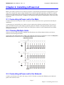
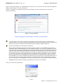
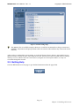
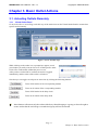
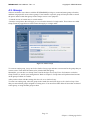
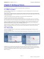
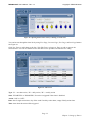
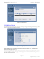
Rev 1.0 2009
ioPower.net User's Manual
ioPower.net
User's Manual
ioPower.net User's Manual Rev 1.0
Copyright © PROSUM 2009
Contents
CHAPTER 1. INTRODUCTION.................................................................................................................................... 4
1.1.
1.2.
MAIN FEATURES ................................................................................................................................................ 5
FRONT AND REAR PANELS ................................................................................................................................. 6
CHAPTER 2. INSTALLING IOPOWER.NET ............................................................................................................. 7
2.1.
2.2.
2.3.
2.4.
2.5.
CONNECTING IOPOWER.NET TO THE MAIN......................................................................................................... 7
CHAINING MULTIPLE UNITS .............................................................................................................................. 7
CONNECTING IOPOWER.NET TO THE NETWORK ................................................................................................. 7
CONFIGURING THE SYSTEM SETTINGS OF IOPOWER.NET.................................................................................... 9
GETTING HELP ................................................................................................................................................. 10
CHAPTER 3. BASIC OUTLET ACTIONS ................................................................................................................. 11
3.1.
3.2.
ACTUATING OUTLETS REMOTELY ................................................................................................................... 11
MONITORING THE OUTLET STATUS ................................................................................................................. 13
CHAPTER 4. MANAGING OUTLETS ....................................................................................................................... 14
4.1.
4.2.
4.3.
GLOBAL SETTINGS ........................................................................................................................................... 14
INDIVIDUAL SETTINGS ..................................................................................................................................... 15
GROUPS ........................................................................................................................................................... 16
CHAPTER 5. SETTING UP TIMERS ......................................................................................................................... 17
5.1.
5.2.
5.3.
WHAT IS A TIMER? ........................................................................................................................................... 17
TIMER LISTS .................................................................................................................................................... 17
EDITING TIMERS .............................................................................................................................................. 19
CHAPTER 6. MANAGING USERS ............................................................................................................................. 21
6.1.
6.2.
6.3.
GENERALITIES ................................................................................................................................................. 21
USER LOCAL DATABASE .................................................................................................................................. 22
USER REMOTE AUTHENTICATION .................................................................................................................... 23
CHAPTER 7. GETTING ALARM NOTIFICATION ................................................................................................ 25
7.1.
7.2.
7.3.
SELECT ALARMS .............................................................................................................................................. 25
EMAIL ALARMS ............................................................................................................................................... 26
SNMP TRAPS................................................................................................................................................... 26
CHAPTER 8. MAINTENANCE ................................................................................................................................... 28
8.1.
8.2.
8.3.
8.4.
UPGRADING THE SOFTWARE ............................................................................................................................ 28
UPGRADING THE SWITCH CARD FIRMWARE .................................................................................................... 28
SAVING AND RESTORING A CONFIGURATION ................................................................................................... 28
UPLOADING CERTIFICATES .............................................................................................................................. 29
APPENDICES................................................................................................................................................................. 30
A1. TROUBLESHOOTING ................................................................................................................................................ 30
A2. HARDWARE SPECIFICATIONS .................................................................................................................................. 31
A3. ORDERING INFORMATION ....................................................................................................................................... 32
A4. FCC / CE STATEMENTS .......................................................................................................................................... 32
List of Figures &Tables
ioPower.net User's Manual Rev 1.0
Copyright © PROSUM 2009
Figures
FIGURE 1: IOPOWER.NET, A REMOTE POWER CONTROL SOLUTION OVER IP ....................................................................... 4
FIGURE 2: SECURITY WARNING........................................................................................................................................... 8
FIGURE 3: LOGIN PROMPT ................................................................................................................................................... 8
FIGURE 4: MAIN MANAGEMENT PAGE ................................................................................................................................ 9
FIGURE 5: DATE AND TIME PAGE ........................................................................................................................................ 9
FIGURE 6: TCP/IP SETTINGS PAGE .................................................................................................................................... 10
FIGURE 7: POWER ON/OFF PAGE ..................................................................................................................................... 11
FIGURE 8: COLORED ICONS ............................................................................................................................................... 12
FIGURE 9: OUTLET STATUS MAP ....................................................................................................................................... 13
FIGURE 10: OUTLET GLOBAL SETTINGS ............................................................................................................................ 14
FIGURE 11: OUTLET INDIVIDUAL SETTINGS ...................................................................................................................... 15
FIGURE 12: OUTLET GROUPS ............................................................................................................................................. 16
FIGURE 13: OPENING AN OUTLET TIMER LIST ................................................................................................................... 17
FIGURE 14: OPENING A GROUP TIMER LIST....................................................................................................................... 17
FIGURE 15: OPENING OUTLET TIMER LIST BY CLICKING ON CLOCK ICON ........................................................................ 18
FIGURE 16: TIMER LIST ..................................................................................................................................................... 18
FIGURE 17: GROUP TIMER LIST ......................................................................................................................................... 19
FIGURE 18: EDITING A DAILY TIMER ................................................................................................................................. 19
FIGURE 19: EDITING A SINGLE-SHOT TIMER ..................................................................................................................... 20
FIGURE 20: USER LOCAL DATABASE................................................................................................................................. 22
FIGURE 21: USER EDIT ...................................................................................................................................................... 22
FIGURE 22: LDAP AUTHENTICATION SETTINGS ............................................................................................................... 23
FIGURE 23: ALARM SELECTION ......................................................................................................................................... 25
FIGURE 24: EMAIL ALARMS .............................................................................................................................................. 26
FIGURE 25: SNMP TRAPS ................................................................................................................................................. 27
FIGURE 26: SOFTWARE UPGRADE...................................................................................................................................... 28
List of Figures &Tables
ioPower.net User's Manual Rev 1.0
Copyright © PROSUM 2009
Chapter 1. Introduction
ioPower.net is a secure remote power management device using an IP SSL connection. It provides eight
outlets for any AC-powered device or computer and can be master of a daisy chain of several simple
ioPower units. When chained with seven ioPower companions, its management capacity can be increased to
64 outlets across a single IP SSL connection.
ioPower.net can be accessed across the LAN or the Internet by using any popular browser such as Internet
Explorer or Firefox. Its HTTPS web server provides multilevel menus for all management, monitoring, and
control operations. You can set up sophisticated timers or just toggle outlets with simple mouse clicks. A
Java® applet displays the state of all outlets under control in real time.
Figure 1: ioPower.net, a Remote Power Control Solution over IP
Page 4
Chapter 1. Introduction
ioPower.net User's Manual Rev 1.0
Copyright © PROSUM 2009
1.1. Main Features
1.1.1
•
•
•
•
•
•
1.1.2
•
•
•
•
•
•
•
•
•
•
•
•
•
Hardware
Full control of eight to 64 power outlets (when chained with seven ioPower units)
Numerical display to monitor the total current load (showing 0.0 ~ 15A)
LED indicators showing the state of outlets
Buttons for on/off control by front-panel
Circuit-breaker for over-current protection
19" rack-mountable design with metal case
Software
Web-based management using any standard browser on a remote computer
Power on/off by clicking on virtual buttons
One-time, daily of weekly timers for automatic actions
Individual naming of power outlets for easy management
User profiling
Outlet group configuration for group-wise power activation/deactivation
Precise system time using an internal RTC or synchronized by NTP servers
Can monitor sensitive computers by ping
SNMP and email alarms
Remote Flash upgrades via web
Password and/or LDAP user authentication
256-bit SSL encryption
1024-bit RSA authentication using certificates
Page 5
Chapter 1. Introduction
ioPower.net User's Manual Rev 1.0
Copyright © PROSUM 2009
1.2. Front and Rear Panels
1.2.1
Front-panel
Alarm LED: (Red)
Current Loads Display
Power Button
Bank Number Display
Power ON LED: (Green)
To actuate an outlet by using the front panel, press and hold the corresponding button for over two seconds.
The port is toggled upon button release.
1.2.2
Rear panel – for the US Region
POWER Reset button
Power Input
(IEC 320 C14)
110-240 VAC
Ethernet port
(RJ-45)
Power Output
(UL-498 5-15R)
Daisy-chain port (RJ-45)
- INPUT (unused)
- OUTPUT (lower)
1.2.3
Rear panel – for the EU Region
POWER Reset button
Power Input
(IEC 320 C14)
110-240 VAC
Ethernet Port
(RJ-45)
Power Output
(IEC 320 C13)
Daisy-chain port (RJ-45)
- INPUT (unused)
- OUTPUT (lower)
You might need to use extra adapter cords between ioPower.net and your devices, especially when the
devices are not of the plug specification that fits the standard power outlets on the back panel. These
adapter chords are not included with your package carton and are available by optional purchase.
Page 6
Chapter 1. Introduction
ioPower.net User's Manual Rev 1.0
Copyright © PROSUM 2009
Chapter 2. Installing ioPower.net
Before you connect your devices to ioPower.net, please verify that the specifications are appropriate for your
usage. For example, the output voltage should be in accordance with that required by your devices; and the
total power loads and the power loads per port should not exceed the maximum total (15A) and per port max
loads (6A) within its specification. In addition, the installation and operation should adhere to the local safety
regulations.
2.1. Connecting ioPower.net to the Main
Connect ioPower.net to the power outlet via its power chord, and ioPower.net is powered on and ready for
installation.
Connect those AC-powered devices, each to a power outlet on the ioPower.net back panel. You can try to
power ON/OFF any power outlet simply by pressing the power button on the physical front-panel of your
ioPower.net. Later, you will be able to name each of the power outlets for easier identification on the Web
Management Interface.
2.2. Chaining Multiple Units
ioPower.net can be daisy-chained to multiple non-IP ioPower units. When chained with seven ioPower,
ioPower.net can manage 64 outlets.
Use the daisy-chain cable (RJ45-RJ45, actually a UTP cable) that comes with your package to connect the DaisyChain
OUT Port (RJ45) of the ioPower.net to the DaisyChain IN Port (RJ45) of the first ioPower.
2.3. Connecting ioPower.net to the Network
Connect your ioPower.net to the LAN, using a CAT5 UTP cable to connect the Ethernet port on the back
panel to the network switch.
Page 7
Chapter 2. Installing ioPower.net
ioPower.net User's Manual Rev 1.0
Copyright © PROSUM 2009
From a networked computer, use a standard browser and try to access ioPower.net with its factory default IP
address and port: https://192.168.1.100:5000
At first, you might see a warning message about the authenticity of the certificate that is used on the
ioPower.net website.
Figure 2: Security Warning
Please just ignore it and choose “Continue to this website”
Users who need to prove their own ioPower.net identity on the network can buy a certificate from
Verisign, Thawte or any other official CA supported by their browser and then upload it to ioPower.net.
We do not provide any certificate other than those that are already resident in the unit.
It is the worth telling a few words about certificates.
Buying official certificates does not improve the security for this sort of embedded device. They just
cost money and have limited lifetime. You should better generate your own set of certificates by using
some free tool such as XCA for example. The security provided by certificates just depends on the trust
you place in the organism that delivered them. Normally you should trust you at least as much as any
official CA! Therefore, concerning applications involving only people belonging to the same company,
it is generally a good idea using a self-made set of certificates. Browser warnings are just here because
they try to prevent anyone accessing pirate web sites, which is not significant here. After your users
have installed your own root certificate into their browsers, they get no more warnings and the level of
security is the same as if using official certificates. You should not care that people having nothing to
do on your ioPower.net management web site get warnings. On the contrary, this is a factor of security.
PROSUM technical support can help you generating your own set of certificates.
Next, you will see the login Prompt:
Figure 3: Login Prompt
Page 8
Chapter 2. Installing ioPower.net
ioPower.net User's Manual Rev 1.0
Copyright © PROSUM 2009
At the login prompt, type in the default user name and password:
User name: superuser
Password: superu
Once logging in the web management interface, the main page opens:
Figure 4: Main Management Page
The Web Management Interface offers a multi-level menu for your easy navigation to every submenu and
page.
2.4. Configuring the System Settings of ioPower.net
Go to Main/Date & Time page to set up the system date and time. You can set the time zone by selecting the
Region and City where you have located the ioPower.net. You can set the date and the local time. You can
also find the option of “Synchronize with an Internet Time Server (NTP)”. Use the Internet timeserver option
and it will regularly be synchronized without human intervention. This is important for the precision of
timers.
After you have done the settings, remember to hit the Store Settings button before going to another page.
Figure 5: Date and Time Page
Go to Main/LAN TCP/IP page to set up the IP address and port number. Set the appropriate IP address and
port number and other network settings such as network mask, gateway, DNS, etc. for your ioPower.net.
Page 9
Chapter 2. Installing ioPower.net
ioPower.net User's Manual Rev 1.0
Copyright © PROSUM 2009
Figure 6: TCP/IP Settings Page
The DHCP is also an available IP option. However, we will not recommend it as long as a static IP is
available. A dynamic IP will pose problem to know its current value and thus may create some access
difficulty.
After you have completed the system setting, go to the Soft Restart/Restart Software page and hit Restart
Software button to restart the unit. After about 20 seconds, ioPower.net will be restarted with new settings.
Then try to access ioPower.net with a web browser, using the new IP and port number, to verify it is
accessible through the network.
2.5. Getting Help
Click the HELP button on each page to get detailed information about the page fields.
Page 10
Chapter 2. Installing ioPower.net
ioPower.net User's Manual Rev 1.0
Copyright © PROSUM 2009
Chapter 3. Basic Outlet Actions
3.1. Actuating Outlets Remotely
3.1.1
Virtual Outlet Panel
Go to Outlets/Direct Action Page, and click any of the outlet icons on the Virtual Outlet Panel to actuate that
specific outlet remotely.
Figure 7: Power ON/OFF Page
While clicking on the outlet icon, a prompt box appears to ask
you whether you really want to turn on or off that specific outlet.
Click OK to confirm and validate the power event.
After you have clicked OK to confirm, the outlet is toggled
immediately, and the status of the outlet is refreshed.
Note that you can toggle several ports at same time by clicking the following buttons:
Turns off all outlets of the corresponding module
Turns on all outlets of the corresponding module
Turns off all outlets in the daisy chain
Turns on all outlets in the daisy chain
These buttons will actuate only the outlets of the daisy chain belonging to a group you have the right to
access. Outlets that do not belong to an authorized group will not be actuated.
Page 11
Chapter 3. Basic Outlet Actions
ioPower.net User's Manual Rev 1.0
3.1.2
Copyright © PROSUM 2009
Colored Icons of the Virtual Outlet Panel
Figure 8: Colored Icons
Outlet Number
Timer status:
Orange: a timer is set
Blank: no timer set
Outlet Status
Yellow: ON
Blue: OFF
Grey: FORBIDDEN
Red: ALARM
You can get information about outlets and timers by flying over icons with the mouse cursor.
You can create of modify the timers bound to an outlet by clicking on the corresponding clock icon.
For example:
A blue outlet icon indicates that the outlet is OFF.
• You can get information about the outlet by flying over the icon with your mouse
cursor.
An orange clock indicates that at least one timer is set up for the outlet and a toggle is pending.
• You can get information about the pending action by flying over the clock with your
cursor.
• You can modify the timer by clicking on the clock.
A yellow outlet icon indicates that the outlet is ON.
The white clock means there is no timer set up and no automatic action is pending.
• You can put a timer on this outlet by clicking on the clock
A gray icon indicates that you are not authorized to perform ON/OFF action on this outlet.
For user and group management, please refer to Groups and Managing Users sections.
A red icon indicates that the outlet is malfunctioning.
The Power ON/OFF web page is refreshed each time you ask for an action or you click on the Refresh
button. Without manual action, the state of outlets and timers is not refreshed. Therefore, the state of
outlets may have change because a timer or another user has fired an action. Click on Refresh to make
sure that the icons reflect the current state of outlets.
On the contrary, the Status Map provides a real-time indication of outlet state. It is refreshed
automatically on a short time period basis. To open the Status Map box, please refer to section 3.2.
The Status Map box is the preferred monitoring tool, while the Power ON/OFF page is mostly
intended for actuating outlet relays, getting timer details, and setting up new timers.
Page 12
Chapter 3. Basic Outlet Actions
ioPower.net User's Manual Rev 1.0
Copyright © PROSUM 2009
3.2. Monitoring the Outlet Status
You can see the status of each outlet on either Front-Panel, Virtual Outlet Panel (WEB Management
Interface), and Status Map (WEB Management Interface).
3.2.1
Virtual Outlet Panel
The outlet status panel is only refreshed after user clicks on outlet icons or Refresh button.
3.2.2
Status Map
The Status Map is constantly refreshed in real time. It shows the real status of all modules connected
the daisy chain: outlet-state, pending timers and module current in amperes.
To evoke the Status Map, go to Outlets/ Status Map. You might be prompted with a login prompt again.
Enter your user name and password to gain access.
Figure 9: Outlet Status Map
Please note that the purpose of the Status Map is monitoring. You can leave it open in a corner of your
screen to survey the outlets in real time. Use the Virtual Outlet Panel if you need to toggle an outlet
manually.
Page 13
Chapter 3. Basic Outlet Actions
ioPower.net User's Manual Rev 1.0
Copyright © PROSUM 2009
Chapter 4. Managing Outlets
4.1. Global Settings
Click on Outlets/Global Settings. In this page, you can set up the parameters that will apply to ALL outlets
in the daisy chain.
Figure 10: Outlet Global Settings
Turn delay: delay added after each outlet switching when several outlets must be changed simultaneously.
This delay permits to limit the surge current when simultaneous changes are requested by a global or module
command, or by timers.
The outlets are always turned in same order from first outlet of ioPower.net to last outlet of last
ioPower module. If some devices have to be turned on in a certain order, just plug them accordingly to
reflect the imposed order.
Power Cycle Delay: Outlets powering computers can turn off and then turn on automatically if the ping test
fails. Indicate here the power off time during a power cycle.
Ping Start Delay: If the ping test is started too early, it may fail because the device or the computer is not
yet ready to respond. Indicate here the delay to postpone the ping test after the device is powered on.
Ping Period: Indicate here the approximate delay between two ping requests sent to the same device.
Page 14
Chapter 4. Managing Outlets
ioPower.net User's Manual Rev 1.0
Copyright © PROSUM 2009
4.2. Individual Settings
Click on Outlets/Individual Settings. In this page, you can change the settings of each outlet of each ioPower
module in the daisy chain on an individual basis.
Figure 11: Outlet Individual Settings
Outlet Name: The default outlet naming is PCmmoo, with mm standing for the module number in the daisy
chain, and oo standing for the module outlet number. Change this default name for a more self-speaking
name that will help you to remember the device connected to this outlet.
Ping Test: Check this box if you want to monitor a computer or an IP appliance connected to this outlet by
doing a periodic ping.
IP Address to Ping: Indicate the IP address or the host name of the appliance or computer to ping.
The ping address does not belong necessarily to the computer that is plugged to this outlet. The only
limitation if you ping something else is that ioPower.net will not be able to power down or power cycle
the computer automatically.
Action and Alarms when Ping Test Fails: Check everything you want ioPower.net to do when the ping test
fail.
To be actually implemented, the Computer Ping Alarm must be also enabled.
Power Down: self-explanatory
Power Cycle: Turn off, wait for Power Cycle Delay, turn on, wait for Ping Start Delay, and then restart the
periodic ping test.
Send an Email: The email content is build automatically and is not user configurable. Refer to Email
Alarms to set up the email sender, recipients and SMTP server.
Send an SMTP Trap: An SNMP trap containing the description of the failure is sent to the SNMP manager.
Refer to SNMP Traps to set up the managers and the community
Page 15
Chapter 4. Managing Outlets
ioPower.net User's Manual Rev 1.0
Copyright © PROSUM 2009
4.3. Groups
ioPower.net allows users that are with the SUPERADMIN privilege to create and name groups of outlets,
and then assign specific users to these groups. Users bound to a specific group will only be able to control
the power outlets within that group. Outlet Groups can serve two purposes:
- Limit the access of certain users to certain outlets
- Permit to set up timers that will apply to a set of outlets instead of a single outlet. These timers are called
Group Timers by opposition to Outlet Timers that apply to a single outlet.
Figure 12: Outlet Groups
To create an outlet group, just go to Outlets/Outlet Groups page and enter a new name for the group that you
want to create. Then check the outlets to be joined within that group.
Meanwhile, you can also set a Group Timer. Just hit the Open the Group Timer List button to evoke the
Group Timer List, and do your setting therein. Refer to Chapter 5. Group timers will perform timed actions
on the group of outlets as a whole.
After you have done with the settings, hit Store the (new) Outlet Group.
To remove an outlet group, select the group in the combo box and click Suppress this Outlet Group. Note
that you cannot delete groups assigned to existing users. You must first either delete all users that are bound
to this group, or assign another group to them.
Page 16
Chapter 4. Managing Outlets
ioPower.net User's Manual Rev 1.0
Copyright © PROSUM 2009
Chapter 5. Setting up Timers
The management of timers is one of the most powerful features of ioPower.net.
5.1. What is a timer?
A timer is simply a pending action, i.e., a pending power on or power off that will be executed at a given
time of a given date.
Timers can have a single shot action or a periodic action. Single shot timers take effect at programmed date
and time. Periodic timers are rearmed automatically. They can act once a day at a given time, or once a week
at a given day and time.
Timers can be disabled. Obviously, this feature is not useful except for periodic timers.
The number of timers that can be setup is almost unlimited.
It makes no problem if two timers have same action at same time on same outlet. If two or several timers
have contradictory actions on same outlet at same time, the action is cancelled and the outlet is not actuated.
ioPower.net includes a quartz based real time clock. In addition, it can be synchronized with NTP servers.
Therefore, the time system is very accurate. The outlets should be actuated with a one-second precision.
However if ioPower.net is very busy, a few second delay can be seen.
ioPower.net timers can apply to a single outlet or to an outlet group. We call the first category Outlet Timers
and the second category Group Timers. Except from their field of application, Outlet Timers and Group
Timers are exactly same.
5.2. Timer Lists
You can see all timers bound to an outlet from the Outlet Individual Settings page by clicking on Outlet
Timer List. See Figure 13.
You can see all timers bound to a Group from the Outlet Groups page by clicking Open the Group Timer List.
See Figure 14.
Figure 13: Opening an Outlet Timer List
Figure 14: Opening a Group Timer List
In addition, you can open the outlet and group timer lists from the Power ON/OFF page by clicking on the
clock icon standing below each outlet. When the clock icon is white (no timer), it opens the page permitting
to create a new outlet timer. When the clock is orange, it opens the corresponding timer list.
Refer to Figure 15.
Page 17
Chapter 5. Setting up Timers
ioPower.net User's Manual Rev 1.0
Copyright © PROSUM 2009
Figure 15: Opening Outlet Timer List by Clicking on Clock Icon
You can browse through the timer list by using First Page, Previous Page, Next Page, and Last Page buttons.
See Figure 16.
Click New Timer to add a timer to the list. Click Edit Timer or Suppress Timer to edit or suppress the
selected timer. You can also double click in the timer list to open the selected timer for editing.
Figure 16: Timer List
Type: "S" = one-time action, "D" = daily action, "W" = weekly action
State: "ENABLED" or "DISABLED"; No action is triggered if the timer is disabled.
Action: "ON" or "OFF"
Date: date if single-action timer, day of the week if weekly-action timer, empty if daily-action timer
Time: time when the action will be triggered
Page 18
Chapter 5. Setting up Timers
ioPower.net User's Manual Rev 1.0
Copyright © PROSUM 2009
Figure 17: Group Timer List
5.3. Editing Timers
Into Edit Timer page, select the state, action type, and the type of trigger. Depending on the timer type, fill in
the date and time information. Refer to Figure 18.
Figure 18: Editing a Daily Timer
Single-shot timers can be programmed by specifying the trigger date and time or by specifying a delay
running from now. Refer to Figure 19.
Note: Specifying a delay is just a facility. The timer information is calculated and stored in the date and time
format. Next time you open the timer page, it will be displayed in the date and time format, and you will see
the values calculated by ioPower.
Page 19
Chapter 5. Setting up Timers
ioPower.net User's Manual Rev 1.0
Copyright © PROSUM 2009
Please note that all timer dates and times refer to the local time depending on your Time Zone parameters,
which specify the offset with the GMT as well as the daylight saving dates and time changes. Be aware that,
despite ioPower takes care of country-specific daylight saving systems, it may happen that the information
stored into ioPower is outdated because countries use to change their daylight saving parameters quite often.
Figure 19: Editing a Single-Shot Timer
Page 20
Chapter 5. Setting up Timers
ioPower.net User's Manual Rev 1.0
Copyright © PROSUM 2009
Chapter 6. Managing Users
6.1. Generalities
ioPower.net allows three user types: SUPERADMIN, ADMIN and USER. SUPERADMIN has all rights.
ADMIN can access all outlets and has a lot or rights but cannot manage users and cannot do maintenance
operations. USER can handle outlets and timers provided they belong to his outlet group.
Refer to the table below for detailed list of Web Management rights:
Management Page
Main/Date & Time
Main/LAN TCP-IP
Main/Log
Outlets/Direct Action
Outlets/Global Settings
Outlets/Individual Settings
Outlet/Groups
Outlet/Map
Timer/List
Timer/Edit
Users/local database
Users/LDAP
Alarms/Emails
Alarms/SNMP
Alarms/Selection
Maintenance/Software Version
Maintenance/Software Upgrade
Maintenance/Config. Save/Restore
Maintenance/Load Certificates
Maintenance/Reboot
Soft Restart
SUPERADMIN
x
x
x
x
x
x
x
x
x
x
x
x
x
x
x
x
x
x
x
x
x
ADMIN
x
x
x
x
x
x
x
x
x
x
x
x
x
USER
x
x
x
-
Full Access
Group Access
No Access
Users can be managed locally or by using a remote LDAP server for centralized management. To manage
users locally, open the Users/Local Database page.
Page 21
Chapter 6. Managing Users
ioPower.net User's Manual Rev 1.0
Copyright © PROSUM 2009
6.2. User Local Database
In the Users/Local Database page, you can see the listing of existing user entries.
Figure 20: User Local Database
Each entry exhibits the user name, together with the user type, the outlet group constraining the user, and a
free description.
You can use First Page / Next Page / Previous Page /Last Page to navigate through the pages of the user
database listing.
To add, edit, or delete an entry, select a raw and click the corresponding button. You can also edit a user
entry by double clicking on the user raw.
Figure 21: User Edit
In the User Edit page, type the user name, the user description and the user password. Select the user type
from among SUPERADMIN, ADMIN, and USER. If the user type is USER, select the group of outlets he
will have the right to access. Do not forget to click Store User.
Page 22
Chapter 6. Managing Users
ioPower.net User's Manual Rev 1.0
Copyright © PROSUM 2009
6.3. User Remote Authentication
The User Remote Authentication feature permits ioPower.net to access directory servers - Active Directory
for example - in order to authenticate users trying to login. Transactions with the directory servers are based
on the Lightweight Directory Access Protocol (LDAP). This feature permits to integrate ioPower.net into
your global enterprise user management.
By default, the User Remote Authentication is disabled. In this case, the authentication is made in local by
using the Local User Database on ioPower.net.
Please note that the information from the local database has the precedence over the information
coming from the remote directory server. Therefore, if a user is at same time into the local database
and into the remote directory, the information from the local database is taken in priority.
When accessing the directory server, ioPower.net will check the user ID and password and will try to get the
"kusergroup" attribute of this user. The "kusergroup" attribute can be SUPERADMIN, ADMIN or the name
of the outlet group assigned to this user. If the directory server acknowledges the user but does not return the
"kusergroup" attribute, ioPower.net takes "USER" by default.
Please note that the schema of the directory must be extended to provide the "kusergroup" attribute in
return to ioPower.net authentication requests.
If you do not want to modify the schema of your directory, you can still use it for authenticating simple
users. In this case, into the local database of ioPower.net, the administrator(s) must be setup and the
"USER" outlet group must exist. All simple users will be authenticated by the directory server(s) and
will access the set of outlets specified into "USER".
To setup the connection to the directory servers, open Users/LDAP Auth and check LDAP Authentication.
Refer to Figure 22.
Figure 22: LDAP Authentication Settings
SSL Access: Check this option if you want to enable SSL access of the LDAP authentication
However, to use this option, you should make sure your directory server supports LDAP through SSL.
You must install a distinct certificate – ldapcert.crt– onto the ioPower.net by uploading it through the
Load Certificate page. Normally this certificate should be generated by the directory server itself.
Port: Enter here the port number used in LDAP authentication. By default, it is set to 389 if SSL is not used
and 636 if SSL is used.
LDAP Server: Enter here the IP address or host name of the directory server.
Page 23
Chapter 6. Managing Users
ioPower.net User's Manual Rev 1.0
Copyright © PROSUM 2009
Second Server (if any): If a second directory server is available for authentication, enter its IP address or
host name here.
User Base Search DN: Here you should enter the user base search DN, which is typical to the directory
server you use for authentication. Enter something such as: CN=users,DC=domain, DC=com
If you do not know, please ask to your directory server administrator.
Page 24
Chapter 6. Managing Users
ioPower.net User's Manual Rev 1.0
Copyright © PROSUM 2009
Chapter 7. Getting Alarm Notification
ioPower.net can send email alarms or send SNMP traps to notify administrators about any of the three
critical alarm-triggering events: Bank over current, Broken Relay, and Computer ping (no reply).
7.1. Select Alarms
ioPower.net is able to send emails or SNMP traps, or perform automatically a power down or a power
cycling when a Bank over Current, a Broken Relay, or a Ping Test Failure event is detected.
To select the events and actions, go to Alarms/Selection.
Figure 23: Alarm Selection
Note: This page is where you can select which action ioPower.net must do when it detects an event. This
page is NOT the place where you can specify how the action is to be implemented. To do so, refer to SNMP
Traps, Email Alarms, and Outlet Settings.
7.1.1
Bank over Current
The overall current for the module is higher than 15A.
If you want that ioPower.net responds to this event, check Enable Alarm, and specify what type(s) of action
you would like ioPower.net does, Power Down, Send an Email, and/or Send an SNMP trap.
7.1.2
Broken Relay
A relay cannot be actuated any longer.
If you want that ioPower.net responds to this event, check Enable Alarm, and specify what type(s) of action
you would like ioPower.net does, Send an Email, or Send an SNMP trap.
7.1.3
Ping Test Fail
The computer or appliance does not respond to pings.
If you want that ioPower.net responds to this event, check Enable Alarm. Specify for each outlet into the
Outlet Settings page, what type(s) of action you would like ioPower.net does, Power Down, Power Cycle,
Send an Email, or Send an SNMP trap.
Page 25
Chapter 7. Getting Alarm Notification
ioPower.net User's Manual Rev 1.0
Copyright © PROSUM 2009
7.2. Email Alarms
Go to the Alarm/Emails page to set up the email notification for alarm events.
Figure 24: Email Alarms
Email from: Sender email address used by ioPower.net for alarm emails, for example:
[email protected]. It must be accepted by the SMTP server. This email address can help identify
which ioPower.net is the sender.
Email to: e-mail address of addressee.
You can use commas for multiple recipients: [email protected], [email protected],
[email protected]
Copy to: e-mail address of addressees who should get a “carbon copy” of alarm emails.
SMTP Server: Enter the host name or IP address of the SMTP server (mail server) that will route the
ioPower.net email alarms to recipients.
7.3. SNMP Traps
To receive and understand ioPower.net traps, you must first install the ioPower.net proprietary MIB into
your SNMP manager. You can get it from the ioPower.net CDROM of from the PROSUM web site.
Then, go to the Alarms/SNMP page. Refer to Figure 25. Here you can set up the SNMP traps sent by
ioPower.net, provided you selected the SNMP traps into the Select Alarm page or the Outlet Individual
Settings page.
Primary Manager: Specify here the IP address of the primary SNMP manager on your network.
Secondary Manager: Specify here the IP address of the secondary SNMP manager on your network (if any).
SNMP Community: The SNMP manager and agents must belong to an SNMP community identified by its
name, which is a collection of hosts grouped together for administrative purposes. Specify here the name of
the SNMP community to which your SNMP management host and SNMP agent belong.
Page 26
Chapter 7. Getting Alarm Notification
ioPower.net User's Manual Rev 1.0
Copyright © PROSUM 2009
Figure 25: SNMP Traps
Page 27
Chapter 7. Getting Alarm Notification
ioPower.net User's Manual Rev 1.0
Copyright © PROSUM 2009
Chapter 8. Maintenance
8.1. Upgrading the Software
When you receive the upgrade file, first copy it to your computer. Then use the ioPower.net web
management to perform the update across your LAN or across the Internet.
Go to the Maintenance/Software upgrade page.
Figure 26: Software Upgrade
Browse to where the update file is located, select the file, and click Upload.
Note: The software upgrade file must have a name starting with "ismod" followed by the date, such as
ismod-yy-mm-dd (for example ismod-08-03-29).
Note: The upgrade file is of accumulative nature, which means that normally you only need to use the latest
upgrade file to keep your ioPower.net most up-to-date.
Depending on the upgrade file size and the bandwidth available across the network, the file upload time can
vary from 2 minutes to 20 minutes. When the upload process is complete, the ioPower.net will reboot by
itself. After the reboot is complete, it should be working right away.
8.2. Upgrading the Switch Card Firmware
ioPower.net is built with two cards, the switch card using a small microcontroller and the IP card using an
ARM microprocessor. The ismod-yy-mm-dd upgrade files may include an upgrade for the small controller of
the switch card. If this firmware is newer than the firmware currently installed on the switch card, the IP card
proceeds to a flash memory upgrade of the switch card. This firmware upgrade is fully automatic and takes
about 5 minutes, so be patient. The switch card upgrade activity is displayed into the LED's of the front panel
("OP", "OH", etc.). Note that there is no display of this activity into the web management.
8.3. Saving and Restoring a Configuration
ioPower.net allows you to save the current settings into a compressed file (.tzg), and later use this file to
restore your user-specific settings to an ioPower.net. You can also restore the unit to factory settings.
It is wise to backup your configuration after any change. It can also be used to set up several ioPower.net
with same or similar configuration.
To save the current configuration in a file, go to Maintenance / Config. Save/Restore page. Click Save
Current Settings. Choose the location for saving your configuration file (*.tgz), and click OK. The format of
the configuration file name is isconfig-yyyymmdd.tgz, with a timestamp in it.
Page 28
Chapter 8. Maintenance
ioPower.net User's Manual Rev 1.0
Copyright © PROSUM 2009
To restore the configuration from a file, hit the Browse button to browse to the location of the update file
(isconfig-yyyymmdd.tgz) and then click Restore Settings. You will be prompted for a reboot when the
upload process is complete. Reboot ioPower.net to validate the new configuration.
To restore the factory default configuration, click Restore Factory Settings and confirm. Please note that
your current settings will be lost.
8.4. Uploading Certificates
Default PKI certificates and keys for the SSL HTTPS and LDAP connections are provided by default. If an
encrypted session is already enough for your security requirements, you can just ignore this aspect of PKI
authentication.
The default certificates are not trusted by the standard browsers because they have not been generated by an
official Certificate Authority such as Verisign or Thawte. Therefore, you will get some warnings at
connection time. To suppress these warnings, configure your browsers so that they accept the default
certificate, or get an "official" certificate from a trusted root Certification Authority. You can also generate
your own self-signed set of certificates by using some CA software tool (We recommend XCA). These
custom certificates will still not be trusted by the browsers until you configure your browsers so that they
accept them.
The valid file names of the PEM encoded X.509 certificates and RSA 1024-bit keys to be uploaded to
ioPower.net should be exactly as below:
•
•
•
•
root.crt: public certificate of the root Certification Authority
server.crt: SSL web server certificate emitted by root
serverkey.pem: public key used to sign server.crt
ldapcert.crt: certificate provided by the LDAP server for SSL connection. It must contain the key.
Note that ldapcert.crt is not required if your LDAP connection is not based on SSL
First, you should get a set of certificates from your administrator. If your certificates files have different
names, change them to the valid names before uploading.
To upload the certificates and keys, click the Browse button to go to the location where your certificates
reside. Select a certificate or key file and then click Upload to store it into ioPower.net. After the uploading
is complete, you should see the prompt page for reboot. Note that you do not have to reboot after each
certificate or key. Just reboot once after you have uploaded all the necessary certificates and keys:
Page 29
Chapter 8. Maintenance
ioPower.net User's Manual Rev 1.0
Copyright © PROSUM 2009
Appendices
A1. Troubleshooting
You forgot the IP address and port number of ioPower.net
The simplest way is to use the IPBox software tool available on PROSUM web site.
You can also push Button #1 and Button #3 simultaneously for over 8 seconds until the current loads display
has changed to IP. The IP and port number is temporarily set to 192.168.1.100:5000. Please note that this
will NOT write to the configuration files.
A red LED is constantly flashing on one outlet
It indicates an outlet hardware failure. The corresponding outlet is mal functioning and cannot be toggled. In
normal conditions, the alarm LED should never be lit.
When you see a lit alarm LED, first disconnect the device connected to the outlet and then try to troubleshoot
by pressing several times the outlet button on the front-panel. If the alarm LED remains lit persistently, ask
for technical service from your local dealer.
Port Error (unable to power on)
Port Error (unable to power off)
The current loads red display is flashing
It means the total current loads exceed 15 AMP. Try to shutdown some devices to diminish the current loads.
ioPower.net cannot power on and no display or LED is lit
The circuit breaker might be open due to current overloads. Try to push the power reset button on the back
panel.
Resetting ioPower.net to factory default
Go to the Config Save page and hit the Restore to Factory Settings button.
Using Reboot
Reboot is a total device rebooting that can be used in case of trouble. Normally you never need to reboot
ioPower.net. Before trying Reboot, try Restart Software.
The switch card firmware is corrupted
If your firmware upgrade has not succeeded or your firmware is somehow corrupted and can no longer
function anymore, the current loads red display shows forth a message such as “OP”. Please try to upgrade
your firmware. If it fails, contact the technical support of your local dealer.
Page 30
Appendices
ioPower.net User's Manual Rev 1.0
Copyright © PROSUM 2009
A2. Hardware Specifications
Input Voltage
100 ~ 240 VAC @ 50~60 Hz
Output Voltage
100 ~ 240 VAC @ 50~60 Hz (Depending on power input)
AC Output
8 outlets
LED
8 Alarm (RED)
8 ON (Green)
2 Bank (Green / Numerical)
2 Current (Red / Numerical)
Connector Interfaces
8 Power Outlets :
US: UL-498 5-15R
EU: IEC 320 C13
1 Ethernet port (RJ-45)
2 Daisy-Chain port (RJ-45)
1 Power receptacle
Front-panel control
8 Power buttons (“One Touch” ON/OFF with delay)
WEB Management Interface
Multi-level Menu-driven setting and Operation / SSL encrypted
Daisy-chain level
Up to 8 units ( 1 x ioPower.net + 7 x ioPower)
Daisy-chain interface
RJ-45 (via UTP cable)
Daisy-chain distance
1m
Max. current loads per port
6 amp per port
Current Overload Protection
15 amp max.
Operating Temperature
0~45°C
Operating humidity
10~90% RH
Storage Temperature
-20 ~ 70°C
Storage Humidity
0~90% RH
Dimensions (L x W x H)
410 x 165 x 44.5 mm
Certification
FCC, CE, UL
Page 31
Appendices
ioPower.net User's Manual Rev 1.0
Copyright © PROSUM 2009
A3. Ordering Information
ioPower.net
8-port Remote Power Control over IP, Cascadable
ioPower
8-port RS232 Power Control, Cascadable
A4. FCC / CE Statements
FCC Statement: This equipment has been tested and found to comply with the regulations for a Class B
digital device, pursuant to Part 15 of the FCC Rules. These limits are designed to provide reasonable
protection against harmful interference when the equipment is operated in a commercial environment. This
equipment generates, uses, and can radiate radio frequency energy and, if not installed and used in
accordance with this User Guide, may cause harmful interference to radio communications. Operation of this
equipment in a residential area is likely to cause harmful interference in which case, the user will be required
to correct the interference at his/her own expense.
CE Statement: This is a Class B product in a domestic environment, this product may cause radio
interference, in which case the user may be required to take adequate measures.
RoHS Compliant
Page 32
Appendices