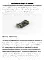
1
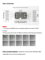
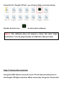
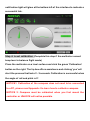
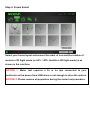
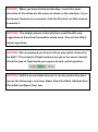
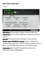
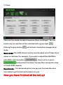
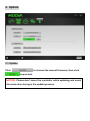
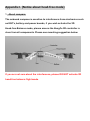
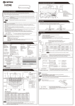
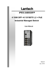
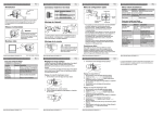
Contents
WARNING AND DISCLAIMER ....................................................................... 2
1. INTRODUCTION ....................................................................................... 3
Flight Mode ............................................................................................. 3
1 3D stable....................................................................................... 3
2 3D balance .................................................................................... 3
3 2D stable....................................................................................... 3
4 2D balance .................................................................................... 4
5 2D head-free balance .................................................................... 4
2. SETUP WIZARD ....................................................................................... 5
Step 1. connecting .................................................................................. 6
Step 2. install ssistant software .............................................................. 6
Step 3. connect the controller ................................................................. 7
Step 4. level calibration ......................................................................... 8
Step 5. frame select ................................................................................ 9
Step 6. transmitter calibration ............................................................... 10
Step 7. rates and PID gains. ................................................................... 12
7.1 rates........................................................................................... 12
7.2 gains .......................................................................................... 13
3. Update ................................................................................................... 14
3.1 update............................................................................................. 14
3.2 recovery mode ................................................................................ 15
4. LED Function ......................................................................................... 16
5. ARM and DISARM ................................................................................... 17
5.1 ARM ................................................................................................ 17
5.2 DISARM........................................................................................... 17
Appendix I. (Notice about head-free mode) ................................................. 18
User Manual for KungFu 3D controller
Thank you for purchasing this product from Moovatech. Before you start,
please read the manual carefully. The following steps will walk you
through the mounting and configuration of the KungFu 3D controller on
your multirotor and open up a world of 3D flight to explore.
Warning & Disclaimer
The KungFu 3D flight controller is specifically designed for multirotor 3D
flight, it is easy to use and the performance is superb. We have invested
a lot of time in to the design to ensure it is as safe as possible but it can
still be dangerous in 3D mode if not fully understood. We strongly
recommend customers REMOVE ALL PROPELLORS while installing it,
please carefully follow the steps in this manual to complete your setup
correctly and safely. Moova Tech assumes no liability for damages or
injuries incurred directly or indirectly from the use of this product.
1. Instructions
Flight Mode
1
3D
0% - 50% of the throttle range corresponds to reversed motor rotation,
50% - 100% range of the throttle corresponds to normal motor rotation,
in this mode the multirotor will not keep level balance automatically
while roll and pitch are centered. Also known as 'manual', 'acro' or 'rate
mode' but with added reversing of motors for inverted flight.
2
3D balance
0% - 50% of the throttle range corresponds to reversed motor rotation,
50% - 100% range of the throttle corresponds to normal rotation, in this
mode the multirotor will maintain level balance automatically while roll
and pitch are centered. This is often called 'horizon' or 'mix mode' but
with added reversing of motors for inverted flight.
3
2D
0% - 100% of the throttle range corresponds to normal motor rotation
only, in this mode the multirotor will not keep level balance automatically
while roll and pitch are centered. Also known as 'manual' , 'acro' or 'rate
mode', the multirotor will still flip and roll but is not capable of inverted
flight.
4
2D balance
0% - 100% of the throttle range corresponds to normal motor rotation
only, in this mode the multirotor will maintain level balance automatically
while roll and pitch are centered. The multirotor will still flip and roll and
the angle of tilt is not limited. This is often called 'horizon' or 'mix mode'
but is not capable of inverted flight.
(This mode can function as a rescue mode, if you are flying 3D and lose
orientation, switching to this mode will quickly roll the multirotor back to
normal flight and keep balance.)
5
2D head-free balance
0% - 100% of the throttle range corresponds to normal motor rotation
only, in this mode the multirotor will maintain level balance automatically
while roll and pitch are centered.
(This mode functions a rescue mode, if you are flying 3D and lose
orientation, switching to this mode will quickly roll the craft back to
normal flight and keep balance. Now pulling backwards on pitch will
return the quad to the initial take off point, the pilot is still in full control
of the throttle)
Notice: The compass is a sensitive magnetic sensor and the nature of
this means it is also sensitive to interference from other electronics
such as ESC and FPV equipment. Please make sure the compass works
fully before using this mode. For more details, please read Appendix I.
2. Setup Wizard
Please remove all propellers while you mount and configure the KungFu
3D flight controller.
Step 1. Connecting
Notice:
1. For S.bus and PPM receiver, plug the signal wire into the “AILE”
channel.
2.Please ensure the order of ESCs are identical with the pictures below.
Step 2. Assistant Software (Windows only at present although a Mac
compatible version will be available soon).
Unzip the file “KungFu 3D.zip”, you will get a folder as shown below.
Double click the icon
to start up the software.
Notice: The software does not require a driver like other flight
controllers, it is fully plug and play via USB with cable provided.
Step 3. Connect the controller
Using the USB cable to connect to your PC will also provide power to
the KungFu 3D flight controller. When connected, the green 'Connected'
notification light will glow at the bottom left of the interface to indicate a
successful link.
Step 4. Level calibration (Complete this step if the multirotor cannot
keep level in balance flight mode)
Place the multirotor on a level surface and click the green 'Calibration'
button on the right. The tip box offers assistance and clicking 'yes' will
start the process that lasts 2 - 3 seconds. Calibration is successful when
the angle of roll and pitch is 0°.
NOTICE1: Calibration of the compass does not need to be connected
to a PC, please read Appendix I to learn how to calibrate compass.
NOTICE 2: Compass must be calibrated when you first mount the
controller or UNLOCK will not be possible.
Step 5. Frame Select
Select your frame layout and ensure the order of esc and the rotation of
motors in 2D flight mode (or 50% -100% throttle in 3D flight mode) is as
shown in the interface.
NOTICE 1: Motor test requires a 3s or 4s lipo connected to your
multirotor as the power from USB alone is not enough to drive the motors.
NOTICE 2: Please remove all propellers during the motor test procedure.
Step 6. RC calibration
First:
Power on your transmitter and make sure the transmitter and receiver
are bound.
Second
Click 'Calibration' and follow the tip box, clicking 'YES' will automatically
identify your type of receiver. Now move all channels from minimum to
maximum range including all switches, sliders and rotary dials.
Last
Move throttle and rotary channel to middle place and click complete to
finish calibration.
NOTICE1: When you have finished calibration, check the input
direction of the sticks are the same as shown in the interface. If you
find some channels are reversed, click the 'Reverse' on that channel
to switch it.
NOTICE2: The display shown in the interface is left throttle only
regardless of the actual transmitter mode used. This will not affect
actual operation.
NOTICE3: We recommend you to use a three way switch channel to
be AUX1. This enables 3 flight modes to be set on the same channel.
Click the type of flight mode you require at each switch position.
NOTICE4: AUX3 is an assistant channel, it can be used to fine tune
one of the following in real time: Basic Gain Pitch/Roll, Attitude Gain
Pitch/Roll and Basic Gain Yaw
Step 7. Rates and PID Gains.
7.1 Rates
Max Attitude: The max angle of roll/pitch in balance flight mode.
Max Roll/Pitch: The max rate of roll/pitch at full range of the roll/pitch
channel.
Max Yaw: The max rate of yaw at full range of the yaw channel.
Throttle range of 3D ESC (For example): 1000us ~ 1450us for the
reversed throttle range,1450 ~ 1550 for the dead area on the middle of
the esc and 1550~2000 response for the normal throttle range.
OneShot125: When Onshot125 is enabled, the output will be
OneShot125 (2KHZ) or PWM (400HZ).
7.2 Gains
There are two modes to adjust response, Basic and Expert. You can
select only one and this will be indicated with a green light
Clicking the grey button
.
will activate it and allow changes to be
made.
Basic mode: The AUX3 channel can be used to adjust one of these three
values in real-time. For example, if you wish to adjust Rate Roll/Pitch
with AUX3, click the button
, then it will turn green
to show that it is active. You may then change the value
of it with AUX3 channel.
Expert mode:
For advanced pilots, here you can fine tune the value
accurately to get the best performance for you.
Now you have finished all the set up!
3. Update
3.1 Update
Click
to choose the newest firmware, then click
to proceed.
NOTICE: Please don’t move the controller while updating and avoid
disconnection during in the update process.
3.2 Recovery mode
If the update fails and the controller becomes unresponsive, use the
following method to resolve it.
Operation:
Step1
Connect AIL channel and PWM1(ESC1) output as below.
Step2
Connect the controller to your computer and start the Assistant
software. Go to the update page and click
the newest firmware and click
to choose
to update it.
Step3
After a successful firmware update, disconnect the KungFu 3D
controller from the computer and then disconnect the AIL channel and
ESC1 output.
Step4
Connect the controller to the computer with the original wiring and
repeat the update procedure.
4. Definition of LED
PW(Red LED):power indicator light.
ER (Red LED):error indicator light.
ST (Blue LED):state indicator light.
While the controller is powered on, the PW light will glow constant and
ST (blue led) will blink to shown that the controller is in self-inspection.
When the ST led is off, the controller is ready to unlock and fly.
Switch to ARM and the ST (blue led) will glow constant to show ARM is
successful. Now you can fly.
If ER (red led) light is on while ST light is off it indicates there are some
mistakes in the setup, please re-power the controller or connect it to
computer to see specifically what is wrong on the bottom left of the
interface.
NOTICE: Please do not move the multirotor after it is powered on
or the self-inspection of the controller may not initialize correctly.
The ST (blue led) must be off to allow ARM to be active.
5. ARM and DISARM
5.1 ARM
Power on your transmitter, put the ARM/DISARM switch on DISARM and
throttle to minimum.
Power on your multirotor and wait until ST (blue led) turns off.
Switch to ARM, the ST led will glow constant to show ARM is successful.
Now raise the throttle over 50% and the motors will start spinning, the
KungFu 3D is now ready to fly.
5.2 DISARM
Switching to DISARM will immediately cause the motors to stop running.
(DO NOT switch to DISARM while the multirotor is flying.).
NOTICE: To ensure your safety, DISARM will only activate when the
throttle is at minimum. The ST (blue led) will turn on to show
DISARM is active. If you switch to ARM and the ST does not turn on
constant, please check if the throttle is at minimum and try again.
Appendix I. (Notice about head-free mode)
1. About compass
The onboard compass is sensitive to interference from electronics such
as ESC's, battery and power boards, if you wish activate the 2D
Head-free Balance mode, please ensure the KungFu 3D controller is
clear from all components. Please see mounting suggestion below.
If you are not sure about the interference, please DO NOT activate 2D
head-free balance flight mode.
2.Compass calibration.
Step1
Power on your transmitter, then power on your multirotor and wait until
ST (blue led) turns off. Now move both sticks to the bottom left corner as
shown in the illustration below. ST (blue led) will blink quickly to show
Compass calibration mode is activated.
(Do not connect the controller to your computer)
Step2
Rotate your aircraft around the horizontal axis (about 360°) until the ST
(blue led) changes to flashing slowly before proceeding to step 3.
Step3
Hold your aircraft vertically and rotate it (the nose is pointing downward
towards the floor) around the vertical axis about 360° until the ST turns
constant blue. Proceed to step 4.
Step4
Place the multirotor on a level surface and wait until the ST turns off.
Calibration is now complete.