1
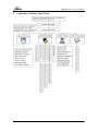
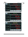
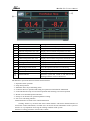
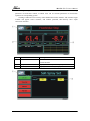
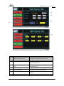
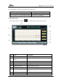
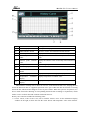
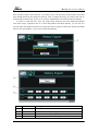
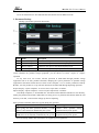
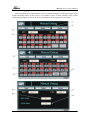
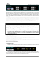
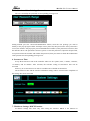
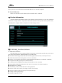
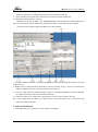
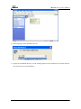
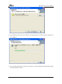
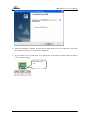
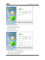
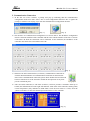
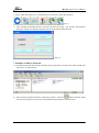
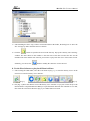
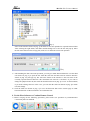
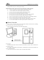
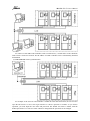
V:UMC1500.2.0.USER.E1.0 UMC1500 Series Salt Spray Test Chamber Program Controllers (V 2.0) User’s Manual ——Shanghai Becca Electronic Technological Co., Ltd.—— UMC1500(V2.0)User’s Manual Contents I. Controller’s Window Flow Chart……………………………………………………………… 2 II. Detailed Functions Introduction…………………………………………………………… 3 1. Initial Interface……………………………………………………………………………… 4 2. Salt spray Control……………………………………………………………………………… 4 3. Real-time curve………………………………………………………………………………9 4. History Curve…………………………………………………………………………………11 III. Advanced Operation……………………………………………………………………………13 1. Historical Dump………………………………………………………………………………14 2. Document Backup……………………………………………………………………………16 3. Manual Debugging……………………………………………………………………………17 4. Fault Record…………………………………………………………………………………19 IV. System Setting………………………………………………………………………………20 1. Time Setting…………………………………………………………………………………22 2. Pre-set Boot…………………………………………………………………………………22 3. Power Failure Recovery……………………………………………………………………23 4. Cumulative Run………………………………………………………………………………23 5. Modification of User Privilege Password……………………………………………………23 6. Screensaver Time………………………………………………………………………………24 7. IP Address Settings, DHCP Function………………………………………………………24 8. Touch Calibration…………………………………………………………………………24 Ⅴ. Product Information…………………………………………………………………………25 Ⅵ. UMC1500_User Host Software……………………………………………………………25 1. Software Functions…………………………………………………………………………25 2. Communication Settings………………………………………………………………………25 3. Software Installation…………………………………………………………………………26 4. Software Login……………………………………………………………………………30 5. Communication Connection……………………………………………………………………31 6. Use the Host Software to Export Files from the Controller……………………………………32 7. Examples of History Playback…………………………………………………………………32 8. Use the Host Software to Play back Historical Data……………………………………………33 9. Use the Host Software to Conduct Remote Control…………………………………………34 10. Description of File Types Involved in the Operation of Host Software………………………35 Ⅶ. Ethernet Connection………………………………………………………………………35 V:UMC1500.2.0.USER.E1.0 -1- UMC1500(V2.0)User’s Manual I. Controller’s Window Flow Chart V:UMC1500.2.0.USER.E1.0 -2- UMC1500(V2.0)User’s Manual Item Name Description ① Control interface Program control and fixed-value control selection ② Advanced operation Include advanced renewal/ history dump/document backup/manual debugging/ faults record/time limit setting ③ System setup Include system parameter setting, and inner parameter setting, etc. ④ Product information Display manufacturer information (can be set by the manufacturer itself) ⑤ Company model Manufacturer name and product model (can be set by the manufacturer itself) ⑥ Product version number Display version number ⑦ System time Display current system time name/product II. Function introduction 1. Initial Interface After being electrified for the first time and self examination of 15 seconds, the instrument will change from the initial interface to system function selection interface. 2. Salt spray Control V:UMC1500.2.0.USER.E1.0 -3- UMC1500(V2.0)User’s Manual V:UMC1500.2.0.USER.E1.0 -4- UMC1500(V2.0)User’s Manual Item Name Description ① Return button Return to the menu of previous step ② Cabinet temperature SV value Display current cabinet temperature set value ③ Saturator temperature SV value Display current saturator temperature set value ④ Operation status Display current fixed value operation status ⑤ System time Display current system time ⑥ Cabinet temperature PV value Display current cabinet temperature measured value ⑦ Saturator temperature PV value Display current cabinet temperature measured value ⑧ Salt-fog control status Display current salt-fog control switch status ⑨ Run time Display current run time ⑩ Self-tuning function button Go to the operation interface for self-tuning Self-tuning indication Display self-tuning status Reservation indicator Awaiting the system’s reservation to power on Alarm indicator When the system has a fault, it will alarm with a flashing indicator. Click to check more. Introduction to operation function of main control interface: 1)Operation: Start operation. 2)Stop: End operation 3)Maintain: Pause slope and timing status 4)Continue: Recover operation and timing for operations which shall be maintained. 5)Cancel: Related to setup of reservation operation and canceling reservation operation 6)Detail: Go to detailed operation interface. 7)Setup: Go to interface for operation parameter setting. 8)AT: Go to self tuning interface Detailed interface of fixed-value control information: Clicking “detail” key in fixed-value main control interface will lead to detailed interface of fixed-value control information, in which users can check relevant information of the system in detail. It is very helpful for observing the working condition of the system. Interface of setting parameter of fixed-value control: V:UMC1500.2.0.USER.E1.0 -5- UMC1500(V2.0)User’s Manual Clicking “setting” in fixed-value main control interface will lead to the interface of setting parameter of fixed-value control, in which users can set relevant parameters of fixed-value operation of corresponding system. Clicking A and B area successively in the detailed fixed-value interface. The customer login window will appear. Select customer, and confirm password, then directly enter “input correction” interface. Item Name Description ① Return button Click this button to return to fixed value main control interface ② Temperature OUT% Display current temperature output percent ③ Humidity OUT% Display current humidity output percent V:UMC1500.2.0.USER.E1.0 -6- UMC1500(V2.0)User’s Manual Item Name Description ① Cabinet temperature setup Set cabinet temperature target SV value ② Saturator temperature setup Set saturator temperature target SV value ③ Spray mode selection button Switch the spray mode between continuous mode and intermittent mode ④ Time setting for intermittent mode Set the operating time and stop time of intermittent mode ⑤ Time switch for fixed time Select to open or close fixed time operation ⑥ Fixed time setting Set the time for fixed time operation ⑦ Manual switch Manually control the spray, eject, open, close actions. ⑧ PID setting Set the PID values of the cabinet and the saturator V:UMC1500.2.0.USER.E1.0 -7- UMC1500(V2.0)User’s Manual Item Name Description ① Select cabinet temperature self-tuning Click it for cabinet temperature self tuning ② Cancel cabinet temperature self-tuning Click it to cancel cabinet temperature self tuning ③ Cabinet temperature self-tuning status Red means the cabinet temperature is self tuning, and black means the cabinet temperature is not self tuning. ④ Select saturator temperature self-tuning Click it for saturator self tuning ⑤ Cancel saturator temperature self-tuning Click it to cancel saturator temperature self tuning ⑥ Saturator temperature self-tuning status Red means the saturator temperature is self tuning, and black means the saturator temperature is not self tuning. Temperature self tuning interface: Click “AT” key in fixed-value main control interface to enter temperature self tuning interface Users are free to choose self tuning on or off. Self tuning can only be carried out in starting up status of fixed-value operation. After the start of self tuning, fixed-value operation will automatically enter maintaining status, and the upper right will show red “TAT’. After self tuning completes, the system will automatically end maintaining status and enter operation status. Relevant PID parameters after self tuning will be automatically recorded in the PID area of the system when self tuning starts. Self tuning function is mainly used in equipment adjustment stage. It is recommended that advanced users’ authority should be set on it after the completion, in order to avoid loss of PID parameters due to wrong operation. If you set users’ access privilege to “AT”, Click the button and a logging in window V:UMC1500.2.0.USER.E1.0 -8- UMC1500(V2.0)User’s Manual will pop up. You can have access to temperature self tuning interface only after choosing users’ grade meeting authority’s requirement and inputting right password. Operation status Reminding content Select self tuning in standby status “The system is not operated!” Click “continue” or “stop” during the tuning “The system is self tuning!” 3. Real-time Curve In the control interface, clicking icon will lead to real-time curve interface. Item Name Description ① Curve display area Real-time curve is displayed in this area ② Temperature display Display temperature coordinate value ③ Cabinet PV value Display current cabinet real measured value ④ Saturator PV value Display current saturator real measured value ⑤ Cabinet SV value Display cabinet set value ⑥ Saturator SV value Display saturator set value ⑦ Coordinate revision Click it to set temperature and humidity coordinates ⑧ Curve cleaning button Click it to clean real-time curve in the area and draw it again ⑨ History curve Click it to go to history curve interface ⑩ Humidity coordinate display Display humidity coordinate value V:UMC1500.2.0.USER.E1.0 coordinate -9- UMC1500(V2.0)User’s Manual The interface will meet users’ needs to browse the curve of real-time data. Continuous real-time record of the curve changes of the humidity in recent time will help users observe the changes of humidity, analyze the trend of the curve changes and find out the data change rule, so as to prevent accidents. In the curve display area, humidity PV curve will be shown in red line, cabinet temperature SV curve will be shown in blue line, saturator humidity PV curve will be shown in green line, saturator temperature SV curve will be show in dark yellow line. Real-time curve interface includes the following items: 1)Coordinate setup: Click the button and the coordinate setup dialog box will pop up. Change the size of curve display area by changing the length of coordinate axis, which will help users observe the curve well. In this window, users can set history curve’s maximum value “Y max” and minimum value “Ymin” of Y axis as well as the time length of X axis. The setup will be done after clicking “revision complete” button. The time setting range is 10~90 minutes. 2)Clean and redraw it: Clicking the button will clean the displayed curve in curve display area. The curve will be redrawn from current moment. 3)SV display: Clicking the button will shift display and concealing of humidity SV real-time curve in curve display area. ! Attention When you set, “Ymin” is not allowed to exceed “Ymax”. 4. History Curve In real-time curve interface, clicking icon will go to history curve interface. Clicking return key will return to real-time curve. V:UMC1500.2.0.USER.E1.0 - 10 - UMC1500(V2.0)User’s Manual Item Name Description ① Curve display area History curve displays in this area ② FWD and REV button Click it to realize forward and backward function ③ Current point time Display the time of currently chosen historical point ④ Current value cabinet Display the cabinet value of currently chosen historical point ⑤ Current point saturator value Display the saturator value of currently chosen historical point ⑥ Print preview button Click it to go to print window ⑦ Curve inquiry button Click it to set the start time of historical data ⑧ Coordinate button Click it to set coordinate and time of humidity ⑨ Used storage space Display currently used storage space proportion ⑩ Temperature display coordinate Display temperature coordinate value Humidity display coordinate Display humidity coordinate value point revision This interface can help users to have an overview of the historical data curve, helping them to check the historical data of equipment operation in the past. UMC1500 has the function of storing historical data, which will not disappear in case of power failure. When the system is in operation, it is able to make trend effect drawing of corresponding historical data according to requirements, which makes it easier to check data and variation trend status later on. History curve interface includes the following items: 1)Cursor: Cursor, a line in curve area, moves with the mouse’s move. In the information display window on the right, it shows the time the cursor directs and temperature value at the moment. V:UMC1500.2.0.USER.E1.0 - 11 - UMC1500(V2.0)User’s Manual 2)Operation button: Operation button includes basic operation of historical trend curve. <<<:One page up >>>:One page down <<:One main line time up, curve display up by a small margin >>:One main line time down, curve display down by a small margin 3)Curve inquiry: Click the button and curve inquiry dialog box will pop up. As shown in the image, while setting curve inquiry, users can input the start time of the data to be observed according to your needs. You can choose from the following items: 1)Saved data in recent X hours: by setting the time length, you can get the curve in recent certain period, usually one hour. 2)Set start time: Save the data at set time by setting start time of X axis. Users can skip to required time by using this option. The set time should not be later than current time. Note: if the start time is set too early, the controller’s speed may be affected because too much historical data many lead to long data loading time. So if users need to inquire historical data and curve in earlier period, it is suggested that you use UMC1000(User)upper software to operate. 3)Coordinate setting: Click the button and coordinate setting dialog box will pop up. Changing the size of curve display area by changing the length of coordinate axis will help users observe the curve well. In this window, users can set maximum “Ymax” and minimum “Ymin’ of Y axis of History curve as well as time length of X axis. The setting will be completed after pressing “revision complete” button. The time setting range is 1~10 hours, and “Ymin” cannot be larger than “Ymax”. 4)Clicking “print preview’ button of History curve interface will lead to printing interface V:UMC1500.2.0.USER.E1.0 - 12 - UMC1500(V2.0)User’s Manual Item Name Description ① Return (invisible key) Press this area to return to History curve interface ② Print (invisible key) Press this area to print the curve ③ Print information Display curve print information ④ Operator Input operator name ⑤ Remarks Input relevant remark information III. Advanced After clicking advanced operation button in function selection interface, you will enter advanced operation function selection interface. Advanced operation includes advanced renewal, historical dump, document backup, manual debugging and fault record. Item Name Description ① Historical dump Dump historical data of required temperature ② Manual debugging Manually debug input and output signals and analog output signals ③ Document backup Make a document backup copy of interior parameters and process connection setup of the system ④ Fault record Record of historical faults ⑤ Advanced renewal Insert a U disk with renewed document. Click this key to go to advanced renewal interface. Restart the system after confirmation and the system will enter renewed version. 1. Historical Dump In order to help users to dump the historical data of the humidity in required time scope, - 13 - V:UMC1500.2.0.USER.E1.0 UMC1500(V2.0)User’s Manual UMC1500 system collocates a historical data storage function with the longest time of 600 days(24 hours operation status/ record interval : one minute). Users can check the historical data of last 600 days through historical data playback function. After exceeding 600 days, the earliest data will be automatically cleaned by the system, so as to always maintain the recent historical data of 600 days. In order to avoid data loss, users can dump earlier historical data from UMC1500 through removable storage equipment such as U disk and portable hard disk. Besides, you can also use relevant upper data playback software to transfer the data to general use data-base format (ACCESS) and save it to the computer, so as to store the data permanently. Item Name Description ① Export button Confirm the start of historical data export ② Start time Set the start time of exporting historical data ③ End time Set the end time of exporting historical data ④ USB status Display the USB device connecting status of current system V:UMC1500.2.0.USER.E1.0 - 14 - UMC1500(V2.0)User’s Manual After entering historical dump interface, if the system can identify the portable storage equipment, the setting area of start time and end time will automatically show. After setting the start time and end time of historical data in required time scope, the system will automatically enter historical data dump process as long as you click “export” key. During the dump process, a progress bar will appear in the interface to display the dump progress. After the data dump completes, an information box will pop up to remind you “export complete!” A new file named by the exported time will be added to the root directory of the USB device, and it includes the historical data document with the postfix name of *.h12. ! Attention As the historical data documents of the system increases, the data dump time will become relatively longer. A progress bar will display current dump progress after the start of dump process. Please be patient waiting until the relevant information box pops up. Dump start/end time setting scope: Year Month Day Hour Minute 2000~2035 1~12 1~31 0~23 0~59 Other possible reminders which may appear during the operation: Operation status Reminding content After going into historical dump interface, if the USB device is not inserted or identified by the system Please insert portable storage equipment and operate again! Choose to click export operation while the USB device is not inserted or identified by the system Please insert portable storage equipment and operate again! End time is later than system time End time is later than current system time! End time is earlier than start time Start time cannot be later than end time! Export operation fails Invalid target path! Document cannot be created in target path(an operation which is only executed without USB device/read-only) No historical data document! Something wrong with creating document in target path! No data document suitable for the time scope(no data in the start and end time scope) Historical data of USB dump cannot be opened in upper computer. You need to use UMC1000_User software to transform the format and playback. After transformation, the document V:UMC1500.2.0.USER.E1.0 - 15 - UMC1500(V2.0)User’s Manual format will be changed to *.his12. Users can transform it to ACCESS data-base document based on different needs. 2. Document Backup Backup system inner parameter documents. Item Name Description ① Parameter import Confirm to start parameter document import process ② Parameter export Confirm to start parameter document export process ③ Process import Confirm to start process document import process ④ Process export Confirm to start process export process Document backup can help users to backup and dump useful parameter documents. After the system identifies the portable storage equipment, you can choose to execute “export’ or “import” operation. At any time users can execute relevant operation to UMC1500 through portable storage equipment such as U disk, portable hard disk, dumping the system parameters to portable storage equipment in document format and save them to the computer, so as to realize parameters backup. Besides, it is also possible to set up relevant documents in UMC1500 through importing operation. Export: display “export completes” on success and “export fails” on failure. Import: display “import completes” on success and “import fails” on failure. After dump completes, a“Paramdata.d12”document will be added to USB device root directory, namely the parameter document. When there are many process or parameter documents under the root directory of U disk, a selection list will pop up before importing. Other possible reminders which may appear during the operation: Operation status Reminding content After going into data operation interface, if USB device is not inserted or identified by the system “Please insert portable storage equipment and operate again!” Choose to click export or import operation while the USB device is not inserted or identified by the system “Please insert portable storage equipment and operate again!” Process backup: UMC1500 version does not support process operations. V:UMC1500.2.0.USER.E1.0 - 16 - UMC1500(V2.0)User’s Manual 3. Manual Debugging While debugging the equipment before using it, manually debugging switch output signals, input signals and analog output of the system is very helpful for users to know whether current system output and input signals are correct or the power distribution of the equipment is reasonable. V:UMC1500.2.0.USER.E1.0 - 17 - UMC1500(V2.0)User’s Manual Item Name Description ① Switch output Click it to enter switch output debugging status ② Switch input Click it to enter switch input debugging status ③ Input indicator 16 input indicators, green means input satisfaction ④ Analog output Click it to enter analog output debugging status ⑤ Locked/ unlocked Click it to lock/unlock ⑥ Button pages While using extension DCU selection, click it for DCU switching ⑦ ON key Force current point output ⑧ OFF key Force current point to turn off ⑨ Cabinet temperature Current cabinet temperate PV value ⑩ Temperature output% Manually set cabinet temperature output power, 0~100% Current humidity Current saturator temperature PV value for turning After choosing to click “manual debugging”, you will enter manual input operation interface, in which you can debug input signal manually or choose “switch output part” and “analog output part” to shift to switch output signal manual debugging interface or analog output signal manual debugging interface. Besides switch status display, in manual debugging interface there is also current temperature display of the system, which will help users to know more about current system’s condition. 1)Input signals: Use status bar reflects corresponding status of current switch input signals. When there is no signal input, the signal indicator is red, and when there is signal input, the indicator is green. 2)Output signals: In order to avoid wrong operation, “lock” and “unlock” function keys (the system default as locked) are added in manual output interface and manual output operation can be executed only in “unlocked” status. ON/OFF operations correspond with their output signal switches, ON means to force current point to export, and OFF means to force current point to turn off. The applied value reflects corresponding status of current switch input signals. No point output is shown as red and point output value is displayed as green 1. 3)Analog output signals: Users can set corresponding output percent in temperature output percent, and manually debug the heater. For example, set it to be 30%, heater’s power 1000W, and then the output will be 300W. ! Attention Wrong operation may hurt users or damage stuff. In manual debugging interface 101~I16 corresponds with DCU1000 module’s input point101~ I16, U01~I16 corresponds with DCU1000 module’s input point U01~U16. Temperature output percentage corresponds with ACU1000 module’s OUT1 output status, humidity output percentage corresponds with ACU1000 module’s OUT2 output status. 4. Fault Record Click “fault record’ key in advanced operation interface and the system will enter historical alarm record interface, in which users can check recent fault matters. Pressing clear key can clear all fault V:UMC1500.2.0.USER.E1.0 - 18 - UMC1500(V2.0)User’s Manual records. Displayed fault information includes the following content: Happening time: the happening time of the alarm accident; Releasing time: the releasing time of the alarm accident; Fault accident: fault name generating alarm Fault act: the fault means that the alarm happens/ releasing means that alarm ends Clearing operation of historical alarm record: Click clear key and return from historical alarm record interface, and the records will be cleared ! Attention Historical alarm window can only record 16 faults of fault setup of corresponding interior window, including module communication fault and temperature sensor disconnection fault. Ⅳ System Setting Click the System Setting button on the function selection interface to enter the System Setting function selection interface. System settings include nine sections: system time, pre-set boot, power failure recovery, remote operation, cumulative run time, password change, Screensavers time, IP address (DHCP) and touch calibration. Note: After setting the parameters in the input boxes, you need to exit the interface to activate all set parameters. V:UMC1500.2.0.USER.E1.0 - 19 - UMC1500(V2.0)User’s Manual Item Name Description ① System Time Set up the current system time ② Pre-set Boot Set up the pre-set boot status and corresponding time V:UMC1500.2.0.USER.E1.0 - 20 - UMC1500(V2.0)User’s Manual ③ Power Failure Recovery Select Reset/Cold Boot/Warm Boot ④ Page Up/Down Switch to system setting 2 ⑤ Cumulative Run Calculation of the total time from the initial use to the current working time ⑥ Password Modification Modify the password as per the user's requirement ⑦ Next Enter system setting 3 through the user logon window ⑧ Remote Control Select remote or local control ⑨ DHCP Automatically obtain IP address ⑩ Screensaver Time Select settings of screensaver time IP Address Set up the IP address Touch Calibration Select calibration to calibrate the screen DHCP Function Tips: This is the function to automatically obtain IP address and should not be used without connection between the controller and the router. If the controller is not connected with a router, please do not use this function and please manually allocate the IP address. 1. Time Setting This function can amend the current system time. Setting items: year, month, day, hour, minute, second, click “Enter” to finish the amendment. All historical data will be deleted after successful amendment of the system time. Scope of system time setting: Year Month Day Hour Minute Second 2000~2030 1~12 1~31 0~23 0~59 0~59 ! Attention: All historical data will be deleted if you modify the system time. 2. Pre-set Boot Set the system's pre-set boot status and corresponding pre-set time. When the system time arrives the set time, the system will automatically run. V:UMC1500.2.0.USER.E1.0 - 21 - UMC1500(V2.0)User’s Manual Press the corresponding icon to select the system pre-set boot status. The current status is indicated by the lit icon. When selecting the “Manual Boot”, the corresponding words of “Year, Month, Day, Hour, and Minute” will become pale and the pre-set time cannot be set up. When selecting the “Pre-set Boot”, the corresponding words of “Year, Month, Day, Hour, and Minute” will become white and the “Year, Month, Day, Hour, and Minute” can be set up. The setting scope is the same with the system time. After the pre-set boot is selected, there will be the flashing indication of “Timed Run” in the main control interface and detailed information interface, the main program control interface and their respective interfaces of detailed information, with the “Cancel” button appearing below. You can press the button to cancel the current pre-set boot setting and switch back to the manual boot mode. ! Attention During the switch of the system setting interfaces, if the current system time exceeds the pre-set run time, an information prompt box showing “Start time earlier than the current system time” will pop up, which cannot leave the current window. The self-tuning function has no power failure memory, so the system needs to be rebooted manually. Users are advised not to power off the running system. Because during the running of the system, saving historical data is to perform write operation of FLASH, power failure may damage the system. It is strongly recommended to stop the running system before power off. 3. Power Failure Recovery Cold boot: If rebooted after power failure under the operating status, the system indicates “maintained” and the operation can be continued. Warm boot: if rebooted after power failure under the operating status, operation will continue from the current minute before power off. Reset: system is in selection interface. 4. Cumulative Run Summing up the working time from the initial use time to the current time for users to check the equipment's status for corresponding maintenance and repair Indicating the total time from the first run to the end of the current run (excluding system standby time), including hour and minute (99999 hours 59 minutes at maximum) Click “Time Reset” and confirm the cumulative run time will be reset to 00000 hour 00 minute. V:UMC1500.2.0.USER.E1.0 - 22 - UMC1500(V2.0)User’s Manual 5. Modification of User Privilege Password The user can modify the password of corresponding privilege level. Setting method: press the “Password Modification” button, select the user privilege you want to modify in the pop-up login window and input correct password, then press Enter. If the password is correct, the interface will pop up the password modification window (if the password is incorrect, then the interface shows “the password is incorrect, please re-enter the password”). Input the old password, new password into the window and confirm the password, then press Enter to finish the modification of the password of corresponding privilege level. 6. Screensaver Time Set up the Screensaver time of the controller. There are five options, none, 1 minute, 5 minutes, 15 minutes, and 30 minutes. After selection, the real-time setting of Screensaver time will be activated. Please try to use Screensavers in order to extend the life of backlit LCD interface. The Screensaver time and the interface calibration settings will be activated after completion of the settings. No reboot is needed. 7. IP Address Settings, DHCP Function IP address settings take effect only after exiting the interface. DHCP is the function to V:UMC1500.2.0.USER.E1.0 - 23 - UMC1500(V2.0)User’s Manual automatically obtain IP address and must be used only when the controller is connected with the router. If not, please do not use this function and the IP addresses are manually assigned. 8. Touch Calibration When the controller's touch is deflected, the controller can be calibrated. Ⅴ. Product Information Click the Product Information button in the function selection interface to enter the production information viewing interface. The product information shown includes product model, product name, company name, company address, telephone, fax and company website. Ⅵ. UMC1000_User Host Software 1. Software Functions: The UMC1000_User user specific software can connect to UMC1500 controller to provide direct users for operation and use. Main functions are specified below: ◆ Real-time monitoring (monitor the real-time data, signal location status, actual output status) ◆ Watch list (monitor the running status of 1 to 16 controllers) ◆ History curve playback (play back the downloaded historical data curves within the controller) ◆ Program edit (edit program process and connection) ◆ Communication configuration (configure the IP address of the controller) ◆ FTP upload and download (historical data, process connection file, advanced updates) ◆ Real-time curve, printing ◆ Fault history view (view the fault state of the equipment) ◆ Remote fixed-value control (all settings of fixed-value running) ◆ Remote program control (all settings of program running) ◆ Setting of user logon privilege ◆ Multiple language selection V:UMC1500.2.0.USER.E1.0 - 24 - UMC1500(V2.0)User’s Manual 2. Communication Settings Steps to realize direct communications between the controller and the PC: 1)Check whether the network cable connection between the controller and the PC. 2)Manually set the IP address of the PC: Manually set the PC IP address for WINDOWS2000 or XP operation to 200.200.200.200. If there are several NICs, please check before setting which NIC is connected with the controller. The interface for manual setting of IP addresses is shown below: 1)Enter the attributes window of Network Neighborhood and select the attributes interface of “Local Connection” (1). 2)Double click (2) Internet Protocol (TCP/IP) to enter the interface of Fig. 3, select “Use the below IP address” and then click (4) “Advanced” button to enter Fig. (5). 3)Click (6) “Add” button to enter the interface of Fig. (7), modify the IP address to 200.200.200.200. Its subnet mask must be the same with that of the NIC. 4)After the setting, press “Add” button, then always press the “Enter” button to the end. Note: after setting of the IP address, you don’t need to reset the IP address for re-connection of the same PC with the controller. 3. Software Installation 1)Run UMC1000_User_Install.exe to start software installation. V:UMC1500.2.0.USER.E1.0 - 25 - UMC1500(V2.0)User’s Manual 2)Select language for the installation process. 3)Specify the installation directory, use the [Change] button to enter the directory selection interface, then click [Next] to start installation. V:UMC1500.2.0.USER.E1.0 - 26 - UMC1500(V2.0)User’s Manual 4)The installation may last for a few minutes. The Finish interface will show up after completion of the installation. 5)Select Launch UMC1000_User, then click “Finish” to exit the installation and immediately launch the UMC1000 host software. V:UMC1500.2.0.USER.E1.0 - 27 - UMC1500(V2.0)User’s Manual 6)After the installation is finished, replicate the file UMC1000_User.exe of UMC1500 version into the installation directory to overwrite the original file. 7) A green shortcut icon of UMC1000_User will appears on the desktop. Double click the shortcut icon to run the software. Initial Password: 123 V:UMC1500.2.0.USER.E1.0 - 28 - UMC1500(V2.0)User’s Manual 4. Software Login 1)User name-> Select a user name Password-> Input the logon password Modify -> Modify the logon password Login -> Login the software Exit -> Exit the software 2)Modification of the login password Input new password: -> Input new logon password Confirm password: -> Confirm the input password Cancel -> Cancel the password modification OK -> Finish the password modification V:UMC1500.2.0.USER.E1.0 - 29 - UMC1500(V2.0)User’s Manual Exit -> Exit the software 5. Communication Connection 1)In the first run of the software, a prompt will pop up indicating that the communication configuration needs to be done. Select “Yes” to start configuration and select “No” to ignore the prompt, or click the icon of [Fig. 2] to enter the communication configuration interface. [Fig. 1] [Fig. 2] 2)The interface of Communication Configuration is as shown below. The IP address configuration must be consistent with that of the controller and the same with the numbers of the first 3 sections of the native IP. Then the connection can be conducted. At the meantime, the IP address of the controller must not be the same with the native IP. [Fig. 3] 3)Shortcut icon on the main interface (see below), communication connection or click the Real-time Monitor of Communication Connection on the menu bar. Note: before communication connection, please check whether the local firewall has been shut down or set the firewall to enable the TCP protocol of any local port for external 20 ports. [Fig. 4] 4)After successful connection, it will show as follows, each box presents a controller. From top to bottom, the information bar on the right side indicates: TAG name of the controller, running status, current temperature (only indicated in UMC1500). Click the TAG name to re-edit, click the yellow test chamber to enter the detailed operation interface of the controller. [Fig. 5] V:UMC1500.2.0.USER.E1.0 - 30 - UMC1500(V2.0)User’s Manual 6. Use the Host Software to Export Parameter Files from the Controller 1)Please finish the operation of “Communication Connection” before this operation. [Fig. 1] 1) After entering the detailed interface, click the second icon of [Fig. 1] to open the FTP function dialog box. Please note that the controller must be under remote mode this time. [Fig. 2] 7. Examples of History Playback 1)Export historical data file from the controller. The exported file is stored in the folder named with export time, as shown below: 2) Enter the history playback interface of the host software, select the button, then the folder selection list will pop up. Select the exported folder and press Enter, as shown below: V:UMC1500.2.0.USER.E1.0 - 31 - UMC1500(V2.0)User’s Manual 3)After finishing the above step, if there are historical data in the folder, the dialog box of “Save the file” will pop up. Enter the name and save the file. 4)Click the button to open the file saved in the last step. Pop up the “History Curve Setting” window. The time shown in the window is the start time of the data saved in the file. Set the intended start time and the time interval, press Enter to play back the curve of this time section. Similarly, you can use the button to modify the start time or time interval. 8. Use the Host Software to play back Historical Data 1)After running the UMC1000, select the icon shown in [Fig. 1], or select the History Curve on the menu bar to enter the history curve interface. [Fig. 1] [Fig. 2] 2)The [Fig. 2] shows the shortcut icon of the history curve interface. If you just execute the [Use the Host Software to Upload Historical Data] or export historical data from the controller to a U disk, then click the second icon shown in [Fig. 2] to conduct data conversion. V:UMC1500.2.0.USER.E1.0 - 32 - UMC1500(V2.0)User’s Manual [Fig. 3] Select in the interface shown in [Fig. 3] the folder to store the uploaded or exported historical data. After selecting the right folder, click Enter and the dialog box to save the file will pop up. Enter the file name and select the storage path, click Save to finish the conversion operation. [图 4] 3)After finishing the data conversion operation, you will get a UMC historical data file. Use the third icon shown in [Fig. 2] to open the file. Then the start time and time interval selection interface shown in [Fig. 42] will pop up. The start time shown in the interface is the start time of the currently opened historical data file. The maximum time interval is 168 hours. If you want to change the playback interval, then click the fourth icon shown in [Fig. 2] to reset. At the meantime, if you need to change the axes of the curve, you can click the sixth icon shown in [Fig. 2] to make relevant settings. 4)Click the fifth icon shown in [Fig. 2] to save the historical data on the current page as UMC historical data file or Microsoft Office Access database file. 9. Use the Host Software to Conduct Remote Control 1)Before carrying out the following operations, please make sure operation of [Communication Connection] has been finished. [Fig 1] V:UMC1500.2.0.USER.E1.0 - 33 - UMC1500(V2.0)User’s Manual 2)After entering the details interface, click the fifth icon shown in [Fig 1] to control fixed-value running and the sixth icon to control program running. 10. Description of File Types Involved in the Operation of Host Software a) b) c) d) e) f) g) h) i) j) *.d12 fie: parameter file of UMC temperature and humidity controller *.d11 file: parameter file of UMC single temperature controller *.p12 file: process file of UMC temperature and humidity controller *.p11 file: process file of UMC single temperature controller *.h12 file: history file exported from UMC temperature and humidity controller *.h11 file: history file exported from UMC single temperature controller *.his12 file: historical data file exported from UMC temperature and humidity controller *.his11 file: historical data file of UMC single temperature controller *.u12 file: advanced update file of UMC temperature and humidity controller system *.u11 file: advanced update file of UMC single temperature controller system Ⅶ. Ethernet Connection There are three connection modes between UMC1000 controllers and the host PC, including direct connection mode, LAN mode and Internet mode. (1)Direct connection between the PC and 1 UMC1000 controller Network cable|: To directly connect the PC with one controller, the IP addresses of the PC and the controller must be set within 1 section. For example: if the IP address of the controller is "200.200.200.190", then the PC's IP address can be set to "200.200.200.200". (2)LAN connection between several PCs and several UMC1000 controllers V:UMC1500.2.0.USER.E1.0 - 34 - UMC1500(V2.0)User’s Manual To connect several UMC1500 controllers with several host PCs, a switch and or router should be used to form a local area network. The IP address of UMC controllers can be automatically obtained from DHCP. (3) WEB SERVER remote synchronization For example: if the user's PC and controller is within the same internal network, the user needs to open the IE browser to access the logon interface to choose operation or monitor. If you choose operation, you must input the user name and password. The default user name is admin, with the default password of 123. The user name cannot be changed but the password can be changed. V:UMC1500.2.0.USER.E1.0 - 35 -