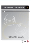
1
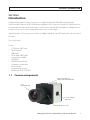
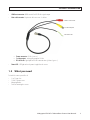
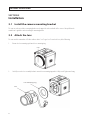
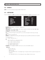
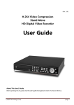
BLK-HDC20 2 Megapixel Full-HD C-mount Box Camera User Manual Please read this manual before using your camera, and always follow the instructions for safety and proper use. Save this manual for future reference. BLK-HDC20_CM ! WARNING CAUTION Changes or modifications not expressly approved by the manufacturer could void the user’s authority to operate the equipment. To prevent electric shock and risk of fire hazards, use a power source that is within specification only. Do NOT expose this appliance to rain or moisture. REGULATORY NOTICE This equipment may generate or use radio frequency energy. Changes or modifications to this equipment may cause harmful interference unless the modifications are expressly approved in the instruction manual. The user could lose the authority to operate this equipment if an unauthorized change or modification is made. REGULATORY INFORMATION : FCC Part 15 This equipment has been tested and found to comply with the limits for a Class A digital device, pursuant to Part 15 of the FCC Rules. These limits are designed to provide reasonable protection against harmful interference when the equipment is operated in a commercial environment This equipment generates, uses, and can radiate radio frequency energy and, if not installed and used in accordance with the instruction manual, may cause harmful interference to radio communications. Operation of this equipment in a residential area is likely to cause harmful interference in which case the user will be required to correct the interference at his own expense. LEGAL NOTICE Observint Technologies (Observint) products are designed to meet safety and performance standards with the use of specific Observint authorized accessories. Observint disclaims liability associated with the use of non-Observint authorized accessories. The recording, transmission, or broadcast of any person’s voice without their consent or a court order is strictly prohibited by law. Observint makes no representations concerning the legality of certain product applications such as the making, transmission, or recording of video and/or audio signals of others without their knowledge and/or consent. We encourage you to check and comply with all applicable local, state, and federal laws and regulations before engaging in any form of surveillance or any transmission of radio frequencies. Other trademarks and trade names may be used in this document to refer to either the entities claiming the marks and names or their products. Observint disclaims any proprietary interest in trademarks and trade names other than its own. No part of this document may be reproduced or distributed in any form or by any means without the express written permission of Observint. © 2012 by Observint, Inc. All Rights Reserved. 11000 N. Mopac Expressway, Building 300, Austin, TX 78759 For Sales and Support, please contact your distributor. ii PRECAUTIONS WARNING - Do not install this equipment in a confined space such as a bookcase or similar unit. WARNING - Wiring methods shall be in accordance with the National Electric Code, ANSI/NFPA 70. WARNING - This is a class A product. In a domestic environment this product may cause radio interference in which case the user may be required to take adequate measures. WARNING - To reduce a risk of fire or electric shock, do not expose this product to rain or moisture. CAUTION - Installation should be performed by a qualified service person and should conform to all local codes. CAUTION - To avoid electrical shock, do not open the camera enclosure. Refer servicing to qualified personnel only. CAUTION - This camera should not be exposed to water (dripping or splashing) and no objects filled with liquids, such as vases, should be placed on it. CAUTION - Danger of explosion if battery is incorrectly replaced. Replaced only with the same or equivalent type recommended by the manufacturer. Dispose of used batteries according to the manufacturer’s instructions. A suitable conduit entries, knock-outs or glands shall be provided in the cable entries of this product in the end use. Holes in metal, through which insulated wires pass, shall have smooth well rounded surfaces or shall be provided with bushings. DISPOSAL OF YOUR OLD APPLIANCES 1. All electrical and electronic products should be disposed of separately from the municipal waste stream via designated collection facilities appointed by the government or local authorities. 2. The correct disposal of your old appliance will help prevent potential negative consequences for the environment and human health. 3. For more detailed information about disposal of your old appliance, please contact your city office, waste disposal service or the shop where you purchased the product. To disconnect power from the mains, pull out the mains cord plug. When install the product, ensure that the plug is easily accessible. 2 Megapixel Full-HD C-Mount Box Camera User Manual iii IMPORTANT SAFETY INSTRUCTIONS IMPORTANT SAFETY INSTRUCTIONS 1. Read these instructions - All these safety and operating instructions should be read before the product is operated. 2. Keep these instructions - The safety, operating and user instructions should be retained for future reference. 3. Heed all warnings - All warnings on the product and in the operating instructions should be adhered to. 4. Follow all instructions - All operating and user instructions should be followed. 5. Do not use this apparatus near water - For example : near a bath tub, wash bowl, kitchen sink, laundry tub, in a wet basement; near a swimming pool; etc. 6. Clean only with dry cloth - Unplug this product from the wall outlet before cleaning. Do not use liquid cleaners. 7. Do not block any ventilation openings. Install in accordance with the manufacturer’s instructions. - Slots and openings in the cabinet are provided for ventilation, to ensure reliable operation of the product, and to protect it from overheating. The openings should never be blocked by placing the product on a bed, sofa, rug or other similar surface. This product should not be placed in a built-in installation such as a bookcase or rack unless proper ventilation is provided and the manufacturer’s instructions have been adhered to. 8. Do not install near any heat sources such as radiators, heat registers, stoves, or other apparatus (including amplifiers) that produce heat. 9. Do not defeat the safety purpose of the polarized or grounding-type plug. A polarized plug has two blades with one wider than the other. A grounding type plug has two blades and a third grounding prong. The wide blade or the third prong are provided for your safety. If the provided plug does not fit into your outlet, consult an electrician for replacement of the obsolete outlet. 10. Protect the power cord from being walked on or pinched particularly at plugs, convenience receptacles, and the point where they exit from the apparatus. 11. Only use attachments/accessories specified by the manufacturer. 12. Use only with the cart, stand, tripod, bracket, or table specified by the manufacturer, or sold with the apparatus. When a cart is used, use caution when moving the cart/apparatus combination to avoid injury from tip-over. 13. Unplug this apparatus during lightning storms or when unused for long periods of time. 14. Refer all servicing to qualified service personnel. Servicing is required when the apparatus has been damaged in any way, such as power supply cord or plug is damaged, liquid has been spilled or objects have fallen into the apparatus, the apparatus has been exposed to rain or moisture, does not operate normally, or has been dropped. iv TABLE OF CONTENTS Table of Contents SECTION 1 SECTION 2 SECTION 3 SECTION 4 APPENDIX A APPENDIX B PRECAUTIONS . . . . . . . . . . . . . . . . . . . . . . . . . . . . . . . . . . . . . . . . . . . . . . . . . . . . . . . . . . . . . . . . . . . . . . . . . . . . iii DISPOSAL OF YOUR OLD APPLIANCES. . . . . . . . . . . . . . . . . . . . . . . . . . . . . . . . . . . . . . . . . . . . . . . . . . . . . . . . . iii IMPORTANT SAFETY INSTRUCTIONS. . . . . . . . . . . . . . . . . . . . . . . . . . . . . . . . . . . . . . . . . . . . . . . . . . . . . . . . . . iv Introduction . . . . . . . . . . . . . . . . . . . . . . . . . . . . . . . . . . . . . . . . . . . . . . . . . . . . . . . . . . . . . . . . . . . . . . . . 1 1.1 Camera components. . . . . . . . . . . . . . . . . . . . . . . . . . . . . . . . . . . . . . . . . . . . . . . . . . . . . . . . . . . . . . . . . .1 1.2 What you need. . . . . . . . . . . . . . . . . . . . . . . . . . . . . . . . . . . . . . . . . . . . . . . . . . . . . . . . . . . . . . . . . . . . . . 3 Installation . . . . . . . . . . . . . . . . . . . . . . . . . . . . . . . . . . . . . . . . . . . . . . . . . . . . . . . . . . . . . . . . . . . . . . . . . 4 2.1 Install the camera mounting bracket. . . . . . . . . . . . . . . . . . . . . . . . . . . . . . . . . . . . . . . . . . . . . . . . . . . . 4 2.2 Attach the lens . . . . . . . . . . . . . . . . . . . . . . . . . . . . . . . . . . . . . . . . . . . . . . . . . . . . . . . . . . . . . . . . . . . . . . 4 Configuration Setup. . . . . . . . . . . . . . . . . . . . . . . . . . . . . . . . . . . . . . . . . . . . . . . . . . . . . . . . . . . . . . . . . . 7 3.1 Menu operation . . . . . . . . . . . . . . . . . . . . . . . . . . . . . . . . . . . . . . . . . . . . . . . . . . . . . . . . . . . . . . . . . . . . . 7 3.2 MODEL . . . . . . . . . . . . . . . . . . . . . . . . . . . . . . . . . . . . . . . . . . . . . . . . . . . . . . . . . . . . . . . . . . . . . . . . . . . . . 8 3.3 EXPOSURE . . . . . . . . . . . . . . . . . . . . . . . . . . . . . . . . . . . . . . . . . . . . . . . . . . . . . . . . . . . . . . . . . . . . . . . . . . 8 3.4 WHITE BALANCE. . . . . . . . . . . . . . . . . . . . . . . . . . . . . . . . . . . . . . . . . . . . . . . . . . . . . . . . . . . . . . . . . . . . . 9 3.5 IMAGE. . . . . . . . . . . . . . . . . . . . . . . . . . . . . . . . . . . . . . . . . . . . . . . . . . . . . . . . . . . . . . . . . . . . . . . . . . . . . 10 3.6 INTELLIGENCE . . . . . . . . . . . . . . . . . . . . . . . . . . . . . . . . . . . . . . . . . . . . . . . . . . . . . . . . . . . . . . . . . . . . . . 11 3.7 SPECIAL FUNCTION. . . . . . . . . . . . . . . . . . . . . . . . . . . . . . . . . . . . . . . . . . . . . . . . . . . . . . . . . . . . . . . . . . 12 3.8 DISPLAY. . . . . . . . . . . . . . . . . . . . . . . . . . . . . . . . . . . . . . . . . . . . . . . . . . . . . . . . . . . . . . . . . . . . . . . . . . . 13 Specifications . . . . . . . . . . . . . . . . . . . . . . . . . . . . . . . . . . . . . . . . . . . . . . . . . . . . . . . . . . . . . . . . . . . . . . 14 Troubleshooting. . . . . . . . . . . . . . . . . . . . . . . . . . . . . . . . . . . . . . . . . . . . . . . . . . . . . . . . . . . . . . . . . . . . 16 Camera Dimensions. . . . . . . . . . . . . . . . . . . . . . . . . . . . . . . . . . . . . . . . . . . . . . . . . . . . . . . . . . . . . . . . . 17 2 Megapixel Full-HD C-Mount Box Camera User Manual v vi SECTION 1: INTRODUCTION SECTION 1 Introduction This high definition indoor C/CS mount camera features 2.2 megapixel imaging with 1920 x 1080 resolution along with 3-dimensional Noise Reduction (3D-NR). 3D-NR automatically provides a more accurate noise reduction. This is based on twice the visual information than conventional field-based types. The video noise is reduced by 30 % in low light for a 2 dB improvement in the signal-to-noise ratio. The result is a brighter picture with less noise, even in low light. High definition video – HDcctv security cameras deliver true 1080p or 720p HD video, true HDTV-quality video in live and recorded view modes. A lens is not included Features • • • • • • • • • • • 1/3” Panasonic CMOS sensor Full HD Resolution HDMI output HD SDI output (SMPTE 292M) Composite video out (BNC) DAY & NIGHT WDR (Wide Dynamic Range) Defog, privacy mask functions On Screen Display Intelligent motion detection Multi Protocol (PELCO-D, PELCO-P) 1.1 Camera components Camera holder hole (upper side and underside) Lens (not provided) Lens iris output connector Flange-back set screw 2 Megapixel Full-HD C-Mount Box Camera User Manual 1 SECTION 1: INTRODUCTION NOTES: • • • • Lens: The camera accommodates a standard C or CS mount lens. Camera holder hole: Provided on the upper side and underside of the camera housing. Flange back (back focus) set screw: Used to lock the flange back. The adjustment is required only when a lens without focus-adjusting mechanism is mounted, or when a lens with adjusting mechanism is mounted and more accurate focus that is needed. Lens iris output connector: 4-pin connector used to send the Iris control signal and power supply to an auto-iris type lens. NOTE: Use only direct-drive or DC-drive lenses with this connector. 2 4 1 Pin DC -type lenses 1 Damping - 2 Damping + 3 Drive + 4 Drive - 3 1.1.1 Camera back panel Joystick OSD controls HDMI out connector HD-SDI video out terminal Main cable terminal Power LED BLK-HDC10 back connectors NOTES: • • 2 HD-SDI video out terminal BNC terminal for HD-SDI video signal output Joystick, OSD controls: Used to navigate the OSD menus See “3.1 Menu operation” on page 7 for more information. SECTION 1: INTRODUCTION • • HDMI out connector: HDMI terminal for HD-SDI video signal output. Main cable terminal: 6 pin main cable connector. See below Power connector C video output RS-485 leads —— —— —— • Power connector: 12 Vdc (center +) C video output: analog video output or C-Video RS-485 leads: Signal port for RS-485 communication (yellow +/ green -) Power LED - LED lights when the power is applied to the camera. 1.2 What you need To install the camera you will need: • • • • C- or CS-type lens 12 Vdc 1 A power source Mounting bracket Tools for mounting the camera 2 Megapixel Full-HD C-Mount Box Camera User Manual 3 SECTION 2: INSTALLATION SECTION 2 Installation 2.1 Install the camera mounting bracket The camera can be attached to a mounting bracket on the upper side or the underside of the camera. Always follow the manufacture’s guidelines when installing the mounting bracket. 2.2 Attach the lens The camera will accommodate a DC-drive or direct-drive C- or CS-type lens. To attach the lens, do the following: 1. Remove the lens mounting cap from the lens mounting ring. Cap 2. Carefully screw the lens assembly clockwise onto the lens mounting ring until it is fully seated. Tighten until snug. Lens mounting ring Lens 4 SECTION 2: INSTALLATION 3. If you installed an auto-iris lens, verify that the cable pin definitions match the lens output iris connector (see “1.1 Camera components” on page 1) then plug the cable into the lens iris output connector. Lens iris output connector 4. Follow the manufacturer’s instructions to attach the camera mounting bracket to the mounting surface. 5. Attach the camera to camera mounting bracket. 6. Attach the main cable to the main cable terminal on the back of the camera. 7. If you are controlling the camera through an RS-485 network, connect the main cable yellow (RS-485+) and green (RS‑485–) leads to your network. See “1.1.1 Camera back panel” on page 2 for more information. 8. Connect the C-video output connector to a local setup monitor (optional). (Use a setup monitor while making installation setup adjustments to the camera.) 9. Connect the camera HDMI connector or the HD-SDI connector to a DVR or monitor with HD capabilities using suitable cable. 10. Connect the main cable power connector to your powering source in compliance with local codes. If using 12 Vdc to power the camera, ensure that the center terminal of the mating connector is positive (+). 11. Verify that the POWER LED on the back of the camera is lit. 12. Power on the local setup monitor 13. While observing the image from the camera on the monitor, adjust the camera for the desired field of view: a. Adjust the mounting bracket to center the field of view in the camera image. b. Adjust the lens zoom and focus following the manufacturer’s suggested method. 2 Megapixel Full-HD C-Mount Box Camera User Manual 5 SECTION 2: INSTALLATION NOTE If you installed a lens without focus-adjusting mechanism, or a sharper focus is needed after adjusting the lens focus: - Loosen the flange back (back focus) set screw with a hex wrench, then rotate the flange until the best focus is achieved. - Tighten the flange back set screw until it is snug. 14. Configure your camera using the software menus in the on-screen display (OSD). Refer to “SECTION 3 Configuration Setup” on page 7 for more information. 15. If you used a setup monitor to configure the camera, disconnect it from the camera. 6 SECTION 3: CONFIGURATION SETUP SECTION 3 Configuration Setup Use the on-screen display (OSD) menus to configure your camera for the environment where it is installed and recording requirements you prefer. 3.1 Menu operation Navigation through the configuration menus (OSD) is performed with the joystick located on the camera back panel. The joystick will rock up, down, left and right, and is pressed in (to the camera) to select an item. Joystick • • • • • Rock Up p : Moves the cursor upwards in the menu. Use this button to select an item or adjust the parameters. Rock Down q : Moves the cursor downwards in the menu. Use this button to select an item or adjust the parameters. Rock Right u : Moves the cursor to the right in the menu. Use this button to select or adjust the parameters of the selected item. The parameter changes each time this button is pressed. Rock Left t : Moves the cursor to the left in the menu. Use this button to select or adjust the parameters of the selected item. The parameter changes each time this button is pressed. Press Down (Select) : Opens the OSD menu system and executes selections and displays a submenu for an item with the mark. Press the Set button to open the OSD main MENU consists of a list of sub-menus or displays the option selected for a camera function. When sub-menus are available, the symbol is shown. 2 Megapixel Full-HD C-Mount Box Camera User Manual 7 SECTION 3: CONFIGURATION SETUP 3.2 MODEL MODEL: Select model type: D&N (day and night) / COLOR / IR SMART / IR CDS 3.3 EXPOSURE To open the EXPOSURE menu, rock the joystick down (or up) to highlight EXPOSURE, then press the joystick down (set, select). • • • • • • • • • BRIGHTNESS: Adjust brightness level: 0 (dark) ~ 20 (bright) steps LENS: DC / MANUAL SHUT SPEED: Can be set in AUTO or MANUAL: AUTO / 1/30 (25), 1/60 (50), 1/120 (100), 1/240, 1/500, 1/1000, 1/2000, 1/4000, 1/8000, 1/16000,1/30000, 1/60000 s FLICKERLESS: Set to On or Off for best video performance. Normally OFF. DSS: Select maximum DSS (Digital Slow Shutter): OFF / x2, x3, x4. This feature improves the video image in low-light conditions. AGC: Select Auto Gain Control OFF / ON WDR/BLC: Select WDR (Wide Dynamic Range) or BLC (Back Light Compensation). NOTE: When WDR is ON, ACE and DEFOG function will not turn on. —— WEIGHT : Adjust WDR level 0 ~ 3 BLC —— AREA : Control BLC area according to light condition. —— POS-X : Adjust the window X-Axis position —— POS-Y : Adjust the window Y-Axis position —— SIZ-X : Adjust the window X-Axis size —— SIZ-Y : Adjust the window Y-Axis size DAY&NIGHT : Select Day&Night. The MODEL mode determines content of the DAY&NIGHT submenu. D&N Model —— AUTO / DAY / NIGHT / EXT »» Delay : 0 ~ 255 second »» BURST : OFF / ON »» THRS : LOW / MIDDLE / HIGH. Select Day&Night change level. Higher level make the night mode changed in lower illumination. »» GAP : LOW / MIDDLE / HIGH: Select Day to Night mode change and Night to Day mode change. 8 SECTION 3: CONFIGURATION SETUP COLOR Model —— —— —— —— —— AUTO / DAY / NIGHT / EXT Delay : 0 ~ 255 second BURST : OFF / ON THRS : LOW / MIDDLE / HIGH GAP : LOW / MIDDLE / HIGH IR SMART Model (not used with this camera) IR CDS Model (not used with this camera) • SMART IR : OFF / ON. NOTE: SMART IR function only works with IR Smart Model. —— THRS : Set-up Smart IR turns on point. When you level up the value, Smart IR turns on in a low light condition. —— AREA : Set up areas to control Smart IR function. When BLC mode is on, Smart IR area is following BLC area. —— POS-X : Adjust the window X-Axis position —— POS-Y : Adjust the window Y-Axis position —— SIZ-X : Adjust the window X-Axis size —— SIZ-Y : Adjust the window Y-Axis size —— IR COMP : Compensate when IR hunting happens. When you use this function, you should put a test object around 30 cm form the camera. If an object is located in nearer than 30 cm from the camera and an object what could reflect the light is in front of the camera, the camera cannot compensate a trouble of hunting. 3.4 WHITE BALANCE • • AWB : Select WHITE BALANCE mode. AUTO / PRESET / MANUAL / INDOOR / OUTDOOR —— AUTO : Automatically adjusts color according to the lighting. —— PRESET : It is a fixed white balance mode that may be automatically readjusted only by pressing PRESET —— MANUAL : You can change WB as changing “RED GAIN” and “BLUE GAIN” in manual mode. »» RED GAIN : Adjust R gain value 0 ~ 20 »» BLUE GAIN : Adjust B gain value 0 ~ 20 —— INDOOR : Set color temperature to be Indoor light (3700 K) —— OUTDOOR : Set color temperature to be Outdoor light (5100 K) CHROMA : Adjust CHROMA gain value 0 ~ 20 steps 2 Megapixel Full-HD C-Mount Box Camera User Manual 9 SECTION 3: CONFIGURATION SETUP 3.5 IMAGE • • SHARPNESS : Adjust sharpness level: 0 ~ 10 steps MIRROR : Select a flip mode: OFF / H / V / H&V —— H : You can flip the picture horizontally on the screen —— V : You can flip the picture vertically on the screen —— H&V : You can flip the picture horizontally & vertically on the screen H Mirror Off • • • • 10 H Mirror ON Freeze : Select real or still mode: OFF / ON E.ZOOM : Select maximum digital zoom magnification: x1 ~ x12, x14, x15, x18, x21, x25, x32 HLC : Select High Light Compensation. When extremely bright light is projected to the camera masking is used on the portion to prevent partial saturation on the monitor: OFF / ON —— ON LEVEL : 0 ~ 20 steps. COLOR : Black, White, Yellow, Cyan, Green, Magenta, Red, Blue ACE : Select Digital WDR (Wide Dynamic Range): OFF / ON. NOTE: When ACE is On, WDR/BLC and DEFOG function can not turn on. SECTION 3: CONFIGURATION SETUP WDR Off • • • WDR ON DNR : Select Digital Noise Reduction: AUTO / OFF / LOW / MIDDLE / HIGH D.COMPRESS : Use this function only with IP camera. Set to OFF. GAMMA: Set gamma level for best display 3.6 INTELLIGENCE • PRIVACY : Hide an area you want to hide on the screen: OFF / ON —— MASK# : Select mask area number (0 ~ 31) —— MODE : Set-up masking areas. (OFF / ON) —— X-POS : Adjust the mask X-Axis position —— Y-POS : Adjust the mask Y-Axis position —— X-SIZ : Adjust the mask X-Axis size —— Y-SIZ : Adjust the mask Y-Axis size —— COLOR : Cyan, Green, Magenta, Red, Blue, Black, White, Yellow —— TRANS : Select mask transparency level (0 ~ 4) 2 Megapixel Full-HD C-Mount Box Camera User Manual 11 SECTION 3: CONFIGURATION SETUP 3.7 SPECIAL FUNCTION • • • • • • • • • • SHADING DET : Sets the shading calibration that the lens will perform. Only occurs when the entire screen is viewed in white light. (OFF / ON) SHADING : Select Lens shading compensation. (OFF / ON) DEFECT DET : Compensates for bad pixels that my occur. Occurs when the whole screen is in full black or if there is bad pixelation and it changes the THRS values until the screen is fixed. (OFF / ON) DEFOG : Carry out defog function: OFF / ON —— LEVEL : adjust amount of fog on display screen: 0 ~ 10. NOTE: When DEFOG is On, ACE and WDR/BLC function can not turn on. SYSTEM : Select NTSC or PAL. (NTSC / PAL) HD FORMAT : Select Digital output 1080P or 720P. (1080P / 720P) PG* : Select Color pattern generator (OFF / ON) CVBS : Select Composite signal (OFF / ON) COMM : Set up the camera ID, baud rate, protocol —— ID : Select the camera ID: 1 ~ 255 —— BAUD RATE : Select serial communication speed: 2400 / 4800 / 9600 / 19200 / 38400 / 57600 / 115200 bps —— PROTOCOL : Select operating protocol: PELCO-D / PELCO-P / UPDATE DEFAULT : All the settings will be restored to the factory default. * PG (Pattern Generator), PRIVACY MASK, MOTION AREA cannot work simultaneously, PG has priority, second is PRIVACY MASK and lastly, MOTION AREA. For example, if PG ON is selected while PRIVACY MASK is active, PRIVACY MASK stops and PG is active. 12 SECTION 3: CONFIGURATION SETUP 3.8 DISPLAY • • DISP SEL : Select display item. —— ID : OFF / ON —— TITLE : OFF / ON —— EZOOM : OFF / ON SET TITLE : Select camera title menu (Text edit) Set Title character set (on-screen) 2 Megapixel Full-HD C-Mount Box Camera User Manual 13 SECTION 4: SPECIFICATIONS SECTION 4 Specifications Table 1. Component Specifications Component Value Image Sensor 1/3" Panasonic CMOS Total Pixels 2010 (h) x 1108 (v) = 2,227,080 (pixels) Active Pixels 1944 (h) x 1092 (v) = 2,122,848 (pixels) Scanning system Progressive Resolution Digital : 1920 x 1080 (1080p / 30 fps), 1280 x 720 (720p / 60fps) Analog : 700 TVL Min. Illumination Color : 1.0 lux , B/W : 0.5 lux Color DSS : 0.002 lux , BW DSS : 0.001 lux Video output HD-SDI Analog : NTSC, PAL (without WDR) S/N ratio > 50 dB (AGC off) Function MODEL D&N / COLOR / IR SMART / IR CDS EXPOSURE BRIGHTNESS 0 ~ 20 steps LENS DC / Manual SHUT SPEED Auto / Manual ( 1/30 (1/25) ~ 1/60000 ) DSS Off / x2 / x3 / x4 AGC Off / On WDR/BLC Off / WDR / BLC DAY&NIGHT Auto / Day / Night / Ext SMART IR N/A WHITE BAL Auto / Preset / Manual / Indoor / Outdoor IMAGE SHARPNESS 0 ~ 10 steps MIRROR Off / H / V / H&V FREEZE Off / On E.ZOOM x1 ~ x32 HLC Off / On ACE Off / On 14 SECTION 4: SPECIFICATIONS Component Value DNR Off / Low / Middle / High / Auto D.COMPRESS OFF / ON INTELLIGENCE PRIVACY Off / On (32 points) MOTION Off / On (4 points) SPECIAL FUNC SHADING DET Off / On SHADING Off / On DEFECT DET Off / On DEFOG Off / On SYSTEM NTSC / PAL HD FORMAT 1080p / 720p PG Off / On CVBS Off / On COMM ID (1 ~ 255) Baud rate: 2400 / 4800 / 9600 / 19200 / 38400 / 57600 / 115200, protocol: PELCO-P / PELCO-D / UPDATE DEFAULT ON / DONE Language English OSD Text 0~9,A~Z,a~z Electrical Power Source 12 Vdc ± 10 % Current 250 mA (12 Vdc ± 10 %) General Power Input DC JACK Video Output (HD-SDI) BNC connector Operating Temperature +14 °F ~ +122 °F (-10 °C ~ +50 °C), Humidity : 0 % RH ~ 80 % RH Storage Temperature -4 °F ~ +140 °F (-20 °C ~ +60 °C), Humidity : 0 % RH ~ 90 % RH 2 Megapixel Full-HD C-Mount Box Camera User Manual 15 APPENDIX A: TROUBLESHOOTING APPENDIX A Troubleshooting If you experience problems you cannot resolve, please contact your distributor. Problem Solution Nothing appears on the screen. - Check the power connections. - Check the video cable connections. - Ensure that the lens mode is set to DC (VIDEO) when using a VIDEO (DC) lens. The video image is not clear. - Clean the lens with a soft, clean cloth. - Adjust the monitor screen for room lighting conditions. Move the camera if necessary. The screen is dark. - Adjust the contrast feature of the monitor. - If you have an intermediate device, set the 75Ω /Hi-Z properly, and check the terminals. - If an auto iris lens is being used, adjust the brightness level. The MOTION DETECTION function is not working - Is “MOTION DETECTION” mode turned on? - Is the MD Sensitivity set too low? Increase the sensitivity. - Check the setting of the MD AREA. The WDR function is not working - Is the WDR level too low? - Is the AE Mode set to MANUAL? WDR is disabled in MANUAL exposure mode. Colors are not quite right. - Is the camera facing directly into sunlight or fluorescent light? - Is an auto-iris lens being used? Adjust if necessary. - Check the connection of the lens connector cable. The Day&Night function doesn’t work. - Is the AGC (EXPOSURE menu) set to OFF? The Auto Day&Night Function doesn’t work if the AGC is OFF. - Check the D <—> N level. 16 APPENDIX B: CAMERA DIMENSIONS APPENDIX B Camera Dimensions 2.60” 1.97” 2,17” 2.32” Side Front 2 Megapixel Full-HD C-Mount Box Camera User Manual 17