1
Z16C30 USC®
USER'S MANUAL
ZILOG
SERIAL & PROTOCOL QUESTIONS AND ANSWERS (Continued)
Q: Running asynchronous mode, how do you program a
USC family device to achieve a certain baud rate with
a predetermined external clock? That is, do you need
to use the DPLL, BRG, CTR, or certain encoding
methods?
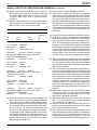
A: Below are three baud rate and clock rate examples.
The only encoding method allowed for async mode is
NRZ. The DPLL is not used in async mode.
EXAMPLE
BAUD RATE
CLK RATE
DIVISOR
#1
2400
76800
76800/
2400=32
16
64
#2
#3
1M
9600
16M
614400
(1) To achieve : 2400 baud
With ext clk
: 76800 Hz
You need
: 76800 / 2400 = 32X
H/W setup
: RxC pin —> BRG0 —> RxCLK
Set registers: CMR(D13-12)=00 for 16X divisor
TC0R =01h for BRG0 divisor
Validation
: 16X times 2 = 32X
(2) To achieve : 1M baud
With ext clk
: 16 MHz
You need
: 16M / 1M = 16X
H/W setup
: RxC pin —> RxCLK
Set registers: CMR(D13-12)=00 for 16X divisor
TC0R =00h for no divide
Validation
: 16X times 1 = 16X
(3) To achieve : 9600 baud
With ext clk
: 6.144 kHz
You need
: 6.144K / 9.6K = 64X
H/W setup
: RxC pin —> BRG0 —> RxCLK
Set registers: CMR(D13-12)=00 for 16X divisor
TC0R =03h for BRGo divisor
Validation
: 16X times 4 = 64X
Q: When the USC gets an RCC underrun condition, the
device will issue a Device Status Interrupt instead of
the expected Receive Status. What should be done?
A: If the channel ever sets RCCUnder Latched/Unlatched
and interrupts, the processor should clear the condition by writing a 1 to the L/U bit, discard the data
received for the frame(s) by purging the RxFIFO,
reprogram the receive DMA controller if one is being
used, and do whatever else is necessary to clean up
the situation. Then write the “Enter Hunt Mode” command to the RCmd field of the Receive Command/
Status Register (RCSR 15-12)
B-4
Q: Is there a trick to using “Wait2Send” feature?
A: “Wait To Send” works by intercepting the data valid
signal from the FIFO to the transmitter, which has the
effect of stopping transmission at the end of a frame.
This works only when the last byte in the frame is
marked as EOF either explicitly or by using the TCC.
Note that this does not stop DMA requests or interrupt
requests. These signals from the FIFO are not touched
so that data for the next frame will be requested by the
part as soon as the EOF byte is transferred to the
transmitter.
Q: Does CRC16 work the same way as CRC32 in HDLC?
A: In HDLC the CRC is inverted before transmission.
Mathematically this has the effect of forcing a remainder to be present when the CRC calculation is complete. This remainder is a function of the CRC polynomial used, and the USC family is capable of checking
for the proper remainder for the CRC-CCITT polynomial for a 16-bit CRC and the Ethernet polynomial for
a 32-bit CRC. When the CRC-16 polynomial is selected in HDLC mode, it does not work because the
part does not check for the corresponding remainder.
Q: When using multiple USC family devices at separate
stations in HDLC Loop mode, some of the clock jitter
from one station’s receive path onto its transmit path
may increase the error rate. How does the USC family
eliminate this problem?
A: The on-board DPLL will automatically adjust and recover the clock information from the data stream, but
there is no way to eliminate the jitter. At a fundamental
level, the jitter is due to the timing differences between
the local oscillators at the various stations in the loop.
Thus, the limit on the number of stations in the loop, for
error-free transmission, is determined by the local
oscillator tolerance (in nanoseconds), multiplied by
the number of stations in the loop. This product must
be less than one half of a bit time for the loop to function
properly.
Q: What is the maximum bit rate in synchronous mode
with clock recovery from data stream, Manchester
encoding/decoding, and the master clock for USC
family device operating at 20 MHz?
A: Manchester (Biphase-Level) requires the use of the
DPLL. The minimum DPLL divisor is eight, which will
give a data rate of 2.5 Mbit/sec.
Q: Should I use the counters in a USC family device to
have a more stable transmit clock source when I drive
the receiver with the DPLL output?
A: The counters would provide a stable transmit clock
from a common source when the DPLL is providing the
receive clock. The 5-bit counters, which can be programmed to divide an input clock by 4, 8, 16, or 32, can
be used as prescalers for the baud rate generators.
UM97USC0100