1
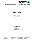
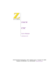
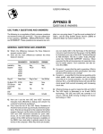
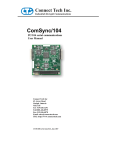
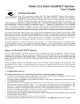
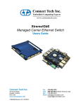
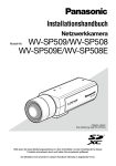
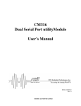
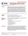
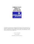
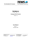
USER MANUAL
ComSync/PCI-104
CTIM-00048 (0.00) - October 31, 2008
ComSync/PCI-104 User Manual
Table of Contents
Table of Contents ................................................................................................................................................2
Introduction.........................................................................................................................................................3
Features ...............................................................................................................................................................3
System Overview ................................................................................................................................................4
Hardware Installation ..........................................................................................................................................5
Slot Selection Rotary Switch (RSW1) ...........................................................................................................5
Software Development........................................................................................................................................6
Hardware Information ....................................................................................................................................6
PCI Configuration Space................................................................................................................................6
Decoded Address Map ...................................................................................................................................7
PCI Base Address Register 2 (PCIBAR2)......................................................................................................7
FPGA Register Descriptions ..........................................................................................................................9
PCI Base Address Register 3 (PCIBAR3)....................................................................................................12
DMA Support...............................................................................................................................................12
Interrupts ......................................................................................................................................................12
System Block Diagrams ...............................................................................................................................13
Duplex Modes ..............................................................................................................................................15
IUSC Clock Control .....................................................................................................................................16
Software Selectable Line Interface Modes...................................................................................................18
Connecting Serial Devices ...........................................................................................................................19
V.28 Connections ....................................................................................................................................19
RS-422/V.11 Connections .......................................................................................................................19
ComSync/PCI-104 Synchronous Clocking ..................................................................................................20
Loopback Connectors...................................................................................................................................20
Connector Pinouts ........................................................................................................................................21
PCI-104 Header (P1) ...............................................................................................................................21
Appendix...........................................................................................................................................................22
ComSync/PCI-104 Specifications ................................................................................................................22
Operating Environment ...........................................................................................................................22
Communications......................................................................................................................................22
ESD Protection ........................................................................................................................................22
Power.......................................................................................................................................................22
Connectors...............................................................................................................................................22
Dimensions ..............................................................................................................................................22
Cable Options ..........................................................................................................................................22
I/O Connect Pin Assignments ......................................................................................................................23
Multi-drop communications using V.11/RS-422/485 line modes ................................................................24
Asynchronous Communications Tutorial.....................................................................................................24
Serial Line Interface Tutorial .......................................................................................................................25
RS-232 Line Interface: ............................................................................................................................25
Differential Line Interface: ......................................................................................................................25
Multi-drop 4-Wire, Full Duplex Communications: .................................................................................26
Basic 2-Wire, Half Duplex Multi-drop Connection: ...............................................................................27
Termination Resistors in Differential Networks......................................................................................28
Limited Lifetime Warranty ...............................................................................................................................29
Copyright Notice...............................................................................................................................................29
Trademark Acknowledgement ..........................................................................................................................29
Customer Support Overview.............................................................................................................................30
Contact Information ..........................................................................................................................................30
CTIM-00048 (0.00) 10/31/2008
www.connecttech.com
800-426-8979 | 519-836-1291
2
ComSync/PCI-104 User Manual
Introduction
Connect Tech’s ComSync/PCI-104 is a two channel synchronous/asynchronous serial adapter card designed
for PCI-104 bus systems.
Multi-protocol ComSync/PCI-104 offers high performance and reliable communications for industrial and
embedded applications. ComSync/PCI-104 utilizes the features and functionality of the Zilog Z16C32
Integrated Universal Serial Controller along with a simple register structure to provide users with full
featured synchronous/asynchronous communications.
Features
•
•
•
•
•
•
•
•
•
3
PCI-104 form factor. Universal PCI 2.2 bus - 33MHz/32-bit PCI interface
Two software selectable synchronous/asynchronous serial ports
Supports two software programmable PCI Bus DMA (Direct Memory Access) channels to on-board
512KB SRAM.
Seven software selectable electrical interfaces: RS-232 (V.28), RS-422/485, RS-449(V.36), EIA-530,
EIA-530/A, V.35 and X.21 (V.11)
Multiple communication protocols supported; HDLC, SDLC, MonoSync, BiSync, Transparent BiSync,
Async, external character sync and others
Supports data encoding methods: NRZI, NRZB, NRZI-Mark, NRZI-Space, Biphase-Space (FM0),
Biphase-Mark (FM1), Biphase-Level (Manchester), Differential Biphase, Baud rates up to 20 Mbps
(synchronous, using special build options) 10 Mbps (synchronous, standard model), 230.4 Kbps
(asynchronous)
Software selectable internal and external clocking modes. External clocking is provided on TxC and
RxC pins.
Operating temperature range of 0°C to 70°C.
RoHS compliant
www.connecttech.com
800-426-8979 | 519-836-1291
CTIM-00048 (0.00) 10/31/2008
ComSync/PCI-104 User Manual
System Overview
Based on the PCI bus and a compact form factor, ComsSync/PCI-104 provides maximum flexibility. The
ComSync/PCI-104 enables users to choose from multiple electrical interfaces, protocols and encoding
schemes to provide a hardware solution that is ideally suited to each specific application.
ComSync/PCI-104 is PCI-104 1.0 compliant. Lifetime warranty and free technical support are included.
The following conceptual block diagram provides a high level overview of the ComSync/PCI-104 and
illustrates the general interconnection between components and connectors.
Figure 1: ComSync/PCI-104 Block Diagram
CTIM-00048 (0.00) 10/31/2008
www.connecttech.com
800-426-8979 | 519-836-1291
4
ComSync/PCI-104 User Manual
Figure 2: ComSync/PCI-104 Board Layout
Hardware Installation
The following section describes the function of the PCI slot selection rotary dip-switch. Be sure to establish
settings prior to the physical installation of the ComSync/PCI-104 adapter in your PCI-104 stack.
Slot Selection Rotary Switch (RSW1)
This rotary switch selects a slot position in the PCI-104 stack. When installing ComSync/PCI-104 in a stack,
ensure that the rotary switch matches the card position in the stack.
Table 1: Slot Selection (RWSI)
Position
Slot
0,4
0
1,5
1
2,6
2
3,7
3
5
www.connecttech.com
800-426-8979 | 519-836-1291
CTIM-00048 (0.00) 10/31/2008
ComSync/PCI-104 User Manual
Software Development
Hardware Information
This section offers information about how the ComSync/PCI-104 on-board functions can be accessed
through the PCI bus. Below are details about the PCI Bridge Configuration Space, the PCI Base Address
Registers, and detailed Memory Maps for each of the decoded Base Address Register regions that allow
access to the on-board SRAM, FPGA control and status registers, as well as, two Zilog Z16C32 Integrated
Universal Serial Controllers (IUSCs). This information is the framework for software development.
PCI Configuration Space
Accessibility to the on-board functions of the ComSync/PCI-104 is available via the PLX-9054 PCI-Bridge.
This PCI-Bridge accesses the on-board functions by mapping them to different PCI Base Address Registers
(PCIBARn). The contents of the PCI-Bridge’s 256-Byte PCI Configuration Space and the location of the
on-board functions as decoded by the PCI Base Address registers is illustrated in Table 2.
The SRAM is accessible to both the host (through the PCI-Bridge) and the two IUSCs. This accessibility is
the mechanism for running the two IUSCs in DMA mode.
The details of the operation of each of the registers are listed below.
PCI
Config.
Register
Address
Offset
(Hex)
0000
0004
0008
000C
0010
0014
0018
001C
0020
0024
0028
002C
0030
0034
Table 2: PCI-Bridge Configuration Space Description
Area Accessed
Area Accessed
Register Accessed
Bits
Bits
31………..16
15……………0
Device ID
Vendor ID
Status
Command
Class Code
Class Code /Bridge Rev ID
Bist | Header
PCI Bus LAT | Cache
PCI Base Address Space 0 (PCIBAR0)
PCI Base Address Space 1 (PCIBAR1)
PCI Base Address Space 2 (PCIBAR2)
PCI Base Address Space 3 (PCIBAR3)
PCI Base Address Space 4 (PCIBAR4)
PCI Base Address Space 5 (PCIBAR5)
Cardbus CIS Pointer
Subsystem ID
Subsystem Vendor ID
CTIM-00048 (0.00) 10/31/2008
Content
9054
|
10B5
0680
|
000B
0000
|
0100
0000
|
0000
Memory Mapped Config. Register
I/O Mapped Configuration Register
IUSC and FPGA Register Access
SRAM Access
Not Used
Not Used
Not Used
0800
|
12C4
www.connecttech.com
800-426-8979 | 519-836-1291
PCI
Writable
N
Y
N
Y
Y
Y
Y
Y
Y
Y
Y
N
6
ComSync/PCI-104 User Manual
The ComSync/PCI-104 has both IUSCs and FPGA control and status registers all mapped into the
PCIBAR2 memory region. The on-board SRAM is mapped into PCIBAR3. Table 3 below indicates the size
and function of the memory regions decoded by the different PCI Base Address Registers.
Decoded Address Map
Table 3: PCI Bridge – Base Address Registers
PCI
PCI BAR
Decoded
Configuration
Memory Size
Offset(Hex)
Item
IUSC and FPGA
internal registers
SRAM
18
PCIBAR2
8 Kbyte
Relative
Size(hex) of
Decoded
Memory
0x0000 1FFF
1C
PCIBAR3
512 KByte
0x0007 FFFF
PCI Base Address Register 2 (PCIBAR2)
As previously stated, the ComSync/PCI-104’s IUSC serial controllers, the FPGA control registers and the
FPGA status registers are mapped to the PCIBAR2 memory region. Table 4 below presents the Offset
Address of the internal registers of both IUSCs relative to PCIBAR2. Detailed information about how to
configure and control the IUSCs can be found in the Zilog Z16C32 Integrated Universal Serial Controller
User’s Manual, seen at http://www.zilog.com/docs/serial/um0140.pdf
Address
Offset
(in hex)
7
Table 4: Memory Map of PCIBAR2 – IUSC Registers
Area (item)
Register
Notes
Accessed
Accessed
0000
0002
0004
0006
0008
000A
000C
000E
0010
0012
0014
0016
0018
001A
001C
001E
0020
IUSC Area
IUSC-1
IUSC-1 Sreg [1]
IUSC-1 Sreg
IUSC-1 Sreg
IUSC-1 Sreg
IUSC-1 Sreg
IUSC-1 Sreg
IUSC-1 Sreg
IUSC-1 Sreg
IUSC-1 Sreg
IUSC-1 Sreg
IUSC-1 Sreg
IUSC-1 Sreg
IUSC-1 Sreg
IUSC-1 Sreg
IUSC-1 Sreg
IUSC-1 Sreg
IUSC-1 Sreg
CCAR
CMR
CCSR
CCR
PSR
PCR
TMDR
TMCR
CMCR
HCR
IVR
IOCR
ICR
DCCR
MISR
SICR
RDR(TDR)
0022
IUSC-1 Sreg
RMR
8/16 bit serial data (byte/word)
Writes go to the Transmitter FIFO
Reads come from the Receiver
FIFO
www.connecttech.com
800-426-8979 | 519-836-1291
CTIM-00048 (0.00) 10/31/2008
ComSync/PCI-104 User Manual
Address
Offset
(in hex)
0024
0026
0028
002A
002C
002E
0030
0032
0034
0036
0038
003A
003C
003E
0040→007F
0080->009F
00A0→00FE
0100
0102
0104
0106
0108
010A→0111
0112
0114
0116
0118
011A
011C
011E
0120→0129
012A
012C
012E
0130→0139
013A
013C
013E
0140→0181
0182
0184→019D
019E
Area (item)
Accessed
Register
Accessed
IUSC-1 Sreg
IUSC-1 Sreg
IUSC-1 Sreg
IUSC-1 Sreg
IUSC-1 Sreg
IUSC-1 Sreg
IUSC-1 Sreg
RCSR
RICR
RSR
RCLR
RCCR
TCOR
TDR(RDR)
IUSC-1 Sreg
IUSC-1 Sreg
IUSC-1 Sreg
IUSC-1 Sreg
IUSC-1 Sreg
IUSC-1 Sreg
IUSC-1 Sreg
--IUSC
Data FIFOs
(32 bytes)
TMR
TCSR
TICR
TSR
TCLR
TCCR
TC1R
--RDR/TDR
IUSC-1 Dreg [2]
IUSC-1 Dreg
--IUSC-1 Dreg
IUSC-1 Dreg
--IUSC-1 Dreg
IUSC-1 Dreg
--IUSC-1 Dreg
IUSC-1 Dreg
IUSC-1 Dreg
IUSC-1 Dreg
--IUSC-1 Dreg
IUSC-1 Dreg
IUSC-1 Dreg
--IUSC-1 Dreg
IUSC-1 Dreg
IUSC-1 Dreg
--IUSC-1 Dreg
--IUSC-1 Dreg
DCAR
TDMR
--DCR
DACR
--BDCR
DIVR
--DICR
CDIR
SDIR
TDIAR
--TBCR
TARL
TARU
--NTBCR
NTARL
NTARU
--RDMR
--RDIAR
CTIM-00048 (0.00) 10/31/2008
Notes
8/16 bit serial data (byte/word)
Writes go to the Transmitter FIFO
Reads come from the Receiver
FIFO
Aliases of addresses 00→3F
16 bit serial data transfers ONLY!
Writes go to the Transmitter FIFO
Reads come from the Receiver
FIFO
(useful for block data movements)
Aliases of 080->9F
Reserved, do not access
Reserved, do not access
Reserved, do not access
Reserved, do not access
Reserved, do not access
Reserved, do not access
Reserved, do not access
www.connecttech.com
800-426-8979 | 519-836-1291
8
ComSync/PCI-104 User Manual
Address
Offset
(in hex)
01A0→01A9
01AA
01AC
01AE
01B0→01B9
01BA
01BC
01BE
01C0→01FF
0200
0202→03FF
Area (item)
Accessed
Register
Accessed
Notes
--IUSC-1 Dreg
IUSC-1 Dreg
IUSC-1 Dreg
--IUSC-1 Dreg
IUSC-1 Dreg
IUSC-1 Dreg
--IUSC-1
IUSC-1
--RBCR
RARL
RARU
--NRBCR
NRARL
NRARU
---
Reserved, do not access
0400→05FF
IUSC-2
IUSC-2
0600
0602-07FF
IUSC-2
IUSC-2
As Above
Reserved, do not access
Reserved, do not access
Interrupt Acknowledge (read only)
Reserved, do not access
Same registers as addresses
000→1FF
Interrupt Acknowledge (read only)
Reserved, do not access
FPGA Register Descriptions
Again, the ComSync/PCI-104’s FPGA control and status registers are mapped to the PCIBAR2 memory
region. Table 5 below shows the Offset Address of the FPGA registers relative to PCIBAR2. The details of
the operation of each bit in the registers is also outlined in the description below.
Address
Offset
(in hex)
Table 5: Memory Map of PCIBAR – FPGA Register Summary
Area (item)
Register
Notes
Accessed
Accessed
1000
1002
1004
1006
1008
100A
100C
100E
1010
1012
1014→1FFF
9
FPGA Area
LEDC
LIFC1
LIFC2
FPGA_CNTRL
FPGA_STATUS
See “FPGA Registers” for details.
LED Control. 16 Bit Read/write
Alias of 1000
Serial Port-1 Line I/F control. 16 Bit
Read/Write
Alias of 1004
Serial Port-2 Line I/F control. 16 Bit
Read/Write
Alias of 1008
Control Bits. 16 Bit Read/Write
Alias of 100C
Status bits. 16 Bit Read Only.
Alias of 1010
Unused
www.connecttech.com
800-426-8979 | 519-836-1291
CTIM-00048 (0.00) 10/31/2008
ComSync/PCI-104 User Manual
Table 6: FPGA Register Detailed Description
Offset
1000
Reg.
Name
LEDC
R/W
Valid
Bits
R/W
D15..0
LED
Control
Register
1004
LIFC 1
Line
Interface
IUSC
‘1’Control
Register
1008
LIFC 2
Line
Interface
IUSC
‘2’Control
Register
Bit Descriptions
Reset
Values
(Hex)
0000
Control Bits: Read/Write only as a 16 Bit word.
15
X
14
X
13
X
12
X
11
X
10
X
9
X
8
X
Auto Flash Mode
7
6
5
X
X
X
4
X
NOTE: Auto Flash Mode (#AFM): 0 = LED automatically flashes every ½ second, a system heart beat.
1 = LED off.
X
Reserved for future use. Set to zero for Writes. Returns zero on Reads.
Control Bits: Read/Write only as a 16 Bit word.
15
14
13
12
11
10
9
8
7
6
5
4
X
X
X
X
X
X
X
X
X
X
42W
DM
Direct Mode
3
2
X
X
1
X
0
#AFM
0007
3
2
1
0
SPT
SP2
SP1
SP0
Basic Line Mode Control bits:
SP[2..0] SP508 Line Mode setting bits: See Table 10 for Line Interface Mode settings. Power-up state=[111]
SPT
SP508 Terminator Enable: (0=disable terminator, 1=enable terminator). Power up State = 0.
Duplex Control and RTS Pin Control bits:
DM
Duplex Mode selection: (0=Full, 1=Duplex)
42W
4/2 Wire mode selection: (0=2wire (or ½ Duplex), 1=4wire (or Multi-Drop Slave)
NOTE: See Duplex Modes for complete information on implementation
For Future Use
X
Reserved for future use. Set to zero for Writes. Returns zeros on Reads
Control Bits: Read/Write only as a 16 Bit word.
15
14
13
12
11
10
9
8
7
6
5
X
X
X
X
X
X
X
X
X
X
42W
4
3
2
1
0
DM
SPT
SP2
SP1
SP0
0007
Basic Line Mode Control bits:
SP[2..0] SP508 Line Mode setting bits: See Table 10 for Line Interface Mode settings. Power-up state=[111]
SPT
SP508 Terminator Enable: (0=disable terminator, 1=enable terminator). Power up State = 0.
Duplex Control and RTS Pin Control bits:
DM
Duplex Mode selection: (0=Full, 1=Duplex)
42W
4/2 Wire mode selection: (0=2wire (or ½ Duplex), 1=4wire (or Multi-Drop Slave)
NOTE: See Duplex Modes for complete information on implementation Duplex Modes
For Future Use
X
Reserved for future use. Set to zero for Writes. Returns zero on Reads.
CTIM-00048 (0.00) 10/31/2008
www.connecttech.com
800-426-8979 | 519-836-1291
10
ComSync/PCI-104 User Manual
Offset
100C
Reg.
Name
R/W
Valid
Bits
FPGA_
CNTRL
R/W
D15..0
Control
Bits
Bit Descriptions
Control Bits: Read/Write only as a 16 Bit word.
15
14
13
12
11
10
X
X
X
X
X
X
9
X
8
X
7
X
6
X
Reset
Values
(Hex)
5
IABT
4
MIE
3
X
2
X
1
SR[1]
0
SR[0]
0000
SR[1..0]
IUSC Software Reset: SR[0]=Port1, SR[1]=Port2. Reset of the respective IUSC is asserted while bit is set to 1. Also, the
“Line Interface Control” bits for the given Port are set back to their power-up state. Power up default of SR[1..0] is 0.
MIE
Master Interrupt Enable: This bit will enable the interrupts from the IUSC devices through the FPGA, through the PCI-Bridge
to the
PCI bus. If the MIE bit is turned OFF, (MIE = 0) the interrupt signals
from the IUSC are disabled, but the Interrupts Status bits
continue to show correct status of the IUSC interrupt bits. The power default state of MIE is ‘0’, MIE is disabled.
IABT
IUSC DMA operation Abort: Setting this bit will abort any DMA transfer underway, and is mainly used to abruptly stop
autonomous IUSC. Power up default of IABT is ‘0’, IABT not active.
Interrupt Information
Both the IUSC interrupts are logically combined together and are presented to the PCI-Bridge to the Local Bus Interrupt pin.
For Future Use
X
Reserved for future use. Set to zero for Writes. Returns zero on Reads.
1010
FPGA_
STATUS
Read
Only
D15..0
Control Bits: Read only as a 16 bit word.
15
14
13
12
11
X
X
Rev[2]
Rev[1]
Rev[0]
10
ID[2]
9
ID[1]
8
ID[0]
7
X
6
X
5
X
4
X
3
X
2
X
1
IS[1]
0
IS[0]
Status Bits
IS[1..0] Interrupt Status: IS[0]=Port1, IS[1]=Port2.
ID[3..0] FPGA ID: Begins at “1” and increments.
Rev[3..0] FPGA Revision: Begins at “1” and increments.
For Future Use
X
Reserved for future use. Set to zero for Writes. Returns zero on Reads.
11
www.connecttech.com
800-426-8979 | 519-836-1291
CTIM-00048 (0.00) 10/31/2008
ComSync/PCI-104 User Manual
PCI Base Address Register 3 (PCIBAR3)
The ComSync/PCI-104 has mapped the on-board SRAM to the PCIBAR3 memory region. Table 7 below
presents the locations in PCI memory at which the on-board SRAM appears. The SRAM is used when the
IUSCs run in DMA mode. The SRAM can be accessed by 8, 16 or 32 bit read or write operations.
Address
Offset
(in hex)
Table 7: Memory Map of PCIBAR3 – SRAM Memory
Area (item)
Notes
Accessed
0 0000
0 0001
0 0002
0 0003
0 0004
0 0005
0 0006
0 0007
7 FFFF
SRAM Area
512 Kbyte
1st memory location
memory area
memory area
memory area
memory area
memory area
memory area
memory area
SRAM – data
SRAM – data
SRAM – data
SRAM – data
SRAM – data
SRAM – data
SRAM – data
SRAM – data
last memory location
SRAM – data
DMA Support
To allow for fast, continuous data reception and transmission, the ComSync/PCI-104 supports four DMA
channels where each of the two IUSCs has a Transmit and a Receive channel. By writing configuration data
to the IUSC registers listed in Table 4 and by carefully following the Zilog Z16C32 Integrated Universal
Serial Controller User’s Manual, seen at http://www.zilog.com/docs/serial/um0140.pdf, both IUSCs can be
set up to perform automated data transmission and reception using DMA through ComSync/PCI-104’s onboard SRAM. The host can configure the IUSCs to run in one of four DMA modes: Single Buffer, Pipelined,
Array, or Linked List. Once the IUSCs are setup and started, data can be placed into the assigned area in
SRAM memory to be transmitted (or received data can be removed from the SRAM) by the host software.
The host must respond to interrupts, or poll the IUSCs to detect when data has been received to the SRAM.
Please contact Connect Tech Inc. at [email protected] for more information on available resources,
example code and configuration files for ComSync/PCI-104.
Interrupts
The two IUSC interrupt outputs are connected to the FPGA. Inside the FPGA the interrupts are logically
combined, controlled by an MIE register control bit (Master Interrupt Enable), routed through to the PCIBridge local bus interrupt input, and appear as a single PCI Interrupt on the INTA# signal of the PCI Bus.
The FPGA_CONTROL register MIE bit can mask the interrupts or it may enable these IUSC interrupts to
be passed through the FPGA to the host. The host will then read the status registers of the IUSC to
determine the source of the interrupt.
CTIM-00048 (0.00) 10/31/2008
www.connecttech.com
800-426-8979 | 519-836-1291
12
ComSync/PCI-104 User Manual
INT
/INT
Table 8: ComSync/PCI-104 Interrupts
Usage
/Interrupt request output of the IUSCs combined and connected to ComSync/PCI-104
PCI Interrupt.
System Block Diagrams
Figure 3: ComSync/PCI-104 FPGA Connection Diagram
13
www.connecttech.com
800-426-8979 | 519-836-1291
CTIM-00048 (0.00) 10/31/2008
ComSync/PCI-104 User Manual
Figure 4: ComSync/PCI-104 IUSC to Line Driver Connection Diagram
CTIM-00048 (0.00) 10/31/2008
www.connecttech.com
800-426-8979 | 519-836-1291
14
ComSync/PCI-104 User Manual
Duplex Modes
ComSync/PCI-104 gives the user the ability to enable or disable the transmission and reception of data. The data transmission and reception enable is controlled
through an interaction between the function of each IUSC Port-7 pin and register assignments in the FPGA. Both IUSC Port-7 pins are connected to the SP508
line driver of each channel through logic on the FPGA.
The Port-7 pin is one of eight pins on each IUSC which can be assigned to perform a specific function or become a general purpose input/output. A general
discussion of the implementation of all the port pins can be found in Zilog Z16C32 Integrated Universal Serial Controller User’s Manual, section 4.12 seen at
http://www.zilog.com/docs/serial/um0140.pdf. Port-7’s specific function is the “Tx Complete” signal which is suitable for controlling the enable of a line driver.
More information about this function can be found in Zilog Z16C32 Integrated Universal Serial Controller User’s Manual, section 4.10.
The ComSync/PCI-104 has adopted the IUSC Port-7 pin to act as the RTS signal, which can be manipulated directly by software, or autonomously by the IUSC.
In conjunction with several control bits in the FPGA (LIFCx[bits 4 and 5]), several different duplex modes can be implemented. Figure 5 and Table 9 below
describe the interaction of the IUSC Port-7and the logic within the FPGA that controls the SP508 TX and RX enable.
Figure 5: ComSync/PCI-104 SP508 TX/RX Driver Enable Diagram
15
www.connecttech.com
800-426-8979 | 519-836-1291
CTIM-00048 (0.00) 10/31/2008
ComSync/PCI-104 User Manual
Table 9: ComSync/PCI-104 SP508 TX/RX Driver Enable
MODE
PORT 7
Full Duplex
1/2 Duplex, 2 wire
1/2 Duplex, 4 wire
Full Duplex
1/2 Duplex, 2 wires
1/2 Duplex, 4 wire
INPUT
PORT 7
0
0
0
1
1
1
LIFC(5)
don’t care
0
1
don't care
0
1
OUTPUT
LIFC(4)
0
1
1
0
1
1
#TX_EN
1
1
1
1
0
0
#RX_EN
0
1
0
0
0
0
#RTS
0
0
0
1
1
1
TxD
RxD
Active
Active
Active
Active
Tri-state
Tri-state
Active
Disabled
Active
Active
Active
Active
IUSC Clock Control
The ComSync/PCI-104’s implementation of the Zilog Z16C32 clocking system is extremely flexible. This
flexibility adds complexity to the set up of the clocking system.
A diagram of the ComSync/PCI-104’s clock system and how it is integrated with the IUSC is displayed
below. The user has the option of receiving a system clock on: RxC or TxC or driving out a system clock on
TxC or RxC. By writing the appropriate register in the IUSC, the line driver SP508 clock direction selection
is automatically controlled by the FPGA. The user has the option of using the on-board 18.432MHz clock as
the source, or the externally received clock to drive the IUSC data structure. The user also has the option of
dividing the clock frequency down using the features of the IUSC.
Users are strongly advised to refer to the Z16C32 Integrated Universal Serial Controller User’s Manual,
seen at http://www.zilog.com/docs/serial/um0140.pdf, section 4.3 Transmit and Receive Clocking.
Users must correctly configure the following IUSC registers: CMCR, CCSR, HCR, TC0R, TC1R and IOCR
to configure the clock. Great care must be used when assigning values to these registers or unexpected
operation may be the result. The clock structure diagram below must be followed precisely.
CTIM-00048 (0.00) 10/31/2008
www.connecttech.com
800-426-8979 | 519-836-1291
16
ComSync/PCI-104 User Manual
Figure 6: ComSync/PCI-104 Diagram of the Clock Integration with the IUSC
17
www.connecttech.com
800-426-8979 | 519-836-1291
CTIM-00048 (0.00) 10/31/2008
ComSync/PCI-104 User Manual
Software Selectable Line Interface Modes
The Serial Line Interface utilizes Sipex devices SP508. Refer to the data sheet, seen at
http://www.exar.com/Common/Content/ProductDetails.aspx?ID=SP508, for all electrical characteristics of
the interface.
The Line Interface Mode is software selectable for each channel. The following modes are available:
Table 10: Line Interface Mode Settings
Signal
Name
(V.28 in
brackets)
TX+
TX- (TX)
RX+
RX- (RX)
DTR+
DTR- (DTR)
RTS+
RTS- (RTS)
CTS+
CTS- (CTS)
DSR+
DSR- (DSR)
DCD+
DCD(DCD)
RxC+
RxC- (RxC)
RXSYNCO+
RXSYNCOTxC+
TxC- (TxC)
RI/RXREQ
GND
Pin#
Line Interface Mode Settings (binary values) LIFC1/2[SP2..0]
26 Pin
Header
25 pin
D-Sub
EIA530A
Mode
EIA530
Mode
X.21
Mode
(V.11)
V.35
Mode
RS449
(V.36)
RS-232
(V.28)
Shutdown
2
3
6
5
20
14
12
7
25
9
18
11
19
14
2
16
3
23
20
19
4
13
5
22
6
10
001
V.11
V.11
V.11[1]
V.11[1]
High-Z
V.10
V.11
V.11
V.11
V.11
High-Z
V.10
V.11
010
V.11
V.11
V.11[1]
V.11[1]
V.11
V.11
V.11
V.11
V.11
V.11
V.11
V.11
V.11
011
V.11
V.11
V.11[1]
V.11[1]
V.11
V.11
V.11
V.11
V.11
V.11
V.11
V.11
V.11
100
V.35[2]
V.35[2]
V.35[2]
V.35[2]
High-Z
V.28
High-Z
V.28
High-Z
V.28
High-Z
V.28
High-Z
101
V.11
V.11
V.11[1]
V.11[1]
V.11
V.11
V.11
V.11
V.11
V.11
V.11
V.11
V.11
110
High-Z
V.28
High-Z
V.28
High-Z
V.28
High-Z
V.28
High-Z
V.28
High-Z
V.28
High-Z
111
High-Z
High-Z
High-Z
High-Z
High-Z
High-Z
High-Z
High-Z
High-Z
High-Z
High-Z
High-Z
High-Z
15
8
V.11
V.11
V.11
V.28
V.11
V.28
High-Z
High-Z
V.28
High-Z
V.28
High-Z
V.28
V.28
GND
High-Z
High-Z
High-Z
High-Z
High-Z
High-Z
High-Z
GND
17
8
21
22
23
4
24
1, 13
9
17
11
24
12
15
25
1, 7
[1]
V.11
V.11[1]
V.11
V.11
V.11
V.11
V.10
GND
[1]
V.11
V.11[1]
V.11
V.11
V.11
V.11
V.10
GND
[2]
Notes:
[1]
Greater than 100 Ω termination resistor is
applied between the (+) and (-) signals.
CTIM-00048 (0.00) 10/31/2008
[3]
[1]
V.11
V.11[1]
V.11
V.11
V.11
V.11
High-Z
GND
[2]
[1]
V.35
V.11
V.35[2] V.11[1]
High-Z V.11
V.28
V.11
V.35[2,3] V.11
V.35[2,3] V.11
V.28
V.10
GND
GND
V.35 Termination Network is applied between the (+)
and (-) signals.
When signal is an input.
V.10 = RS-423 single ended +/- 5.0V max @450 Ω
V.11 = RS-422 differential 1.5 to 4.5 max @100 Ω
V.28 = RS-232 single ended +/- 12.0V max @ 3k Ω
V.35 = V.35
differential 550 mV, R-network.
www.connecttech.com
800-426-8979 | 519-836-1291
18
ComSync/PCI-104 User Manual
Mode
V.10
V.11
V.28
V.35
Table 11: Signal Description
Equivalent Standard
Electrical
RS-423
Single ended
RS-422 / RS485
Differential
RS-232
Single ended
V.35
Differential
Typical Voltage
+/- 5VDC
1.5VDC to 4.5VDC
+/-12VDC
550mVDC
Connecting Serial Devices
V.28 Connections
V.28 has signaling levels compatible with EIA RS-232. The Signal Reference (SR) pin must always be
connected. This pin provides the ground return path for all signaling.
Basic Asynchronous (V.28) RS-232
The figure below illustrates the typical way to connect the ComSync/PCI-104 to a serial device.
Figure 7: Basic V.28 Asynchronous Connections
Figure 8: Basic V.28 Synchronous Connections
RS-422/V.11 Connections
The following basic connections are achieved when the I/O levels are in V.11 (RS-422) mode.
V.11 mode signaling can be enabled with EIA-530, RS-449 or X.21 modes on your ComSync/PCI-104.
The Signal Reference (SR) pin should always be connected. This pin provides the ground return path for all
signaling.
Figure 9: Basic RS-422/V.11 Asynchronous Connections
19
www.connecttech.com
800-426-8979 | 519-836-1291
CTIM-00048 (0.00) 10/31/2008
ComSync/PCI-104 User Manual
Figure 10: Basic RS-422/V.11 Synchronous Connections
NOTE: ComSync/PCI-104 synchronous clock signals are bidirectional. See below.
ComSync/PCI-104 Synchronous Clocking
The clocking circuits on the ComSync/PCI-104 are very flexible. The ComSync/PCI-104 DB-25 clock pins
are bi-directional. This means that the TXC or RXC pins can be inputs receiving a clock or outputs driving a
clock. Functionally the two pins are equal. For example, the following clocking combinations are possible:
•
•
•
•
RXC as clock input and TXC as clock input.
RXC as clock output and TXC as clock output.
RXC as clock input and TXC as clock output.
RXC as clock output and TXC as clock input
The ComSync/PCI-104 receivers and transmitters can be clocked independently from any combination of
the above or from internal clock sources.
Loopback Connectors
Loopback connectors are useful for performing diagnostics. Figure 11 and Figure 12 illustrate the
recommended pinouts for creating loopback connectors for ComSync/PCI-104.
DB-25 Male
2 - TX
3 - RX
4 - RTS
5 - CTS
6 - DSR
8 - DCD
20 - DTR
25 - RI
15 - TXC
17 - RXC
Figure 11: Recommended Pinouts for V.28 (RS-232) Loopback Connector
CTIM-00048 (0.00) 10/31/2008
www.connecttech.com
800-426-8979 | 519-836-1291
20
ComSync/PCI-104 User Manual
DB-25
Male
DB-25
Male
2 - TX14 - TX+
16 - RX+
3 - RX9 - RXC+
17 - RXC12 - TXC+
15 - TXC77--SR
SR
Figure 12: Recommended Pinouts for a V.11 (RS-422) Loopback Connector
NOTES:
1. For an asynchronous loopback, omit the TXC and RXC pins.
2. When using clock signals, one signal must be configured as an input,
while the other must be configured as an output.
3. When using a DB-25 female loopback connector, solder cup
DB-25 connectors and 24 AWG solid core wire, such as wire
from a CAT5 cable is recommended.
Connector Pinouts
PCI-104 Header (P1)
Refer to PCI-104 specifications at http://www.pc104.org.
NOTE:
P1 must be connected to a PCI-104 stack supplying 5V only, or both 5V
and 3.3V. The ComSync/PCI-104 is not able to operate in a 3.3V only
PCI-104 stack.
21
www.connecttech.com
800-426-8979 | 519-836-1291
CTIM-00048 (0.00) 10/31/2008
ComSync/PCI-104 User Manual
Appendix
ComSync/PCI-104 Specifications
Operating Environment
0ºC to 70ºC (32ºF to 158ºF)
Communications
Synchronous: Up to 18.432 Mbps with internal clock reference, up to 20Mbps with external clock reference
Asynchronous: 230.4 Kbps
Custom baud rates are also available. Please contact [email protected] for more information.
ESD Protection
15kV
Power
5V @1.0 A maximum: V.35, 530 or 530A synchronous mode at maximum clock rate.
5V @ 700 mA or less typical: X.21, V.28
Connectors
Two 26 pin dual row headers, 0.100” pitch.
Cables for serial I/O: DB-25 Female.
Dimensions
Compliant with PCI-104 specification 1.0
Cable Options
If required, cabling options are available for the ComSync/PCI-104.
Cable Part
Number
CB001
Board-end Connector
Device Connector
1 x 26-pin Header
1 x DB-25 Female
NOTE: One CBG001 is required per port on the ComSync/PCI-104
As model options for the ComSync/PCI-104 continue to grow, cabling options may grow as well. Please
contact [email protected] for the most recent list of cables.
CTIM-00048 (0.00) 10/31/2008
www.connecttech.com
800-426-8979 | 519-836-1291
22
ComSync/PCI-104 User Manual
I/O Connect Pin Assignments
Table 12: Pin Assignments for Cable Part Number CBG001
Header
Pin #
1
2
3
4
5
6
7
8
9
10
11
12
13
DB-25
Pin #
1
14
2
15
3
16
4
17
5
18
6
19
7
Signal
Header
Pin #
14
15
16
17
18
19
20
21
22
23
24
25
26
GND/SR
TX+
TXTXCRXRX+
RTSRXCCTS--DSRRTS+
GND/SR
DB-25
Pin #
20
8
21
9
22
10
23
11
24
12
25
13
---
Signal
DTRDCD-/RxSYNC_IN--RXC+
DSR+
DCD+/RxSYNC_IN+
DTR+
RxSYNC_OUT+
RxSYNC_OUTTXC+
RI
CTS+
---
View facing 26 pin header
25
23
21
19
15
17
13
11
9
7
5
3
1
26 pin header
26
24
22
20
18
16
14
12
10
8
6
4
2
Printed circuit board
Top view of DB-25 cable
26 pin cable header
Arrow = pin 1
Red stripe = pin 1
Ribbon Cable
Female DB-25 Connector
13
1
25
14
NOTE:
ComSync/PCI-104 does not include this cable (CBG001) unless it is
ordered as part of the SKU. All ComSync/PCI-104 model numbers using
a “-01” suffix include the CBG001 cable.
23
www.connecttech.com
800-426-8979 | 519-836-1291
CTIM-00048 (0.00) 10/31/2008
ComSync/PCI-104 User Manual
Multi-drop communications using V.11/RS-422/485 line modes
When wiring multi-drop RS-485 networks, it is necessary to wire the devices in a “daisy chain,” they must
not be wired with a “star” topology, see diagram.
Figure 13: Wiring Diagram for V.11/RS-422/RS-485 Line Modes
Asynchronous Communications Tutorial
The ComSync/PCI-104 features two asynchronous serial communication ports. Asynchronous
communications is a simple, cost effective means of terminal serial communication. For this reason, it is
widely used for communications on personal computers, bar codes readers, printers, terminals and much
more.
In asynchronous serial communication, the electrical interface is held in the idle position between characters,
also referred to as “mark”. A change in signal level (known as space level) indicates the start of
transmission of a character. The receiver recognizes this change as a “start bit”. Once the start bit has been
sent, the transmitter sends the actual data bits. In typical asynchronous communications there may be 5, 6, 7,
or 8 data bits, depending on the application. Both the receiver and the transmitter must be set to the same
number of data bits, baud rate and stop bits. Stop bits can be 1, 1.5, or 2 bit periods in length. When the
transmitter has sent all the data bits, it sends a stop bit. This stop bit signals to the receiver that the data has
finished transmission. The stop bit is the same state as the idle or mark state.
Figure 14: Typical Asynchronous Date Frame
CTIM-00048 (0.00) 10/31/2008
www.connecttech.com
800-426-8979 | 519-836-1291
24
ComSync/PCI-104 User Manual
Serial Line Interface Tutorial
RS-232 Line Interface:
RS-232 is the simplest, least expensive line interface standard. It is also referred to as EIA232 and TIA/EIA232. The RS-232 specification signals levels of +3V to +15V for a logic 0 or Space, and -3V to -15V for a
logic 1 or Mark. The ComSync/PCI-104 has RS-232 signal levels with a typical range of +/- 8 Volts. The
maximum cable length you can use with RS-232 is dependant on a number of factors including:
Baud Rate
The faster the baud rate, the shorter the cable length must be.
Cable Quality
Quality refers to the capacitance of the cable. A higher capacitance (usually specified as pF or pico-Farads
per foot) dictates a lower baud rate and a shorter maximum length. Low capacitance computer cables for
RS-232 applications are available from all wire and cable suppliers.
Operation is usually possible with cable lengths of up to 100 feet (30 m) at baud rates up to 115.2 Kbps
using low capacitance cable. For higher baud rates such as 230.4 Kbps and up, we recommend keeping the
cable lengths to within 25 feet (7.6 m).
The TIA/EIA232 specification specifies a DB-25 connectors. This connector has a standardized pinout as
seen in Table 12.
Differential Line Interface:
RS-485, or TIA/EIA485, is a differential line interface standard capable of high baud rates over long cables.
RS-485 is fully compatible with RS-422; which is considered a subset of RS-485.
The use of differential transmitters and receivers ensures RS-485 communications are reliable and robust.
This means two wires are used to transmit or receive a signal. One wire carries the true or non-inverted
signal; the other wire carries the inverted signal. The non-inverted signal is labelled with a (+) and the
inverted is labelled with a (-). The differential communication refers to the (+) as “Tx+” and the (-) as “Tx-”.
Any noise injected into the wires is cancelled at the receiver, leaving only the original, undistorted data
signal. Twisted pair cables are always used in RS-485, this ensures that the communications are robust and
as error free as possible. RS-485 signal levels are between 0 and 5 Volts, the differential voltage can be as
little as 200mV.
Differential can operate in three different modes: a 4-wire full duplex interface, 4-wire multi-drop full
duplex interface and a 2-wire half duplex interface. A full duplex (bi-directional) differential
communication interface requires at least four wires, two for transmit and two for receive. A half duplex
interface only requires two wires, this provides a cost effective cabling solution.
Multi-drop is a great feature of RS-485. Multiple RS-485 devices can be bussed together in a daisy chain
type fashion to create a network. Up to 32 devices may be connected together on the same network. In
multi-drop networks, one of the devices (usually the computer) is designated as the master, and all other
devices are designated as slaves. All communication is initiated by the master. The master and slave
designations are established by your communications application.
25
www.connecttech.com
800-426-8979 | 519-836-1291
CTIM-00048 (0.00) 10/31/2008
ComSync/PCI-104 User Manual
ComSync/PCI-104
Figure 15: Basic 4-Wire, Full Duplex Communications
In a 4-wire RS-485 network, two devices are connected together. For example, a ComSync/PCI-104 RS485 port and an RS-485 device may be connected.
Multi-drop 4-Wire, Full Duplex Communications:
In a multi-drop 4-wire differential network, two to 32 devices are connected together. Note that each RS485 receiver counts as a device or “load”. In this multi-drop mode of communication, a master slave
protocol must be enforced, that is, all communication is initiated by the master, in this case a ComSync/PCI104. The communication is “full duplex”, meaning that receive and transmit traffic occur on different pairs
of wires. The ComSync/PCI-104 can receive and transmit data from/to a device at the same time.
ComSync/PCI-104 Master
Figure 16: Multi-drop 4-Wire, Full Duplex Communications
CTIM-00048 (0.00) 10/31/2008
www.connecttech.com
800-426-8979 | 519-836-1291
26
ComSync/PCI-104 User Manual
Basic 2-Wire, Half Duplex Multi-drop Connection:
In a 2-wire differential network, two to 32 devices are connected together. Note that each receiver counts as
a device or “load.” In this multi-drop mode of communication, a master slave protocol must be enforced,
that is, all communication is initiated by the master (in this case a ComSync/PCI-104). The communication
is “half duplex”, meaning that receive and transmit traffic occur on the same wire. The ComSync/PCI-104
and devices cannot receive and transmit data at the same time.
Note that the Receiver +/- and the Transmitter +/- signals are connected together. This is performed at the
DB-9 connectors. All communication between devices occurs over a single pair of wires; this can lower the
cost of wiring your network.
ComSync/PCI-104
Figure 17: Bus Contention on Differential Multi-drop Networks
Bus contention occurs when two or more devices enabled on a bus attempt to run the bus to opposite logic
values. From the diagram above, we can see that there are multiple differential transmitters (TXD) on the
bus. To avoid the bus contention problem, the differential transmitter features a tri-state, or high impedance
mode controlled by an input pin (enable). Software and hardware in the ComSync/PCI-104 and the
differential devices will always place the transmitter into high impedance mode when not transmitting. This
feature is managed by the ComSync/PCI-104 and is fully transparent to your application.
For example, in a multi-drop network, the differential transmitter is enabled prior to the master initiating
transmission. When transmission is complete, the transmitter is placed in high impedance mode. Each slave
will receive that transmission from the master. A protocol must be in place to address or select the desired
slave device; however, that discussion is beyond the scope of this tutorial and is entirely application
dependent. When the slave device has received the data, it will respond by enabling its transmitter and
transmitting data onto the bus and then placing its transmitter into high impedance mode just as the master
did.
27
www.connecttech.com
800-426-8979 | 519-836-1291
CTIM-00048 (0.00) 10/31/2008
ComSync/PCI-104 User Manual
Termination Resistors in Differential Networks
Differential networks often benefit from the installation of termination resistors. Termination is rarely
required for lower baud rates, for example 9.6 Kbps or less. However, differential networks are transmission
lines and can suffer from the electrical effects of ringing, or undershoot and overshoot, all of which can
cause data errors, especially at higher baud rates, like 115.2 Kbps. Termination resistors should always be
installed at the extreme ends of the network, as close to the differential transceiver circuits as possible, as
outlined in the diagram below.
ComSync/PCI-104 Master
Figure 18: Termination Resistors in Differential Networks
NOTE: The ComSync/PCI-104 features software selectable termination.
CTIM-00048 (0.00) 10/31/2008
www.connecttech.com
800-426-8979 | 519-836-1291
28
ComSync/PCI-104 User Manual
Limited Lifetime Warranty
Connect Tech Inc. provides a Lifetime Warranty for all Connect Tech Inc. products. Should this product, in
Connect Tech Inc.'s opinion, fail to be in good working order during the warranty period, Connect Tech Inc.
will, at its option, repair or replace this product at no charge, provided that the product has not been
subjected to abuse, misuse, accident, disaster or non Connect Tech Inc. authorized modification or repair.
You may obtain warranty service by delivering this product to an authorized Connect Tech Inc. business
partner or to Connect Tech Inc. along with proof of purchase. Product returned to Connect Tech Inc. must
be pre-authorized by Connect Tech Inc. with an RMA (Return Material Authorization) number marked on
the outside of the package and sent prepaid, insured and packaged for safe shipment. Connect Tech Inc.
will return this product by prepaid shipment service.
The Connect Tech Inc. lifetime warranty is defined as the serviceable life of the product. This is defined as
the period during which all components are available. Should the product prove to be irreparable, Connect
Tech Inc. reserves the right to substitute an equivalent product if available or to retract lifetime warranty if
no replacement is available.
The above warranty is the only warranty authorized by Connect Tech Inc. Under no circumstances will
Connect Tech Inc. be liable in any way for any damages, including any lost profits, lost savings or other
incidental or consequential damages arising out of the use of, or inability to use, such product.
Copyright Notice
The information contained in this document is subject to change without notice. Connect Tech Inc. shall not
be liable for errors contained herein or for incidental consequential damages in connection with the
furnishing, performance, or use of this material. This document contains proprietary information that is
protected by copyright. All rights are reserved. No part of this document may be photocopied, reproduced,
or translated to another language without the prior written consent of Connect Tech, Inc.
Copyright © 2008 by Connect Tech Inc.
Trademark Acknowledgement
Connect Tech Inc. acknowledges all trademarks, registered trademarks and/or copyrights referred to in this
document as the property of their respective owners.
Not listing all possible trademarks or copyright acknowledgments does not constitute a lack of
acknowledgment to the rightful owners of the trademarks and copyrights mentioned in this document.
29
www.connecttech.com
800-426-8979 | 519-836-1291
CTIM-00048 (0.00) 10/31/2008
ComSync/PCI-104 User Manual
Customer Support Overview
If you experience difficulties after reading the manual and/or using the product, contact the Connect Tech
reseller from which you purchased the product. In most cases the reseller can help you with product
installation and difficulties.
In the event that the reseller is unable to resolve your problem, our highly qualified support staff can assist
you. Our support section is available 24 hours a day, seven days a week on our website at:
www.connecttech.com/sub/support/support.asp. See the contact information section below for more
information on how to contact us directly. Our technical support is always free.
Contact Information
We offer three ways for you to contact us:
Telephone/Facsimile
Technical Support representatives are ready to answer your call Monday through Friday, from 8:30 a.m. to
5:00 p.m. Eastern Standard Time. Our numbers for calls are:
Telephone: 800-426-8979 (North America only)
Telephone: 519-836-1291 (Live assistance available 8:30 a.m. to 5:00 p.m. EST, Monday to Friday)
Facsimile: 519-836-4878 (online 24 hours)
Email/Internet
You may contact us through the Internet. Our email and URL addresses are:
[email protected]
[email protected]
www.connecttech.com
Mail/Courier
You may contact us by letter and our mailing address for correspondence is:
Connect Tech Inc.
Technical Support
42 Arrow Road
Guelph, Ontario
Canada N1K 1S6
Note:
Please go to the Download Zone or the Knowledge Database in the Support Center on the Connect Tech
website for product manuals, installation guides, device driver software and technical tips.
Submit your technical support questions to our customer support engineers via the Support Center on the
Connect Tech website.
CTIM-00048 (0.00) 10/31/2008
www.connecttech.com
800-426-8979 | 519-836-1291
30