1
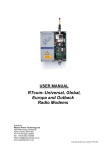
User Manual
RTcomTM-R-O/C
Integrated AMR
3–Output Pulse
Receiver (open collector)
Copyright Radio-Tech Limited 1998-2003
CONTENTS
INTRODUCTION
3
Systems
4
Frequency of operation
6
R.F Path Surveys
7
INSTALLATION
8
GENERAL ARRANGEMENT
RTcomTM-R-O/C
CONNECTIONS
9
10
Pulse outputs
Interfacing with current sink devices
12
Interfacing with current source devices
13
Programming
14
RTcomTM-AMR SOFTWARE
15
CONFIGURATION AND PROGRAMMING
16
COMMUNICATION DATA PACKETS
Pulse Metering
19
Temperature Measurement
20
Humidity and Temperature Measurement
21
Alarm Monitoring
22
Digital Contact Monitoring
23
EMC Conformity
23
2
INTRODUCTION
The RTcomTM-R-OC is a low cost, 3-output pulse receiver with high current open
collector outputs, permitting the delivery of pulses from up to three RTcomTM-P
remote transmitters, which in turn permit connection to water, gas and electricity
meters respectively.
In operation the RTcomTM-R is similar in operation to its big brother the RTcom-8Channel AMR receiver, which can operate with up to 8 single or 4 dual-channel
RTcomTM-P transmitters.
As summary of the key features of the RTcomTM-R are:
Encapsulated, IP68++ water proof design
Integral robust antenna.
Reliable operation down to –20C
12 V dc operation
Optically isolated open collector outputs
PC programmable transmitter addresses into EEPROM memory via
RTcomTM-AMR V5.1 and higher Windows software.
Auto pulse count re-synchronization upon power up, with 100ms
guaranteed minimum pulse width.
Molded in mounting adapter for simple cable tie mounting.
Optional serial output data mode for interfacing to a PC.
3
Receive options:
The receiver outputs can be used to simply generate pulses upon receipt of
transmissions from the programmed transmitter addresses or optionally all three
outputs can be combined to produce a single output in a serial ASCII format which
can be converted into RS232 level by the addition of a simple pull-up resistor.
.
Systems
The RTcomTM-R-OC operation has been tailored to fit within the requirements of the
AMR and sub-metering industries.
The receiver firmware supports the programming and decoding of up to three unique
transmitter addresses that can be selected anywhere from within our 16-million
address range.
Once programmed, each output will respond to transmissions received from its
corresponding pulse transmitter. Initially the first time the receiver receives a
transmission from a registered (one with a programmed address) transmitter, the
receivers counter will assume this to be the initial value and synchronise to it.
Thereafter any change in the cumulative pulse total received will cause the receiver
to generate 100ms duration pulses in a short burst equalling the difference in current
pulse count received and that originally stored.
By following the above strategy, any transmissions lost due to jamming or clashing
will be made up the next time the transmission is received. This ensures that under
no circumstances will pulses be lost.
IMPORTANT: The receiver should be operated from a battery backed power supply.
This is essential as power failure will cause a loss of pulse count. Intentionally if there
is a power failure the receiver will reset its totaliser registers to zero to prevent
overrun in the event of large differentials in the pulse counts.
4
.
Typical Systems
Pulse o/p 1
Pulse Meter (1)
(Water)
Pulse o/p 2
Pulse o/p 3
TM
RTcom -R-OC Pulse
3-output receiver.
Pulse Meter (2)
(Gas)
Pulse Meter (3)
(Electricity)
Pulse metering system with pulse outputs
Pulse Meter (1)
Serial output
levels
RS232
TM
RTcom -R OC434-Receiver
Pulse Meter (3)
Pulse metering system with single serial output
5
For extended distance operation the RTcomTM-AMR repeaters can be used. Normally
a single repeater can be used per system, however cascaded repeater chains can be
created to order.
Frequency of operation
Often there is little to choose from regarding the operating frequency for licence
exempt AMR applications. The RTcomTM-R-OC is available on both of the licence
exempt bands available in Europe, 433-435MHz or 868-870MHz UHF. It is also
available on the FCC-Part 15 band between 904-920MHz. All of these frequency
options match those available on the RTcomTM-P transmitters.
In practice unless there is excessive existing traffic, we always recommend the use of
the 434MHz band as a preference.
A table is given below giving the relative
distances between the three operating bands.
Free Space
Transmission range
Industrial installation
In large buildings
Penetration through
concrete walls
Ability to bend/
diffracts around
obstructions
Antenna size (dipole)
Potential users in
adjacent channels
Transmission
efficiency
For battery operation
Relative cost
UHF
(10mW)
434Mhz
Wide
Band FM
70-250m
UHF
(5mW)
869MHz,
wide Band
FM
50-150m
SHF (3mW)
914.5MHz
FCC Part 15
30-100m
30-200m
20-120m
20-120m
*****
****
****
*****
***
***
17cm
Some
Radio
Amateur
on 433MHz
& Tetra
******
8cm
CT2
****
7.5cm
CT2 &
Mobile
Telephones
Toys, Baby
alarms etc.
****
*
**
**
6
R.F path Surveys & Spectrum scans
The only certain way of determining the suitability of a communication channel is to
conduct a radio path survey and spectrum scan.
The spectrum scan is something normally conducted prior to ordering a system to
ensure the radio band is free from other users. However, as by its nature and AMR
system is a short-range application, interference is extremely rare and the FM
capture effect prevails, (Nearest signal wins). This in most cases obviates the need
for a spectrum survey.
If a confidence scan is required, both the desired and adjacent channels should be
checked for signals. As transmissions may be intermittent it is important to take time
with the scan, stopping for as long as possible on each channel and looking for at
least 15-minutes on the final chosen band.
If there is doubt over the signal reaching the receiver a path survey should be
conducted. Normally our AMR collectors, loggers and hand held devices will work
satisfactorily with a signal level below 100dBm. In free space this equates to a range
of up to 300m. However, within the constraints of a building or a meter pit this can
vary from as little as 10m to 100m. The range ultimately depends upon a combination
of obstructions and the location of the transmitter with respect to metallic objects and
ground level.
7
INSTALLATION
The “rubbish in rubbish” rule applies to installing a successful AMR system. Setting
up effective and efficient practice is essential in order to get the best and consistent
performance out of your RTcomTM-R-OC receiver and -P transmitter/s.
The antenna of the receiver is integrated within the narrow, tubular portion of the
housing. For maximum transmission range the antenna should point upward
(vertically polarised) and should be kept clear of obstructions, in particular metallic
surfaces such as manhole covers, ducting and pipes.
Mounting can be easily achieved using a cable-tie in either the vertical or horizontal
directions as illustrated in the drawing below. Mounting on metallic pipes parallel to
the antenna should be avoided if you are looking to achieve maximum distance.
Finally, the higher the receiver is mounted the better the reception. Every 3m
increase in height normally doubles the operational range.
Full mechanical details of the receiver are given on the following page.
8
9
CONNECTIONS TO THE RTcomTM-R-OC
The RTcomTM-R-OC receiver is normally supplied with a short length of 7–core data
cable, with connections as per table A below.
A clean, 8 to 15V dc supply is required to power the receiver at < 30mA typically.
This should ideally be battery backed to prevent loss of pulse counts in the event of
power failure. The power supply for best performance should be derived from a
source clean of RF interference. Switch mode power supplies are notorious for
generating noise and causing the “it was working OK yesterday” syndrome. This is
due to their interference pattern drifting with temperature and the fact that a CE
badge means nothing to a radio receiver, which is capable of operating at signal
strengths some 60dB below the noise limits of the EMC Directives.
Cable Colour
Function/Description
Red
+12V dc
Black
Ground
Green
GND
Yellow or Orange
RXD (programming input)
White
TXD (programming ACK)
and/or Pulse output 3
Blue
Pulse output 2
Purple
Pulse output 1
The open collector outputs will normally replicate the closing action of a pulse switch,
reed switch, hall effect sensor or transistor driver for terminals designed to operate
with volt free contacts.
10
When the receiving terminal itself requires an external wetting voltage the collectors
should be pulled up to a suitable dc voltage rail via resistors. Normally we
recommend a 4K7 resistor connected to each output. The tolerance and wattage of
this resistor is not important and you should choose a device for ease of mounting.
The diagrammatic equivalent to receiver outputs are given below:
Output 1
Output 2
Output 3
Common
RTcomTM-R-OC
Connections the receiver outputs for pulse operation
11
Interfacing: current sinking to logic
Output 1
Output 2
Output 3
Common
RTcomTM-R-OC
12
Interfacing: current source logic
Output 1
Output 2
Output 3
Common
RTcomTM-R-OC
13
5-12V dc
Programming Interface
TXD to PC for
ACK, Pin 2
RXD, connect to
TX on PC, Pin 3
GND connect to
GND on PC. Pin 5
RTcomTM-R
CONFIGURATION
Configuration is normally once only task performed at or before the installation. The
process of configuration requires knowledge of the transmitter/s address codes and a
copy of our RTcomTM-AMR firmware version 5.1 or above, running on a Windows
based PC. A data cable with a pull 4.7K pull up resistor to the receivers power
supply is also required. This cable can be supplied to order or easily made up
yourself.
14
SOFTWARE INSTALLATION
Software installation is simple. The software is normally supplied on CD ROM and
normally self install upon insertion of the disk. If the machine fails to launch the auto
install click on My Computer and select your CD drive. Clicking on the icon should list
the files on the CD.
Double click on the set up icon, this will launch an install shield. The install shield will
start with text saying “copying files”. This is followed by a dialog box giving you the
opportunity to select the destination drive of choice. Once you are happy with the
destination, please click OK. Then click on the large left hand button to commence
the install. This action will install the programme with one more option box, which
once complete will finish with a final OK dialog box.
15
Commissioning and Running RTcomTM-AMR Software
To run the program use the start button, select programmes and you should see a
programme icon called amr_rtocm.
Double clicking on the icon will run the application.
16
The first task is to select the communications port using the top left click box. Normally this
will be com1.
The date rate should be set to 9600 in order to talk with RTcomTM-R. This is simply selected
by clicking on the respective window.
The desired receiver addresses should be entered into the three top right hand boxes in the
format as written on the transmitters. The mode should also be entered. This is the box that
determines if the unit will be a pulse output or a serial output device.
Enter addresses
Then click Set 3ch Add
17
Enter mode
Finally click set mode
Mode
0
1
2
3
4
5
6-8
9
Function
Receive data from all
addresses, HEX serial
output
Receive data from only
programmed addresses,
HEX serial only
programmed addresses
serial output
Receives all data outputs
in ASCII format
Receives only programmed
addresses and outputs in
ASCII format
Receives all data and
outputs data with full
decode into plain ASCII
text strings
Receives only programmed
address and outputs data
with full decode into plain
ASCII text strings
Not allocated at present
Programmed addresses
output as pulses
All acknowledges will be confirmed with an OK. You are ready to count!
18
Communication Data Packets
The receiver 'listens' to messages being transmitted by the transmitters, decodes
and validates them by checking the CRC. Once validated the packet is transmitted
out of the communications port. The packets vary depending on the type of
transmitters.
Pulse metering:
ID
----ADDRESS------
Status ------Pulse Count-------
Ctr
-----CRC-----
$81
$00
$12
$23
$00
$01
$12
$AA
$34
$??
$??
$81
$01
$22
$00
$00
$00
$00
$01
$38
$??
$??
Where taking line 1 as way of example
Type
81 = pulse transmitter
Address = 001223(Hex)
Status = Low Battery and Firmware Revision Number
Bit 7 set for low battery
Bits 0-3 indicate the firmware revision number
Pulse count = 0112AA(Hex)
70314 (decimal)
CRC = ???? (dependant upon code content)
19
Temperature measurement:
ID
----ADDRESS------
Status -----Temp1-------
----Temp2---
-----CRC-----
$82
$00
$12
$23
$00
$FF
$73
$00
$34
$??
$??
$82
$01
$22
$00
$00
$00
$20
$00
$38
$??
$??
Where taking line 1 as way of example
Type
82 = Temperature transmitter
Address = 001223(Hex)
Status = Low Battery and Firmware Revision Number
Bit 7 set for low battery
Bits 0-3 indicate the firmware revision number
Temp1 = FFC3 where
FF indicates negative temperature
C3 (=195 decimal) translates as (256–195) )/2
= -30.5C (decimal)
Temp2 = 0034 where
00 = +ve temperature
34 = 34(hex)/2 = 26C (decimal)
CRC = ???? (dependant upon code content)
20
Humidity & Temperature Measurement:
ID
----ADDRESS------
Status ----Humidity----
--Temperature --
-----CRC-----
$83
$00
$00
$66
$01
$05
$44
$17
$A9
$FB
$5A
$83
$00
$00
$64
$01
$04
$AC
$18
$C5
$7E
$AD
Humidity conversion:
Humidity (%) = [-0.0000028 x (Measured)2] + [Measured x 0.0405] - 4
Temperature Conversion:
Temperature (deg C) = [Measured x 0.01] - 40
Where taking line 1 as way of example:
Type
83 = Humidity & Temperature transmitter
Address = 000066(Hex)
address 102
Status = Low Battery and Firmware Revision Number
Bit 7 set for low battery
Bits 0-3 indicate the firmware revision number
Humidity (measured) = 0544 (Hex)
1348 (decimal)
Humidity (%) = [-0.0000028 x 1348 x 1348] + [1348 x 0.0405] - 4
= -5.08789 + 54.594 - 4
= 45.50%
Temperature (measured) = 17A9 (Hex)
6057 (decimal)
Temperature (deg C) = [ 6057 x 0.01 ] - 40
= 20.57 deg C
CRC = ???? (dependant upon code content)
21
Alarm Monitoring:
ID
----ADDRESS------
Status ------Pulse Count-------
Ctr
-----CRC-----
$88
$00
$12
$23
$00
$01
$12
$AA
$34
$??
$??
$88
$01
$22
$00
$00
$00
$00
$01
$38
$??
$??
Where taking line 1 as way of example
Type
88 = alarm transmitter
Address = 001223(Hex)
Status = Low Battery and Firmware Revision Number
Bit 7 set for low battery
Bit 4 set for alarm active, clear for ok
Bits 0-3 indicate the firmware revision number
Pulse count = 0112AA(Hex)
CRC = ???? (dependant upon code content )
22
Contact Monitoring:
ID
----ADDRESS------
Status ------Pulse Count-------
Ctr
-----CRC-----
$87
$00
$12
$23
$00
$01
$12
$AA
$34
$??
$??
$87
$01
$22
$00
$00
$00
$00
$01
$38
$??
$??
Where taking line 1 as way of example
Type
87 = Contact transmitter
Address = 001223(Hex)
Status = Low Battery and Firmware Revision Number
Bit 7 set for low battery
Bit 4 set for contact closed, clear for contact open
Bits 0-3 indicate the firmware revision number
Pulse count = 0112AA(Hex)
CRC = ???? (dependant upon code content )
23
Appendix A
A CRC-16 checksum is implemented on every message to detect any bit errors in the message. The
checksum calculation is only used to detect errors but cannot correct them.
The crc generating polynomial used is: x16 + x15 + x2 + 1
CRC Algorithm :
1.
Load a 16 bit register with all 1s’
2.
Exclusive OR the first 8 bit byte with the high order byte of the 16 bit
register, putting the result in the 16 bit register
3.
Shift the 16 bit register one bit to the right
4.
If the bit shifted to the right is a 0
return to step 3
Else
Exclusive OR the generating polynomial 1010 0000 0000 0001 with the
16 bit register
5.
Repeat steps 3 & 4 until 8 shift have been performed
6.
Exclusive OR the next 8 bit byte with the 16 bit register
7.
Repeat step 3 through 6 until all bytes of the message have been exclusive
OR’d with the 16 bit register and shifted 8 times
8.
The contents of the 16 bit register are the 2 byte CRC error check and is
added to the message msb first.
24
Visual Basic CRC Routine
' MODBUS CRC Algorithm
Function Tcrcgen()
Hicrc = &HFF
Locrc = &HFF
' Put data received into array
For i% = 1 To Len(Outstring)
Outarray(i%) = Mid$(Outstring, i%, 1)
Hicrc = Hicrc Xor Asc(Outarray(i%))
For Q% = 1 To 8
Carry = Hicrc And &H1
' Below is Hicrc=((Hicrc shr 1)&$7F) OR ((Locrc & $01) shl 7)
Hicrc = Hicrc \ 2
If (Locrc And &H1) <> 0 Then
Hicrc = Hicrc Or &H80
End If
' Below is Locrc=(Locrc shr 1) and $7Fh
Locrc = Locrc \ 2
If Carry <> 0 Then
Locrc = Locrc Xor &HA0
Hicrc = Hicrc Xor &H1
End If
Next Q%
Next i%
End Function
25
' MODBUS CRC Algorithm
Function Rcrcgen()
Hicrc = &HFF
Locrc = &HFF
' Put data received into array
For i% = 1 To (Numchars - 2)
' Ignore header and crc bytes
Hicrc = Hicrc Xor Inarray(i%)
For Q% = 1 To 8
Carry = Hicrc And &H1
' Below is Hicrc=((Hicrc shr 1)&$7F) OR ((Locrc & $01) shl 7)
Hicrc = Hicrc \ 2
If (Locrc And &H1) <> 0 Then
Hicrc = Hicrc Or &H80
End If
' Below is Locrc=(Locrc shr 1) and $7Fh
Locrc = Locrc \ 2
If Carry <> 0 Then
Locrc = Locrc Xor &HA0
Hicrc = Hicrc Xor &H1
End If
Next Q%
Next i%
If ((Inarray(Numchars - 1)) = Hicrc) And ((Inarray(Numchars)) = Locrc) Then
crcpass = True
Else
crcpass = False
End If
End Function
Copyright Radio-Tech Limited 1998-2003
All information is given in good faith. Equipment should not be used where failure could result in loss of life or damage
to the environment. No losses can be accepted for errors or omissions contained in this document. It is the
responsibility of the user to confirm licensing and other legal issues.
Revision, Issue 1
Distributor:
Wessex Power Technology Ltd
189 Ashley Road, Parkstone
Poole, Dorset, BH14 9DL
Tel: +44 (0)1202 723000
Fax: +44 (0)1202 723400
Email: [email protected]
www.wessexpower.co.uk
26