1
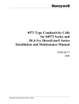
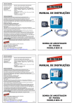
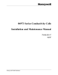
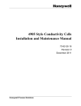
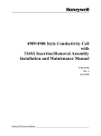
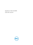
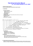
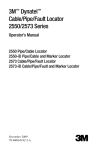
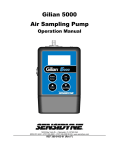
4905 Style Conductivity Cells for 04905
Series and DL4-5xx DirectLine® Series
Installation and Maintenance Manual
70-82-25-18
Rev. 3
6/04
Copyright, Notices, and Trademarks
Printed in U.S.A. – © Copyright 2004 by Honeywell Inc.
Revision 3 – 6/04
While this information is presented in good faith and believed to be
accurate, Honeywell disclaims the implied warranties of
merchantability and fitness for a particular purpose and makes no
express warranties except as may be stated in its written
agreement with and for its customer.
In no event is Honeywell liable to anyone for any indirect, special or
consequential damages. The information and specifications in this
document are subject to change without notice.
Honeywell
Industrial Measurement and Control
1100 Virginia Drive
Fort Washington PA 19034
ii
4905 Series Conductivity Cells – Installation and Maintenance
6/04
About This Document
Abstract
This document is intended to support the installation, operation and maintenance of the 4905 Series of
Conductivity Cells.
Revision Notes
The following list provides notes concerning all revisions of this document.
Rev. ID
Date
Notes
0
12/96
This document is the initial Honeywell release of the L&N manual p/n 177667
Rev. M2. There has been no significant changes made to this manual. The
format has been changed to reflect the Honeywell layout.
1
6/99
Edits done to add new Model Selection Guide information and to correct
some errors in the text.
2
6/03
Removed obsolete info, added DL4000 details.
References
Honeywell Documents
The following list identifies all Honeywell documents that may be sources of reference for the material
discussed in this publication.
Document Title
ID #
9782 Series Conductivity/Resistivity Analyzer/Controller Operator’s Manual
70-82-25-74
APT2000CC Transmitter User Manual
70-82-25-95
APT4000CC Analyzer User Manual
70-82-25-104
DirectLine Module for Conductivity User Manual
70-82-25-112
Contacts
The following list identifies important contacts within Honeywell.
Organization
Telephone
Address
Honeywell Tech support
1-800-423-9883 Voice
1100 Virginia Drive
Fort Washington, PA 19034
6/04
4905 Series Conductivity Cells – Installation and Maintenance
iii
Contents
1.
INTRODUCTION ................................................................................................... 1
1.1
2.
SPECIFICATIONS AND MODEL SELECTION GUIDE ........................................ 3
2.1
Specifications ................................................................................................................................. 3
2.2
Model Selection Guides ................................................................................................................. 4
3.
INSTALLATION .................................................................................................... 7
3.1
Overview ........................................................................................................................................ 7
3.2
Types of Mounting ......................................................................................................................... 7
3.3
Flow-Type Mounting ..................................................................................................................... 8
3.4
Immersion-Type Mounting for 04905 Series Cells........................................................................ 8
3.5
Insertion-Type Mounting ............................................................................................................... 9
3.6
Electrical Connections.................................................................................................................. 11
4.
iv
Overview ........................................................................................................................................ 1
MAINTENANCE .................................................................................................. 17
4.1
Introduction .................................................................................................................................. 17
4.2
To Clean The Cell ........................................................................................................................ 17
4.3
To Check Conductivity System.................................................................................................... 17
4.4
Replacement Parts and Accessories ............................................................................................. 18
4905 Series Conductivity Cells – Installation and Maintenance
6/04
Figures
Figure 1-1 4905 Type Conductivity Cell Mounted in a 1-1/4” Schedule 80 Tee Using an Adapter
Bushing ________________________________________________________________________ 1
Figure 3-1 Types of Mountings for 4905 Type Conductivity Cells ______________________________ 7
Figure 3-2 Typical Conductivity Measuring Installation ______________________________________ 8
Figure 3-3 Dimension Drawing for 276127 Flow Housing ___________________________________ 10
Figure 3-4 Mounting Dimensions for 04905 Series and DL4-5xx Series Cells ____________________ 11
Figure 3-5 Mounting Dimensions for 04905 Series with Junction Box Head (Not available on DL4-5XX
DirectLine Cells) ________________________________________________________________ 11
Figure 3-6 4905 Series Cell with Junction Box Head Connected to 9782 Conductivity/Resistivity
Analyzer_______________________________________________________________________ 12
Figure 3-7 04905 Series Cells with 7 or 20 Foot Leads Connected to 9782 Conductivity/Resistivity
Analyzer or Connected to Junction Box ______________________________________________ 13
Figure 3-8 04905 series cells with 20’ leads connected to an APT4000 _________________________ 14
Figure 3-9 04905 series cells with or 20’ leads connected to an APT2000_______________________ 14
Figure 3-10 Integral DirectLine Mounting with DL4-5xx ____________________________________ 15
Figure 3-11 Remote DirectLine DL4-5xx series with 20’ lead connected to a DL423 Modbule (through
the use of the Remote Connector Assembly)___________________________________________ 16
6/04
4905 Series Conductivity Cells – Installation and Maintenance
v
vi
4905 Series Conductivity Cells – Installation and Maintenance
6/04
Introduction
1. Introduction
1.1 Overview
These cells form the sensing network for industrial analyzers and transmitters designed to make continuous
measurements of electrolytic conductivity. The cells are primarily suited to measurements in effluents of
ion-exchangers and distillation columns; but appropriate constants are provided for many other
applications, including measurements in micro-electronic component washing and plating-rinse effluents.
Universal in mounting, any of the cells can be arranged for immersion (except DL4000 Series), insertion
(1” NPT) or flow type sampling. The latter can be achieved by use of a CPVC flow housing, a 1” pipe tee
(schedule 40), or 1-1/4” plastic tee (schedule 80) installed in a process line or bypass line as pictured in
Figure 1-1.
Cell Assembly
Adapter Bushing
Schedule 80
1-1/4" Pipe Tee
Guard Tube
on Cell
a/n 23381
Figure 1-1 4905 Type Conductivity Cell Mounted in a 1-1/4”
Schedule 80 Tee Using an Adapter Bushing
ATTENTION
Please note that specific parameters of your process may prohibit the use of nickel elements. For example,
use a platinum-element cell if the cell will measure or be exposed to regeneration acids or bases.
6/04
4905 Series Conductivity Cells – Installation and Maintenance
1
4905 Series Conductivity Cells Installation and Maintenance Manual
The cell constant is selected according to the range of the measuring instrument used and the solution
measured. In general, a high-constant cell is used for solutions having low electrical resistance (high
conductivity) and a low-constant cell is used for solutions having high electrical resistance (low
conductivity). The DL4-5xx Series of 4905 style cells used with the DirectLine Module (DL423 Series)
can be specified for either integral or remote mounting of the module. The integral mount cell has a PC
board connector so the DirectLine module mounts directly on the cell. Cells for remote mounting of the
DirectLine module have a 20’ cable that is an integral part (potted) of the cell. Automatic Temperature
Compensation (ATC) during the measurement is provided by a built-in temperature sensing network
located near the cross-channel or guard-tube holes.
The cells are molded from Polyethersulfone (PES) which is resistant to most corrosive chemicals over a
wide range of temperatures. (A common exception is chlorinated hydrocarbons.) Sample solutions come
into contact only with the above plastic and the platinum or nickel electrode surface. Any cell can be
supplied with either electrode material.
2
4905 Series Conductivity Cells – Installation and Maintenance
6/04
Specifications and Model Selection Guide
2. Specifications and Model Selection Guide
2.1 Specifications
Cell Constant -
04905 Series: 0.01, 0.1, 1.0, 10, and 50 as specified.
DL4-5xx: 0.1, 10, 50 as specified
Electrode Material -
Nickel or platinum as specified.
Maximum Pressure Limit -
250 psig (1724 kPa) @ 140°C (284°F).
Maximum Continuous Temperature Limit - 140°C (284°F)
Mounting
Insertion-
1” NPT male, Schedule 40.
Flow Chamber -
Inlet - 3/4” NPT Male. Outlet: 3/4” NPT Female.
Insertion Depth -
5” to 7” (127 to 178 mm) depending on cell constant.
Overall Length -
Approximately 6 to 8” (152 to 203 mm) or 10 to 12-1/4”
(254 to 311 mm) if universal head is used.
Materials of Construction
(Wetted Parts) -
Cell body: PES (Polyethersulfone).
Electrodes: nickel or platinum.
Leadwire-
Tefzel-covered 18 gage cable, 0.177” (4.55 mm) OD at
lengths listed.
Weight -
Approximately 1 lb (0.45 kg) or 3 lb (1.35 kg) if universal
head is used.
Specifications for 276127 Flow Chamber
6/04
Max. Flow -
2 gpm @ 40 psig and atmospheric discharge.
Max. Pressure -
200 psig at 25°C.
Max. Temperature -
140°C (284°F) at atmospheric pressure.
Dimensions -
1-1/2” (3.8 cm) octagon x 8-3/4” (22.2 cm) long. Sample
inlet: 3/4” NPT male. Sample outlet: 3/4” NPT female.
Cell inlet: 1” NPT female.
Material -
Polyethersulfone (PES)
4905 Series Conductivity Cells – Installation and Maintenance
3
4905 Series Conductivity Cells Installation and Maintenance Manual
2.2 Model Selection Guides
4905 Series for use with 9782 Series or APT Series
Instructions
Consult Steps to Selecting Appropriate Conductivity Instrumentation and Cells before
making selections below. (Section 2 INTRO)
Select the desired key number. The arrow to the right marks the selection available.
Make one selection from each Table using the colum below the proper arrow.
A dot denotes unrestricted availability.
Key Number
_____
I
-
___
II
-
__
III
-
___ -
IV
__
V
-
___
KEY NUMBER
Description
04905 Conductivity Cell
VI
-
___
Selection
04905
TABLE I - CELL CONSTANT
0.01
0.1
1
10
50
001
X01
XX1
X10
X50
TABLE II - ELECTRODE MATERIAL
(Note 1)
Nickel
(Note 1)
Platinum
33
44
TABLE III - AUTOMATIC TEMPERATURE COMPENSATION
For APT2000/4000CC, 9782C, or 7082 Only
333
TABLE IV - Leadwire Length
20 ft. (6,10 meters) Leadwire
Leadwire Length
Universal Head (Aluminum)
20
X1
TABLE V - Special Insertion Lengths
None
Special Insertion
4.4 in. (111,76 mm) extra
Length
8.8 in. (223,52 mm) extra
4
Availability
(Note 2)
c
000
910
920
4905 Series Conductivity Cells – Installation and Maintenance
6/04
Specifications and Model Selection Guide
TABLE VI - OPTIONS
Tagging
None
Linen
Stainless Steel
0_ _
L_ _
S_ _
No
Certificate of Calibration
Yes
& Conformance
_0_
_1_
_ _0
Future
Note 1: Platinum is used in acid and base applications; Nickel is used in all others
Note 2: If shorter length is required, cut to length, skin and tin ends.
RESTRICTIONS
Restriction
Letter
c
Available Only With
Table
III
Selection
Not Available With
Table
Selection
For 9782/7082 and
APT2000/4000CC
Analyzers Only
DL4000 Series for use with DirectLine Sensor Modules
Instructions
Select the desired key number. The arrow to the right marks the selection available.
Make the desired selections from Table I using the column below the proper arrow.
A dot ( ) denotes availability. No ( ) dot denotes not available.
II
I
III
Key Number
____
___
- ___ - ___ -
Key Number - Mounting/Electrode Only (Specify DL423 separately)
Selection
Contacting Conductivity Probes/Mountings for use with DL423
DL4
TABLE I - Mounting Type, Construction, Cell Constant, DirectLine Connection
Material of
DirectLine
Internal
Cell/Mounting Type Construction Cell Constant Connection
EEPROM
Titanium
0.1
Integral
High Purity In-line
Graphite
10
Yes
Titanium
0.1
(4973-style)
1
Remote
Graphite
10
301
302
311
312
Not available for 4905 Style Conductivity Cells
6/04
4905 Series Conductivity Cells – Installation and Maintenance
Availability
5
4905 Series Conductivity Cells Installation and Maintenance Manual
TABLE I - Mounting Type, Construction, Cell Constant, DirectLine Connection (continued)
Internal
Material of
Cell
Construction DirectLine
Note 2
EEPROM Selection
Cell/Mounting Type
Constant Connection
0.1
Nickel
501
0.1
Platinum
502
10
Nickel
503
Integral
Yes
10
Platinum
504
50
Nickel
505
General Purpose
506
Platinum
50
(4905-style)
0.1
511
Nickel
512
Platinum
0.1
513
Nickel
10
1
Yes
Remote
10
Platinum
514
50
Nickel
515
516
50
Platinum
0.1
Nickel
911
Stainless Steel
0.1
Platinum
912
Insertion/Removal
10
Nickel
913
1
Yes
Remote
10
Platinum
914
Assembly With Cell
Nickel
915
50
(4909-style)
Platinum
916
50
811
Nickel
0.1
Stainless Steel
0.1
812
Platinum
10
Insertion/Removal
813
Nickel
1
Yes
Remote
10
814
Platinum
Replacement Cell
50
815
Nickel
(4908-style)
50
816
Platinum
Availability
Not available for 4905 Style Conductivity Cells
Not available for 4905 Style Conductivity Cells
Notes:
1. Remote conductivity cells are supplied with a integral 6,1m (20 ft.) sensor cable which must be
wired to the DL423 remote connector (supplied with DL423 Sensor Module).
2. Platinum is used in acid and base applications; Nickel in all others
TABLE II - Special Cell Constructions
Cell Type
Special Construction
ALL
None
Extra 4.4" of cell length
4905
316 SS Support Tube
4909/4908
000
440
316
TABLE III - Options
Tagging
Calibration
Certificate
6
None
Linen Customer I.D. Tag - 3 lines w/22 characters/line
Stainless Steel Customer I.D. Tag
-3 lines with 22 characters per line
None
Calibration certificate to be supplied w/shipment
00 _ _
LT _ _
SS _ _
_ _ 00
_ _ 10
4905 Series Conductivity Cells – Installation and Maintenance
6/04
Installation
3. Installation
3.1 Overview
The conductivity cell is secured permanently to the 1” N.P.T. bushing which is used for all types of
mountings. The three different types of mountings are illustrated in Figure 3-1. Although the physical
appearance of the various cells is the same (except for length), the cell construction differs according to the
constant. On the 10, 25 and 50 constant cells, the electrodes are short tubes located midway inside the two
parallel tubular channels that run lengthwise through the cell, and are open to the sample at both ends of
the cell. The channels are larger on the 25 constant cell and they are elliptical on the 5 and 10 constant
cell. The 1, 0.1, and 0.01 constant cells have a removable cell guard which is screwed onto the cell body to
protect the electrode surfaces. Electrodes are three disks on the 1 constant cell, parallel plates on the 0.1
constant cell, and wire wound on the cell body on the 0.01 constant cell. Cells must be used with the guard
in place or the cell constant may differ from that specified.
Most of the auxiliary parts which enable the user to achieve the various types of mounting are readily
obtained from local suppliers. For an immersion mounting with 04905 Series cells, only the appropriate
length of 1/2 inch pipe (e.g., CPCV) and if desired, a 1/2 inch end coupling is needed. For an in-line flow
mounting, only a 1” schedule 40 tee is required. The basic cell can be converted to a flow cell for either
bypass or in-line arrangements by use of the PES flow-cell housing (Honeywell Part 276127) shown in
Figure 3-1 and Figure 3-3. However, the temperature and pressure specifications listed for this flow
chamber under Specifications apply.
ATTENTION
The DL4-5xx Series DirectLine cells have a EEPROM device for automatic download of cell constant and
cell calibration factor. During installation proper ESD protection is required so the memory device is not
damaged.
3.2 Types of Mounting
The three types of mounting; Flow, Immersion and Insertion, are illustrated in Figure 3-1. Mounting
dimensions for each type of cell assembly are given in Figure 3-3, Figure 3-4, and Figure 3-5.
Insertion
Type
Immersion Type
(Pipe extension
and coupling
not supplied)
Not available
with DirectLine
cells DL4-5XX
series.
Flow Type
Using Plastic
Flow Housing
(Honeywell p/n 276127)
a/n23382a
Figure 3-1 Types of Mountings for 4905 Type Conductivity Cells
6/04
4905 Series Conductivity Cells – Installation and Maintenance
7
4905 Series Conductivity Cells Installation and Maintenance Manual
3.3 Flow-Type Mounting
The cross-channel or guard-tube hole in the cell must always be covered by the solution and the solution
level must be 1-1/2 inches above these holes. When mounting the cell in a pipe tee such as shown in
Figure 3-2, have the solution enter the tee from below and exit to the side. As shown, the guard-tube hole
is in line with the horizontal pipe run. However, if it is possible that the pipe line will not be full at all
times, locate the hole just below the exit pipe to insure flooding of the cell under all conditions. As shown
in Figure 3-2, always locate the cell on the pressure side, not the vacuum side of the pump. The flow-cellhousing, an accessory part having 3/4” male inlet and female outlet threads, can be used for an in-line
measurement or in a bypass line as shown in Figure 3-2, depending upon the flow volume or pipe size.
Adapter bushings are available to convert inlet and outlet fittings to 1/4” female threads. See Section 4.4 .
The cell must be covered by the solution at all times. Therefore, make certain the lowest solution head is
higher than the cell location. See that an air bubble does not prevent the cell from filling properly.
Flow-cell housing can be used “in-line” only if a maximum flow of 2 gallons per minute can be tolerated.
To avoid cracking the 276127 flow-cell housing, use Teflon tape on cell threads and tighten cell only
enough to prevent leakage.
To install, tighten the cell into a 1” schedule 40 pipe tee. If the flow-cell housing is used, assemble the cell
and housing and install it in the process flow line or in a bypass line.
Process
Preferred
Cell Locations
Cooler
15"
(381mm)
Pump
a/n 23383
Figure 3-2 Typical Conductivity Measuring Installation
3.4 Immersion-Type Mounting for 04905 Series Cells
Does not apply to DL4-5xx Series Cells. The cell must be immersed to a level above the cross-channel or
guard tube hole and must be immersed to 1-1/2 inches above this hole if an integral compensator is used.
For most immersion applications, a 1/2” support pipe, preferably CPCV must be threaded into the cell
bushing, using Teflon tape to seal the threads, thus permitting adequate immersion. Unless this pipe
extension is used, do not immerse the top of the bushing. To insured that a representative sample is
measured at all times, the solution must circulate through the channels. In quiescent solutions, provide
sufficient agitation.
To install the cell, determine the length of 1/2” pipe required to give the immersion needed to keep the cell
completely immersed at all times. Up to six feet of pipe can be used for the standard cell having seven feet
of cable. Remove the small bushing at the top of the cell, slide it off the cable, and replace it with the 1/2inch pipe. At the top of the pipe slide a pipe coupling and the small bushing back over the leadwire as
shown in Fig. 3-1, or install a junction box to terminate the pipe.
8
4905 Series Conductivity Cells – Installation and Maintenance
6/04
Installation
3.5 Insertion-Type Mounting
The cell can be inserted into a 1” N.P.T. threaded opening, but it is imperative that the tank or chamber be
full under all process conditions. Make certain the liquid head is above the cell location. A vertical
insertion (from above) or a horizontal insertion can be used. To install, simply tighten the cell into a 1”
N.P.T. threaded opening (using a Teflon thread compound such as Teflon tape) so that the entire electrode
is immersed in the measured solution. Allow at least 1/2-inch clearance beyond the end of the cell. In
applications where vertical mounting is required, avoid a position with the cell channels pointed up, as this
will permit solution to flow down into the open end of the cell and may result in clogging by solids settling
in the cell channels. See Figure 3-2.
6/04
4905 Series Conductivity Cells – Installation and Maintenance
9
4905 Series Conductivity Cells Installation and Maintenance Manual
Flow Out
1 1/2"
(38mm)
Octagon
1 1/2"
(38mm)
3/4" NPT
Flow Chamber
1 1/2"
(38mm)
Octagon
3/4" NPT
Flow In
IN
CELL
1 1/2"
(38mm)
8 3/4"
(222mm)
13 1/4"
(337mm)
1" Fitting
Allow 7 3/4" (197mm) for removal of cell
RED
Temp.
Comp.
Cell
Shunt
Comp.
RED
Temp.
Comp.
WHITE
WHITE
BLACK
Linear Micromho,
Resistivity, or
Concentration Ranges
Series
Comp.
Cell
WHITE
BLACK
Cell
BLACK
Non-Linear
Micromho Ranges
Without Temp.
Compensation
RED
GREEN
WHITE
Cell
BLACK
Linear Ranges
(Table III = 333)
Cell Wiring
NOTES:
1. Mount cell and flow chamber horizontally as shown above with flow exit "up to eliminate possible air gap around cell body.
2. If cell and flow chamber must be mounted vertically, attach a short length of tubing to flow exit as shown below and form
a trap to ensure filling of flow chamber, especially at low flow.
CELL
2" min.
(51mm)
IN
a/n 23384
Figure 3-3 Dimension Drawing for 276127 Flow Housing
10
4905 Series Conductivity Cells – Installation and Maintenance
6/04
Installation
"X"
See Table
1.687"
(42.8mm)
Cell
Constant X" Approx.
001
0.1
1
5
10
20
25
50
5.4"
5.4"
5.4"
4.5"
mm
138
138
138
114
146
5.8"
6.0"
152
175
175
6.9"
6.9
1" NPT
0.940"
(24mm) Dia
Cell cable is approx. 0.250"
(6.4 mm) O.D. max. with 3 or 4
conductors of #18 AWG wire.
1.5"
(38mm) Octagon
a/n23385
Figure 3-4 Mounting Dimensions for 04905 Series and DL4-5xx Series Cells
"X"
See Table
Cell
constant X" Approx.
001
5.4"
5.4"
0.1
1
5.4"
5
4.5"
10
5.8"
20
6.0"
25
6.9"
50
6.9"
5.5"
(140mm)
mm
138
138
138
114
146
152
175
175
Fou Point Terminal
Four
Board for lead wire
connections. Each #6-32
screw terminal will
accomodate one
#12 or smaller
small AWG wire
3"
(76mm)
1" NPT
0.940"
(24mm) Dia
1.5"
(38mm) Octagon
¾”female NPT for user's
flexible electrical conduit
connection. For insertion or
removal of cell, disconnect
conduit connections.
NOTE: For existing users with conduit, a ¾” x ½” adapter bushing will be required to use existing conduit.
Figure 3-5 Mounting Dimensions for 04905 Series with Junction Box Head
(Not available on DL4-5XX DirectLine Cells)
3.6 Electrical Connections
The detailed terminal-board connections for the analyzer or transmitter are given in the appropriate
directions furnished with the measuring instrument. See Figure 3-6 and Figure 3-7 for connections to the
9782 Analyzer. See Figure 3-8 and Figure 3-9 for connections to the APT Series. See Figure 3-10 and
Figure 3-11 for connections to the DirectLine Modules.
To avoid the possibility of ac pickup in the cell leads, separate them from all ac line-voltage wiring or run
them in a separate grounded conduit.
6/04
4905 Series Conductivity Cells – Installation and Maintenance
11
4905 Series Conductivity Cells Installation and Maintenance Manual
FivePoint Terminal Board.
EachTerminal Will Accept
#16GageMax. Wire
SH
G
1000 max.
1000ft.
Temp.
Comp.
RED
BB
B
GREEN DDD
Cell
G
W
K
W
A
D
DDD
BB
B
C
Note2
C
WHITE CC
BLACK AAA
Internal Cell Assembly
bly
Configuration
Note3
R
R
CCC
AAA
Viewof JunctionBoxHead
withCapRemoved
CoaxCable
Shield
K
(Note5)
#2Temp
Compensator
#1Temp
Compensator
Cell 2(Note5)
Electrodes
Cell 1
Electrodes
Note1
Conductivity/Resistivity
Analyzer
GND
Analyzer Input Connections
NOTES:
1. For pure water samples in non-conductive (plastic, glass, etc.) piping, ground the black cell
electrode lead near the cell.
Alternatively, connect to the 7082 ground screw as shown dotted. Do not ground 10, 25, or
50 constant cells.
2. 9782C – S0 – xx – Exxxx – BD (Standard Range Only)
Use 18 gage minimum coaxial cable type RG6/U connecting shield to terminal “SH” only.
3. 9782C – S0 – xx – EOOOO – BD
For cable runs of up to 500 ft., use 18 gage minimum, three conductor cable
For cable runs of 500 - 1000ft., use 16 gage minimum, three conductor cable
9782C – W0 – xx – EOOOO – BD [coax and shield (SH) not used]
For cable runs of up to 500 ft., use 18 gage minimum, three conductor cable
For cable runs of 500 - 1000ft., use 16 gage minimum, three conductor cable
4. Cell to analyzer cables are considered low level. Run separate from high level wiring.
5. If 2 cells are to be applied, the same wiring guidelines are applied to Cell 2 as are followed
for Cell 1.
Figure 3-6 4905 Series Cell with Junction Box Head
Connected to 9782 Conductivity/Resistivity Analyzer
12
4905 Series Conductivity Cells – Installation and Maintenance
6/04
Installation
Five Point Terminal Board.
Each Terminal Will Accept
#16 Gage Max. Wire
SH
G
20 ft. max.
R
G
RED
Temp.
Comp.
Red
Green
Black
White
GREEN
WHITE
Cell
I
-
II
-
III
IV
333 - X1
II
III
I
4973
4974
-
4908
4909
-
W
K
W
BLACK
K
Cell cable is approx. 0.250"
(6.4mm) O.D. max. with 4
conductors of #18 AWG
wire, 7 or 20 foot length.
Cell Assembly Connections
4905
R
V VI
IV
V
III
IV
333 - X1
V
#1 Temp
Compensator
Cell 2 (Note 5)
Electrodes
Cell 1
Electrodes
Note 1
Conductivity/Resistivity
Analyzer
Analyzer Input Connections
Di re c t Ce l l to Ana l yze r Ins t al l a t i o n
GND
333 - X1 I
II
-
VI VII
20 ft. max.
SH
1000 ft. max.
G
Note 3
Red
Green
Black
White
I
-
II
-
III
IV
333 - X1
II
III
I
4973
4974
-
4908
4909
-
R
R
G
G
K
W
Junction Box
Cell Assembly Connections
4905
(Note 5)
#2 Temp
Compensator
V VI
R
W
Note 2
Coax Cable
Shield
K
W
K
Ce l l t o Ana l yz e r T hro ugh J unc t i o n Bo x
IV
V
III
IV
333 - X1
V
Note 3
(Note 5)
#2 Temp
Compensator
#1 Temp
Compensator
(Note 5)
Cell 2
Electrodes
Cell 1
Electrodes
Note 1
333 - X1 I
II
-
VI VII
Conductivity/Resistivity
Analyzer
GND
Analyzer Input Connections
NOTES:
1. For pure water samples in non-conductive (plastic, glass, etc.) piping, ground the black cell electrode lead near the cell.
Alternatively, connect to the 7082 ground screw as shown dotted. Do not ground 10, 25, or 50 constant cells.
2. 9782C - S0 (only)
Use 22 gage minimum coaxial cable type RG59/U connecting shield to terminal "SH" only.
3. 9782C - S0
For cable runs of up to 500 ft., use: 18 gage minimum, three conductor cable.
For cbale runs of 500 - 1000 ft., use: 16 gage minimum, three conductor cable.
9782C - W0 [coax and shield (SH) not used]
For cable runs of up to 500 ft., use: 18 gage minimum, four conductor cable.
For cable runs of 500 - 1000 ft., use: 16 gage minimum, four conductor cable.
4. Cell to analyzer cables are considered low level. Run seperate from high level wiring.
5. If 2 Cells are to be applied, the same guidelines are applied to Cell 2 as wereused for Cell 1.
a/n 23346
Figure 3-7 04905 Series Cells with 7 or 20 Foot Leads Connected to 9782
Conductivity/Resistivity Analyzer or Connected to Junction Box
6/04
4905 Series Conductivity Cells – Installation and Maintenance
13
4905 Series Conductivity Cells Installation and Maintenance Manual
Figure 3-8 04905 series cells with 20’ leads connected to an APT4000
Figure 3-9 04905 series cells with or 20’ leads connected to an APT2000
14
4905 Series Conductivity Cells – Installation and Maintenance
6/04
Installation
Electronics
Module
Locking Screw in
Rear of Housing
Cell
Figure 3-10 Integral DirectLine Mounting with DL4-5xx
6/04
4905 Series Conductivity Cells – Installation and Maintenance
15
4905 Series Conductivity Cells Installation and Maintenance Manual
Electronics Module
Conductivity Cell Remote Connector
1
2
3
4
5
6
Black Protective
Sleeve
(do not remove)
Red
Black
Green
White
Blue
Brown
6
1
5
2
4
3
Cover
Strain Relief
Compression Cap
Remote Wiring Cable
Cell
Remote Electronics Module
for Conductivity Cells
Figure 3-11 Remote DirectLine DL4-5xx series with 20’ lead connected to a DL423 Modbule
(through the use of the Remote Connector Assembly)
16
4905 Series Conductivity Cells – Installation and Maintenance
6/04
Maintenance
4. Maintenance
4.1 Introduction
If abnormal readings occur, this may indicate poor response because the cell is not filled with process
solution. Check the cell installation. Note that a grayish dull surface on the cell plastic (normally glassy)
can result from exposure to temperatures above 140°C.
The only maintenance which may be required is occasional cleaning in certain applications.
Cell constants 0.01, 0.1, and 1 cannot be used if solution resistance measures less than 1000 ohms unless
the cell is platinized in accordance with Section 5.
4.2 To Clean The Cell
The cell will require cleaning if sludge, slime, etc., accumulates in the flow channels. Since the materials
of construction are chemically inert, chemical agents may be used and are recommended for cleaning the
cells. The particular cleaning agent used must be selected according to the type of contamination to which
the cell is exposed.
CAUTION
The cell housing is PES (Polyethersulfone). DO NOT clean with acetone, chloroform, toluene, benzene, or any
other chlorinated hydrocarbon.
In general, soap and hot water are effective and adequate. If necessary, a soft bristle brush of about 1/4”
diameter may be used to clean out the tubular channels of the 10, 25, and 50 constant cells. Do not scratch
the electrode surfaces. Be especially careful not to bend the electrode plates of the 0.1 constant cell. Rinse
the cell thoroughly in tap water and then in distilled water if available.
4.3 To Check Conductivity System
To check the conductivity system comprising conductivity cell, leadwire, and measuring instrument, the
user may desire to make a measurement in a reference solution of known conductivity. Control the
temperature only within limits consistent with the desired accuracy. The 25°C temperature value is
suggested. The solutions may be prepared in the presence of air. The solution must fill the cell during
measurement.
For optimum accuracy in acid measurements above 5% concentration, use the “Calibration Trim” function
available in the conductivity instrument. See the 9782, APT 2000/4000 or DirectLine Model DL423
manuals for details on the trim function.
To check the constant of a cell, use a second cell having the same constant and compare the reading of one
against the other.
If the 04905 Series conductivity cell model number contains ‘333’, the normal resistance of the
temperature sensor as measured across the red (B) and green (D) leads is 8550 ohms at 25°C.
To check the electrode insullation, connect an ohmmeter across the black (A) and white (C) leads. With a
dry and clean cell, the resistance should be greater than 50 megohms.
6/04
4905 Series Conductivity Cells – Installation and Maintenance
17
4905 Series Conductivity Cells Installation and Maintenance Manual
4.4 Replacement Parts and Accessories
Description
Part Number
Cell Guard Tube (1, 0.1, and 0.01 constants only)
065632
Leadwire bushing for 04905 Series Cells
050366
Flow Cell Housing, PES
276127
1 1/4” to 1” Bushing to adapt cell to 1 1/4” Schedule 80 pipe tee, PVDC
276142
Cell Extension Leadwire Table III other than 333
Three conductor PVC 18 gage (105°C max, Belden 9493)
834059
Three conductor Tefzel 18 gage (140°C max)
834086
Junction Box
316260
9782 Standard Ranges
Up to 500 ft.
Three conductor, 18 gage cable (Belden 9494)
834059
Coax Cable (Belden 9259) – 22 AWG
Coax Cable (Belden 9290) – 18 AWG
835024
------
Up to 1000 ft.
Four conductor (3 used), 16 gage cable (Belden 9494)
834055
Coax Cable (Belden 9259) – 22 AWG
Coax Cable (Belden 9290) – 18 AWG
835024
------
9782 Wide Ranges
Up to 500 ft. - Four conductor, 18 gage
834052
Up to 1000 ft. - Four conductor, 16 gage
834055
DirectLine DL423
Remote Connector
18
51500768-004
4905 Series Conductivity Cells – Installation and Maintenance
6/04
Industrial Measurement and Control
Honeywell, Inc.
1100 Virginia Drive
Fort Washington, Pennsylvania 19034
70-82-25-18 0604 Printed in USA
www.honeywell.com/imc