1
“I declare that I have read this work and in my opinion this
work is adequate in terms of scope and quality for the
purpose of awarding a Bachelor’s of Engineering (Electrical Control & Instrumentation)”
Signature
: ……………………………
Name of Supervisor : Assoc.Prof..Dr. Yahaya Md Sam
Date
: ……………………………
PSZ 19:16 (Pind. 1/07)
UNIVERSITI TEKNOLOGI MALAYSIA
DECLARATION OF THESIS / UNDERGRADUATE PROJECT REPORT AND COPYRIGHT
Author’s full name : MOHD HAFIZIE BIN SUDIN
Date of Birth
: 27/01/1991
Title
: SUSTAINABLE HOME TEMPERATURE MONITORING SYSTEM (SHTC) USING
MICROCONTROLLER
Academic Session : 2013/2014
I declare that this thesis is classified as:
CONFIDENTIAL
(Contains confidential information under the Official Secret Act
1972)*
RESTRICTED
(Contains restricted information as
organization where research was done)*
OPEN ACCESS
I agree that my thesis to be published as online open access
(full text)
specified
by
the
I acknowledged that Universiti Teknologi Malaysia reserves the right as follows:
1. The thesis is the property of Universiti Teknologi Malaysia
2. The Library of Universiti Teknologi Malaysia has the right to make copies for the
purpose of research only.
3. The Library has the right to make copies of the thesis for academic exchange.
Certified by:
SIGNATURE
910127-03-5917
(NEW IC NO/PASSPORT)
Date:
NOTES:
*
JUNE 2014
SIGNATURE OF SUPERVISOR
ASSOC PROF DR YAHAYA MD SAM
NAME OF SUPERVISOR
Date:
JUNE 2014
If the thesis is CONFIDENTAL or RESTRICTED, please attach with the letter from
the organization with period and reasons for confidentiality or restriction.
2
i
SUSTAINABLE HOME TEMPERATURE CONTROL SYSTEM (SHTC)
MOHD. HAFIZIE BIN SUDIN
A thesis submitted in fulfillment of the requirements for the award of the Bachelor of
Engineering (Electrical-Control and Instrumentation)
Faculty of Electrical Engineering
Universiti Teknologi Malaysia
JUNE 2014
ii
“I declare that this work as the product of my own effort with the
exception of excerpts cited from other works of which the sources
were duly noted”
Signature
: ……………………………
Author’s Name
: Mohd. Hafizie Bin Sudin
Date
: ……………………………
iii
Dedicated, in thankful appreciation for support, encouragement and understanding
to my beloved mother, father, brothers, and sisters.
iv
ACKNOWLEDGEMENT
First of all, I am grateful to The Almighty God for establishing me to complete this
project. I wish tto express my sincere gratitude to my supervisor, A.P.Dr. Yahaya Md Sam for
the guidance and enthusiasm given throughout the progress of this project. My appreciation also
goes to my family who has always been tolerant and supportive during these one year project.
I also thank the Final Year Project Coordinator for Control and Mechatronic
Department(CMED), Dr Mohd Amri Bin Yunus and Assoc. Prof Dr Sharifah Hafizah Syed
Ariffin for their guidance and helps in this project. Lastly I would also place on record, my sense
of gratitude to one and all who directly or indirectly lent their helping hand in this venture
especially my fellow classmates and friends.
v
ABSTRACT
Temperature control is a process in which the temperature change is measured or
otherwise detected and the temperature is adjusted to achieve a desired average temperature. In
this project, LM35 temperature sensor is used for measuring surrounding temperature in degree
celcius. The project is based on Malaysian weather with temperature range from 20˚C to
40˚C.The project is well compatible with the Equitorial Zone such as Malaysia that have
uniformly high temperatures, high humidity, relatively light winds, and abundant rainfall
throughout the year. Futhermore, at the hottest weather, the inside house temperature can be a
little bit hotter than the outside temperature that is more than the outside temperature by at least 1
˚C if the owner does not turn on any cooling system. This project’s objective is to help people to
control home temperature remotely even without being in the house. It is also for better
comfortability inside the house as well as to minimize the use of electrical power for home
cooling system such as fans or air conditioners. This project will be using a simple house model
with two rooms, two sensors, and two fans that act as cooling agents. By using microcontroller
attached with GSM module, the system will alert the user when the temperature inside house is
hot that is more than 26 ˚C whether the owner is at home or not. 26 ˚C is choosen as the
maximum average comfortable temperature where if the temperature is higher than that, the
people at the house will not be comfortable. The owner can decide to turn on the cooling system
by replying the sms that is send by the system or by turn it on manually.
vi
ABSTRAK
Pengawalan suhu adalah proses dimana perubahan suhu diukur atau dikesan dan suhu
diubah untuk mendapatkan suhu purata. Dalam projek ini, sensor haba LM35 digunakan untuk
mengukur suhu persekitaran dalam degree Celcius. . Projek ini adalah berdasarkan cuaca di
Malaysia yang mempunyai suhu dan kelembapan yang tinggi, angin yang perlahan, dan hujan
sepanjang tahun. Tambahan lagi, pada cuaca yang sangat panas, suhu di dalam rumah akan
menjadi lebih panas berbanding suhu di luar rumah sekurang kurangnya tinggi sebanyak 1˚C jika
pengguna tidak menggunakan sebarang alat penyejukan. Projek ini membantu pengguna untuk
mengawal suhu dengan senang walaupun pengguna tiada di rumah. Ia juga bertujuan untuk
keselesaan di dalam rumah dan juga untuk mengurangkan penggunaan elektrik bagi sistem
penyejukan seperti kipas dan penghawa dingin. Projek ini akan menggunakan model rumah yang
ringkas yang mempunyai dua bilik, dua sensor, dan dua kipas sebagai agen penyejukan. Dengan
menggunakan mikrokontroller yang digabungkan bersama modul GSM, sistem ini akan
memberitahu pengguna apabila suhu di dalam rumah melebihi 26˚C sama ada pengguna berada
di rumah ataupun tidak. Suhu 26˚C dipilih sebagai suhu maksima bagi purata suhu selesa.
Pengguna hanya perlu menggunakan khidmat pesanan ringkas(sms) untuk mematikan kipas.
vii
TABLE OF CONTENT
CHAPTER
TITLE
PAGE
DECLARATION OF THESIS
ii
DEDICATION
iii
ACKNOWLEDGEMENT
iv
ABSTRACT
v
ABSTRAK
vi
TABLE OF CONTENT
vii
LIST OF TABLES
xi
LIST OF FIGURES
xii
LIST OF SYMBOLS
xiv
LIST OF APPENDICES
xv
1
INTRODUCTION
1.0 Background
1
1.1 Problem Statement
2
1.2 Objective of the Project
3
1.3 Scope of the Project
4
1.4 Outline of Thesis
4
1.5 Summary of Works
5
viii
2
THEORY AND LITERATURE REVIEW
2.0 Introduction
7
2.1 Temperature Monitoring System
7
2.1.1 Data Logger Aids Temperature Monitoring
8
2.1.2 Bluetooth Digital Thermometer for Android
Devices
9
2.1.3 Thermofocus TH1500A3 Non-Contact Clinical
Thermometer
2.2 Temperature Control System
2.2.1 Controller for Beer Fermentation and Kegerator
9
10
11
2.2.2 Intelligent Temperature Control Split Air
Conditioners
3
12
2.3 Differences between Current Devices and This Project
12
2.4 Market Survey
13
METHODOLOGY
3.0 Introduction
17
3.1 Hardware Implementation
17
3.1.1 DC Motor
17
3.1.2 1602 HD44780 Character LCD Display Module
18
3.1.3 Temperature Sensor
19
3.1.4 GSM Sim900
21
3.1.5 Light Emitting Diodes (LEDs)
23
ix
3.1.6 Microcontroller Arduino Uno
3.2 Software Implementation
4
5
6
23
24
RESULT AND DISCUSSION
4.0 Introduction
25
4.1 Flowchart Diagram
25
4.2 Main Components with the GSM Module
27
4.3 Block Diagram
28
4.4 Result
29
4.4.1 Preliminary Result
29
4.4.2 Final Result
31
CONCLUSION AND RECOMMENDATION
5.1 Conclusion
42
5.2 Recommendations
42
PROJECT MANAGEMENT
6.0 Introduction
44
6.1 Project Schedule
44
6.2 Cost Estimation
46
x
REFERENCES
APPENDICES
xi
LIST OF TABLES
TABLE
TITLE
PAGE
2.1
Number of property transaction by state 2011-2012
14
3.1
LCD’s pin instruction
18
3.2
SIM900 GSM Shield Features
21
4.2
Mini room’s normal temperature reading
35
4.3
Temperature reading before and after the fans is on for
both mini rooms
36
6.1
Gantt chart for semester one
45
6.2
Gantt chart for semester two (continuation of semester one)
45
6.3
Cost for main components
46
6.4
Components obtain from FKE Store
47
xii
LIST OF FIGURES
FIGURE
TITLE
PAGE
1.0
LCD display the temperature value
2
1.1
Thermistor type temperature sensors
2
1.2
LM35 Temperature sensor
2
7.0
Result of indoor environmental conditions in the modern
low-income house
3
1.3
Overview of SHTC
6
2.0
Data Logger Aids Temperature Monitoring Device
8
2.1
Bluetooth Digital Thermometer Watch
9
2.2
Thermofocus TH1500A3 Non-Contact Clinical Thermometer
9
2.3
Temperature controller device for beer fermentation and
Kegerator
11
2.4
Intelligent Temperature Control Split Air Conditioner
12
2.5
Average minimum and maximum temperature weather in
Malaysia
15
2.6
Average temperature and humidity for Kuala Lumpur
15
3.1
Temperature sensor module board layout
19
3.2
LM35 Schematic diagram
20
xiii
3.3
LM35 Upper view
20
3.4
Functional block diagram of Sim900 GSM Shield
22
3.5
Sim900 GSM Shield
22
3.6
Sim900 GSM Shield Schematic
22
3.7
Arduino IDE open-source software overview
24
4.1
Flowchart diagram of the whole process of SHTC
26
4.2
SHTC Devices
27
4.3
shows the connection of Arduino Uno, LCD, LEDs, DC
Motors, and temperature sensors.
28
4.4
Block diagram of Sustainable Temperature Control System
29
4.5
Preliminary devices connection
30
4.6
overview of SHTC’s connection
32
4.7
overview of SHTC’s schematic diagram.
33
4.8
TX and RX pin of Sim900 GSM Shield
34
4.9
SHTC main components
34
4.10
Graph of temperature reading before and after the fans is on
for both mini rooms
35
4.11
Mini room model consist of two rooms
37
4.12
The red Led for both mini rooms is light up
38
4.13
SMS received by the user sent from the system
38
4.14
User replies the received SMS.
39
4.15
Serial print from the computer shows the GSM process
40
xiv
LIST OF SYMBOLS
LM35
-
Temperature type, integrated centigrade temperature sensor
LCD
-
Liquid Crystal Display
SHTC
-
Sustainable Home Temperature Control System
˚C
-
Degree Celsius
m/s
-
Velocity
PC
-
Personal Computer
USB
-
Universal Serial Bus
Sms
-
Short Message Service
IC
-
Integrated circuit
CPU
-
Central Processing Unit
A
-
Ampere
Mm
-
millimeter
V
-
Volt
LED
-
Light Emitting Diode
GSM
-
Global System of Mobile communication
xv
LIST OF APPENDICES
A1
Programming code to display temperature value to LCD
A2
Programming code for Leds
A3
Programming code for device without GSM
A4
SHTC’s Programming code
1
CHAPTER 1
INTRODUCTION
1.0
Background
Temperature control is a process where the temperature change is measured or detected
and the temperature is adjusted to achieve a desired temperature. A home thermostat is an
example of a closed control loop that constantly accesses the room temperature. In this project,
LM35 temperature sensor is used for measure the surrounding temperature. LM35 are precision
integrated-circuit temperature sensors that measure temperature in degree Celsius. There are
many devices that can monitor temperature but not many that can control the temperature to a
desired average temperature by using cooling system or heater. Temperature control system is
popular nowadays especially in industrial environment where certain things need to have
constant temperature. There are also many temperature sensors with for different range of
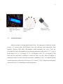
temperature. Figure 1.0 shows the Liquid Crystal Display(LCD) used to display the temperature.
Figure 1.1 shows the thermistor type temperature while figure 1.2 shows the temperature used in
this project that is LM35 temperature sensor.
2
Figure 1.0: LCD
display the temperature
value
1.1
Figure 1.1: Thermistor
type temperature
sensors
Figure 1.2: LM35
Temperature sensor
Problem Statement
Malaysia weather is hot and humid almost all day. The temperature in Malaysia is stable
because it is located within the Equatorial Zone with uniformly high temperatures, high
humidity, relatively light winds, and abundant rainfall throughout the year[1]. From the
encyclopedia of earth, the monthly average maximum temperature ranges from 32- 33° C year in
Kuala Lumpur, 31- 33° C in Penang, 29- 33° C in Kuching, and 30- 32° C in Labuan[1]. This
shows that the temperature in Malaysia is almost the same every day. What will happen to
temperature inside our home when the temperature surrounding is hot? A reasonable thermal
comfort temperature inside a house is between 25.5˚C and 28.5˚C[10]. Temperature inside house
can increase up to 35˚C depending on outside temperature.
3
By using air conditioners or fan, the temperature inside house can be decreases. However,
using air conditioners will consume a lot of electricity especially when it is always turn on.
Using fan continuously will also reduce the fan capabilities over time. The bigger problem is
when the owner is not around but forgot to turn off the cooling systems. This will surely waste
money on electrical bill because the cooling system such as air conditioners and fans is not turn
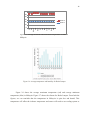
off. Figure 7 shows the result of indoor environmental conditions in modern low-income house
where it shows that the maximum comfort temperature inside house is around 28˚C.
1.2
1.
Objective of Project
To design a user temperature control system that can be controlled remotely by sms
4
2.
To develop a control scheme for sustainable home temperature control
3.
To determine the performance over time and analysis of the home temperature for better
comfort ability inside house
1.3
Scope of Project
This project will be using a house model with two rooms for two fans that functioning as
cooling system for the house. Size of each rooms is about 25cm x 35cm. The temperature sensor
in a ranged of from -55˚C to 150˚C from thermistor type temperature sensor and Integrated
Centigrade Temperature Sensor LM35. This project is specifically for Malaysia weather with
temperature in the range of 20˚C to 40˚C.
1.4
Outline of Thesis
This thesis consist of six chapters. The first chapter deal with the objective and scope of
the project is discussed. Chapter 2 will review on the theory and literature reviews related to this
project. It will discuss on the temperature monitoring system and the temperature control system.
Chapter 3 is about the methodology of the project regarding hardware and software
implimentation. In Chapter 4, the result and discussion will be presented while Chapter 5 is
conclusion and recommendation. The last chapter is Chapter 6 solely about the project
management focusing on the project duration and cost.
5
1.5
Summary of Works
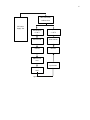
Figure 1.3 shows the overview of SHTC system where it begin with supplying DC
voltage using 12V DC Power Supply to the microcontroller. Temperature sensor will read the
surrounding temperature and display it on LCD. If the temperature is above 26˚C, the red Led
will on and this will aslo activate the fan. Sms alert will be send to the user. If the user reply the
sms sent by the system, the fan will off. If the temperature is below 26˚C, blue Led will light up.
The fan is off and an alert sms will not be sent to the user.
6
Microcontroller
Arduino Uno
DC Power
Supply 12V
Temperature
>= 26˚C
Temperature
<= 26˚C
Red LED ON
Blue LED ON
Fan ON
Fan OFF
SMS send to
user
SMS Receive
by the user
User reply
SMS
Figure 1.3: Overview of SHTC
7
CHAPTER 2
THEORY AND LITERATURE REVIEW
2.0
Introduction
This chapter will discuss about the theory behind Sustainable Home Temperature Control
System and the literature review on this project. The literature review is on previous works that
have been done commercially and academically. Works done are compared to the thesis scope of
work to determine the improvements that has been made in the temperature monitoring system.
2.1
Temperature Monitoring System
Temperature monitoring is a process of reading temperature from time to time[12]. It is
commonly used in many industrial processes and also used for home appliances. The main
function of the temperature monitoring system is only to monitor temperature without doing
anything to adjusting the temperature. It solely purposes is to show the temperature reading to
users. Below are the example of temperature monitoring devices and its specifications.
8
2.1.1 Data Logger Aids Temperature Monitoring
Figure 2.0: Data Logger Aids Temperature Monitoring Device
Figure 2.0 shows the Data Logger Aids Temperature Monitoring Device designed by Lec
Medical Company. It can be used for pharmacies, hospitals, laboratories and clinics. This device
is capable of measuring and storing up to 16,378 temperature readings over a -35˚C to +80˚C
range[2]. The data inside the device can be downloaded by plugging the data logger into a PC’s
USB port. In other words, this device is solely function to record temperature which can
typically allow logging for up to one year and display the recorded temperature into PC. The
device will only display the current temperature on its LCD display and store the previous
reading.
9
2.1.2 Bluetooth Digital Thermometer for Android Devices
Figure 2.1: Bluetooth Digital Thermometer Watch
Figure 2.1 shows the Bluetooth Digital Thermometer Watch where it can monitor body
temperature wirelessly on Android Phone or Tablet via Bluetooth. The upper and lower
temperature can be set the alarms will be triggered to owner’s phone when the temperature is out
of range. The LCD display on the watch will display the current temperature value.
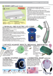
2.1.3 Thermofocus TH1500A3 Non-Contact Clinical Thermometer
Figure 2.2: Thermofocus TH1500A3 Non-Contact
Clinical Thermometer
10
Figure 2.2 shows the Thermofocus Non-Contact Clinical Thermometer where it is the
most modern, advance and safe device to measure body temperature. It is the first non-contact
medical thermometer that enables the temperature of adults and children to be taken without
touching the skin, simply by moving the thermometer close to the forehead at the distance
indicated by the device. It uses infrared technology to instantly read the core body temperature at
the forehead by taking the temperature at the temporal artery[3]. Thermofocus is non-invasive,
totally hygienic, and non-irritating to babies and patients. The thermofocus can also measure the
temperature at the navel or armpit, and can be set to Fahrenheit or Celsius.
2.2
Temperature Control System
Temperature control system is a process where the temperature is being controlled
automatically or manually by the user[7]. Temperature controller is commonly used in industrial
and air conditioning system. Its main function is to control the temperature by adjusting the
heating or cooling element so that the temperature will drop or rise according to user’s
specification. Below are the example of temperature control system devices and its
specifications.
11
2.2.1 Controller for Beer Fermentation and Kegerator
Figure 2.3: Temperature controller device for beer
fermentation and kegerator
Figure 2.3 shows the temperature controller for beer fermentation and kegerator. This
device has one output for cooling control and another for heating control. It can be used for beer
fermentation or convert refrigerator to kegerator. By using both cooling and heating devices, the
refrigerator can be controlled at specific temperature regardless in hot summer or cold winter.
This controller is a plug and play controller. Both the heating and cooling control modes
are simple on/off control, similar to a mechanical thermostat but with much higher precision due
to adjustable hysteresis band, precision sensor and digital read out. Anti-short function is
provided for cooling to protect the compressor from being turned on with high pressure. The
advantage is being much more reliable in moisture environment than thermistor sensor. It can be
12
immersed over extended period of time. It also has a more uniform accuracy over an entire
specified temperature range.
2.2.2 Intelligent Temperature Control Split Air Conditioners
Figure 2.4: Intelligent Temperature Control Split Air
Conditioner
Figure 2.4 shows the Intelligent Temperature Control Split Air Conditioner designed by
Foshan Longrui Electrical Appliances Co. Ltd in China. It is the energy-saving type and super
quite operating with relaxable style like cool breezy. It has wide temperature range from 16˚C to
30˚C. The room’s temperature will be always fixed when used this air conditioners. It will
maintain room temperature by adjusting the cooling or heating element.
2.3
Differences Between Current Devices and This Project
From the above example on temperature monitoring and temperature control system, we
can conclude that the current device is already better but the differences are that the devices still
using a lot of power consumption. The intelligent air conditioner above is a power saving air
13
conditioner because it uses less power consumption than other air conditioners. The air
conditioner is still continuously on unless it is turning off manually. Many devices also have the
communication’s specification that is calling or sms when the temperature is out of range.
However, the function is only to alert user. User cannot do anything from far unless the user is
near the device and turn it on or off. The communication is only for alerting user to let user know
that the temperature is out of range. It is limited only in letting user know.
The SHTC will be design so that these flaws are overcome. SHTC will alert the user via
smartphone’s call or sms and the user can decide whether to reply the call or sms. Users can turn
on/off the cooling system just by using smartphone even when the user is not at home.
2.4
Market Survey
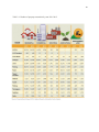
There are many residential in Malaysia and its keep increasing every year. Table 2.1
below shows the number of property transaction in 2011-2012. From the transaction, we know
that the residential is keep increasing every year at least by 300 residential.
14
Table 2.1: Number of property transaction by state 2011-2012
15
60
50
40
30
Series 2
20
Series 1
10
Dec
Nov
Oct
Sept
July
Aug
Jun
May
Apr
March
Jan
Feb
0
Figure 2.5: Average minimum and maximum temperature weather in
Malaysia
Figure 2.6: Average temperature and humidity for Kuala Lumpur
Figure 2.6 shows the average maximum temperature (red) and average minimum
temperature (blue) in Malaysia. Figure 2.7 shows the climate for Kuala Lumpur. From both the
figures, we can conclude that the temperature in Malaysia is quite hot and humid. This
temperature will affect the in-house temperature and owner will need to use cooling system as
16
the weather is hot. The cooling system such as air conditioners will use a lot of power, therefore
the owner need to pay a large amount of money for the usage of air conditioners.
Therefore, the SHTC is design for home appliances for better comfort and to save
electricity consumption. This devices function to turn on/off according to owner’s need or
instructions.
17
CHAPTER 3
METHODOLOGY
3.0
Introduction
This chapter will briefly explain about the flow of the project, the components used, and the
expected outcome.
3.1
Hardware Implementation
3.1.1 DC Motor
The fan used is 12V, 0.3 A. The size of the fan is 8.5cm x 8.5cm. Since the fan uses 12V, 0.3A,
an external power sources to the fan must be applied so that the fan can rotates faster.
18
The microcontroller used does not have enough power or volt to move the fan. Therefore for
each fan, a 9V battery is used.
3.1.2 1602 HD44780 Character LCD Display Module
Liquid Crystal Display with blue backlight. The instruction of each pin is shown in table 3.1
below.
Table 3.1: LCD’s pin instruction
No.
1
2
3
4
5
6
7
8
Symbol
VSS
VDD
VL
RS
R/W
E
D0
D1
Pin instruction
GND
Positive
LCD Bias voltage
Data/Command choice
Read/Write choice
Enable signal
Data
Data
No.
9
10
11
12
13
14
15
16
Symbol
D2
D3
D4
D5
D6
D7
BLA
BLK
Pin instruction
Data
Data
Data
Data
Data
Data
Back light anode
Back light cathode
The first pin: VSS means GND
The second pin: VDD connect +5v
The third pin: VL is the terminal of LCD for adjusting the contrast. Connecting anode, the
contrast is weak; connecting GND, contrast is high. Contrast is too high which will result in
‘ghost’.10k potentiometer can be used to adjust the contrast in operation’.
The fourth pin: It is register choice. High level, choose data register, Low level, choose
instruction register.
19
The fifth pin: R/W is signal wire of ‘read’ and ‘write’. High level, execute ‘read’, Low level,
execute ‘write’. When RS and R/W are at low level simultaneously, you can write command or
show address. When RS&R/W are at high level simultaneously, you can read the busy signal;
When RS is at high level and R/W is at low level, you can write data.
The sixth pin; E terminal is enable terminal. When E terminal becomes from high level to low
level, LCD module executes command.
The seventh pin: D0 to D7 is 8 pin bi-directional data cable
The fifteenth pin: Black light anode
The sixteenth pin: Black light cathode
3.1.3 Temperature Sensor
There are two temperature sensors used in this project that is SN-TEMP-MOD shown in
Figur 3.1 and LM35 shown in figure 3.2. SN-TEMP-MOD comes with two outputs, analog and
digital. This temperature module uses NTC Thermistor to detect temperature changes with
onboard components providing power of 3.3V to 5V DC. Negative Temperature Coefficient
(NTC) thermistor will change the effective resistance over temperature, utilizing this behavior.
13
Room/environment temperature may be detected by measuring the voltage from a resistor
network, like a voltage divider. However, this module is not suitable to measure absolute
temperature and is suitable for relative temperature measurement. Below is the front view of SNTEMP-MOD temperature sensor.
Figure 3.1: Temperature sensor module board layout
20
This temperature sensor is sensitive to environment temperature and the sensitivity can be
adjusted for digital output with on board potentiometer, clockwise will set the threshold at low,
and counter clockwise will set the threshold at temperature high for trigger. When the actual
temperature is higher than threshold, D0 will be LOW and wise versa. A0 is around 1.45V at
27˚C and the higher the temperature, the lower the voltage at A0.
LM35 are precision centigrade temperature sensor whose output is linearly proportional
to the Celsius (Centigrade) temperature. It does not require any external calibration or trimming
like SN-TEMP-MOD to provide typical accuracies of ±1/4˚C at room temperature over a full 55˚C to 150˚C temperature range. Figure 3.3 shows the upper view of LM35 where it has three
pins which is Vs pin for voltage to the LM35, Vout for voltage to the microcontroller, and GND
for ground.
Figure 3.2: LM35 Schematic diagram
Figure 3.3: LM35 Upper view
21
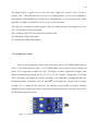
3.1.4 SIM900 GSM Shield
GSM is known as Global System of Mobile Communication. It is being used as standard
for nowadays in our cell phone. Over 200 countries and 2 billion people are using it as a phone
today. GSM would work any place as long as the signal/network is available. SIM900 can be
used in a wide range of application. For this project, SIM900 is used for sending and receive
SMS only. Table 3.2 below shows the features of SIM900.
Table 3.2: SIM900 GSM Shield Features
Feature
Power Supply
Power Saving
Frequency Bands
Temperature Range
-
Data GPRS
SMS
-
Real Time Clock
Explaination
3.2V ~ 4.8V
Typical power consumption in sleep mode is 1.0mA
SIM900 Quad-band: can search the 4 frequency bands automatically
Compliant to GSM Phase 2/2+
Normal operation: -30˚C ~ +80˚C
Restricted operation: -40˚C ~ -30˚C and +80˚C ~ +85˚C
Storage temperature: -45˚C ~ +90˚C
GPRS data downlink transfer max 85.6kbps
GPRS data uplink transfer max 42.8 kbps
MT, MO, CB, Text and PDU mode
SMS Storage: Sim Card
Support RTC
The following figure shows a functional diagram of SIM900 and overview of SIM900
GSM/GPRS Shield.
22
Figure 3.4: Functional block diagram of
Sim900 GSM Shield
Figure 3.5: Sim900 GSM Shield
Figure 3.6: Sim900 GSM Shield Schematic
23
Figure 3.6 shows the schematic of Sim900 GSM Shield where it already has its own
microcontroller pins to be attached to Arduino Uno.
3.1.5 Light Emitting Diodes (LEDs)
Two blue leds and red leds will be used. The leds used is 5mm led. The blue LEDs will indicate
that the temperature is below 26˚C while the red LEDs will indicate that the temperature is above
26˚C.
3.1.6 Microcontroller Arduino Uno
Arduino is an open-source electronics prototyping platform based on flexible, easy-to-use
hardware and software. Arduino can sense the environment by receiving input from a variety of
sensors and can affect its surroundings by controlling lights, motors, and other actuators. The
microcontroller on the board is programmed using the Arduino programming language(based
on Wiring) and the Arduino development environment (based on Processing). Arduino projects
can be stand-alone or they can communicate with software running on a computer.
24
3.2
Software Implementation
In this project, one main software is used that is Arduino IDE for programming the
microcontroller. Arduino IDE using Atmega328 programming such as assembly and high level
language. The Arduino programming language is an implementation of Wiring, a similar
computing platform, which is based on the processing multimedia programming environment.
The Arduino software is published as open source tools, available for extension by experienced
programmers. The language can be expanded through C++ libraries, and people wanting to
understand the technical details can make the leap from Arduino to the AVR C programming
language on which it’s based.
Figure 3.7: Arduino IDE open-source software overview
Figure 3.7 shows the overview of Arduino IDE open-source software used to programm
the Arduino Uno. Assembly language and high level language can be used for coding or
programming.
25
CHAPTER 4
RESULT AND DISCUSSION
4.0
Introduction
This chapter will show the result of project research and discuss several experiments or
testing that has been made for better understanding of the project research.
4.1
Flowchart
From the flowchart as shown in figure 4.1, the process begins with reading value from
temperature sensors and displays the reading on Liquid Crystal Display (LCD) 16x02cm. The
decision will be taken when the temperature is out of range. The range for in-house starting hot
temperature is 26˚C. When the temperature is below 26˚C, the blue Led will turn on while the
cooling system will not turn on but when the temperature is above 26˚C, the red Led will turn on
and the cooling system will also turn on. When the temperature goes above 26˚C, the GSM will
send SMS. Its is up to the user whether tp reply it or not. When the user reply the SMS or
26
sending the SMS to the system, the fan will automatically of regardless of the temperature value.
The process in the flowchart is a basic idea for automatic temperature control.
Figure 4.1: Flowchart diagram of the whole
process of SHTC
27
4.2
Main Component With GSM Module
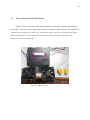
Figure 4.2 below shows the main components that are already available and attached to
one another. Two fans and two temperature sensors is attached to the main body. The GSM Shield
is attached to the Arduino Uno. LEDs, LCD, Temperature sensors, and fans are connected to the GSM
Shield using Arduino Uno pins. Figure 4.3 shows the connection of LCD,Leds, DC Motor, and
temperature sensors to Arduino Uno.
Figure 4.2: SHTC Devices
28
Figure 4.3: shows the connection of Arduino Uno, LCD, LEDs, DC Motors, and temperature sensors.
4.3 Block Diagram
Figure 4.4 below shows the block diagram of Sustainable Home Temperature Control
Device where it begins with the temperature sensors that will send feedback to the
microcontroller Arduino Uno. The Leds and fans will activated based on the temperature value
whether it is hot or cold. LCD will display the temperature value and an alarm will triggered if
the temperature is above 26˚C. This will cause the system to alert the user by sending sms and
the user can choose whether to deeactivate the fans or not by replying sms if the user want to
deactivate it.
29
LEDs
Temperature
Sensors
Trigger
alarm when
out of range
Microcontroller
Arduino Uno
Send
sms
Fan
on/off
LCD Display
Figure 4.4: Block diagram of Sustainable Temperature Control
System
4.4 Result
4.4.1 Preliminary Result
The preliminary result is result obtain from the first semester of Final Year Project.
During the first semester, the result is more on the learning on how to program and assemble the
component used.In appendix A1 show the coding for the LM35 temperature sensor and display
it on the LCD and computer monitor.
In Appendix A2 shows the coding for the Red and Blue Led to light up. Blue Led is light
up first, then the red Led will light up. After one second, the blue and the red Led will light up
then both will turn off.
30
In the first semester, the fans and the GSM SIM900 is still not bought because of money
problem. Therefore the LCD, and the Leds is test out first. However, a fan from the laptop
cooling pad is used first to test out the LM35 sensor. Below is the overview of the first prototype
without the GSM module.
Figure 4.5: Preliminary devices connection
From the figure 4.5, The LM35 is connected to anaog pin(A0) of arduino, the blue Led to
digital pin 8 of arduino, red Led to digital pin 12, and the fan is connected to digital pin 3 of
arduino. The fan using the power from the battery so that the fan can rotates faster. Transistor
NPN is used to supply the power from 9V battery to the fan. The coding for the fisrt protoype
without the GSM module is appendix A3.
31
4.4.2 Final Result
The final result will include two LM35 temperature sensor, two fans(DC Motor), LCD
display, two red Leds, two blue Leds, and SIM900 GSM Shield. The LM35 temperature sensor
will measure the temperature inside two mini rooms. The temperature will be display on the
LCD. If the temperature goes beyond 26˚C, the red Led will light on and the SMS from the
system will be sent to the user. The user will receive the alert SMS indicating that whether mini
room 1 or mini room 2 is hot. User can choose whether to reply the SMS or not. If the SMS is
replied, the cooling system will be turn off. If the SMS is not replied, the cooling system will be
turn On. User will receive SMS from the system in another six hours after the system receive a
replied SMS from the user if the temperature is still beyond 26˚C in those six hour.
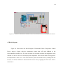
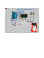
Figure4.6 shows and overview and the schematic of the main system without GSM
connection.
32
Figure 4.6: overview of SHTC’s connection
33
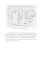
Figure 4.7: overview of SHTC’s schematic diagram.
The schematic in figure 4.7 shows the connection of the system without the GSM
SIM900 since the SIM900 does not have fritzing file. The GSM Shield SIM900 will be using the
TX and RX pin of arduino that is digital pin 0 and digital pin 1. TX pin is for transmit signal
from the GSM Shield and the RX pin is for receive signal to the GSM Shield. GSM Shield
SIM900 pin’s for arduino is pin 2 of TX and pin 3 of RX. Figure 4.8 below shows the pin of
GSM Shield to be used for arduino uno.
34
Pin 3 TX
of GSM
Pin 2 RX
of GSM
Figure 4.8: TX and RX pin of Sim900 GSM Shield
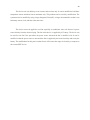
Figure 4.9 show the final product of the project where it consist of 4 port, two port for
temperature sensors and two port for fans.
Antenna of GSM Shield
Adjusting contrast of
LCD
LCD Display
Leds for mini
room 1
Leds for mini
room 2
Fans
Temperature
sensors
Figure 4.9: SHTC main components
35
The temperature sensor is tested by taking the temperature readings from mini room 1
and mini room 2. Table 4.2 below show the reading taken before the fans is attached.
Table 4.2: Mini room’s normal temperature reading
Time (s)
0
10
20
30
40
50
60
70
80
90
100
110
120
130
Temp1(˚C)
0
29.1
29.1
29.6
29.6
30
30
30
29.7
29.7
30.1
30.1
30.1
30.5
Temp 2 (˚C)
0
29.1
29.1
29.1
29.6
29.6
29.6
30
30
29.7
30.1
30.1
30.1
31.1
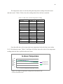
From the table above, the average mini room temperature before the fans is on is about
29.8˚C for both mini rooms. Table 4.3 and Figure 410 below shows the value of the temperature
readings when the fans is apllied to the mini rooms.
In-House Temperature
Temperature ˚C
40
30
20
Temperature 1
10
Temperature 2
0
2 4 6 8 10 12 14 16 18 20 22 24 26 28 30 32 34 36
Figure 4.10: Graph of temperature reading before and after the fans
is on for both mini rooms
36
Table 4.3: Temperature reading before and after the fans is on for
both mini rooms
Time(Minutes) Temperature 1
Temperature 2
29.1
29.1
2
29.1
29.1
29.6
29.1
4
29.6
29.8
30
29.8
6
30
30.3
29.7
30.3
8
29.6
30.9
29.7
30.9
10
30
30.3
30.1
29.8
12
30.5
29.8
31.1
29.1
14
31.4
28.7
31.1
28.7
16
31.1
28
30.1
28.3
18
30
27.9
30
27.6
20
30
27.5
29.1
27.1
22
28.7
27.1
28.4
26.5
24
28
26.5
28
26
26
27.4
26
27
25.4
28
26.6
25.4
26.2
24.9
30
25.7
24.9
25.5
24.4
32
25.7
24.2
25.5
24.2
34
24.9
24.4
24.4
24.4
36
24.4
24.2
37
From the graph shown above, the time taken for the mini room to cool down below 26˚C
when the fans is on is around 20 minutes for room size 25cm x 35cm. However, this is only true
for the normal average room temperature around 29.8˚C. The graph show the decreasing
temperature after both of the fans is on aroun minutes 15.
When the temperature is above 26˚C, the red Led will turn on and the sms will be sent to
the user. User can reply the sms to turn off the fans. Figures below shows the process of the
system.
Figure 4.11: Mini room model consist of two rooms
The house model for the system consist of one fan and one temperature sensor for each
room as shown in Figure 4.11. There is two rooms in this house model. The main body is
attached outside the house model while the sensors and the fans is inside the mini rooms. A glass
wall is used as the front wall and the roof so that the fans can be observe clearly whether it is on
or not.
38
Figure 4.12: The red Led for both mini rooms is light up
Temperature exceed 26˚C will light up the red leds. From the figure 4.12, both the leds is
on because both of mini room’s temperature is above 26˚C. Both of the fans will automatically
on when the temeprature exceed 26˚C.
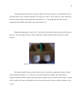
Figure 4.13: SMS received by the user sent from the system
The high temperature will result in the system sending sms to the user to alert the user
about the rising temperature value whether in mini room 1 or mini room 2 as shown in Figure
4.13. The sms will state whether mini room 1 or mini room 2 or both rooms is hot.
39
Figure 4.14: User reply the received SMS.
User can decide whether to reply sms or not. By replying the sms as shown in Figure
4.14, user can turn off the fans even if the room is hot. Even without notification about the
exceeding temperature, user can still send sms to the system to turn off the fans. Any text or
words can be used to send to the system. The system will send sms again after six hour after
receiving the sms from the user if the temperature maintain above 26˚C during those six hour.
Below shows the details about how the sms is send and receive by the user.
(a)
(b)
40
(c)
(d)
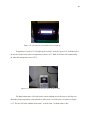
Figure 4.15: Serial print from the computer shows the GSM process (a) for the
temperature reading, (b) GSM Testing, (c) Indicate that GSM is Ready, (d) SMS is
sent
Figure 4.15e: Serial print from the computer shows the GSM process
for the SMS Reply
Figure 4.15a show the temperature reading from the surrounding. When the temperature
exceed 26˚C, the GSM Shield SIM900 will be tested first as shown in figure 4.15b. Figure 4.15c
show the GSM is ready whether to send or receive sms while Figure 4.15d show the sms is sent
41
by the Sim900 GSM Module. Figure 4.14e show sms is replied by the user. The coding for
overall process is shown in appendix A4..
42
CHAPTER 5
CONCLUSION AND RECOMMENDATION
5.1
Conclusion
The SHTC will be a better solution to users who have problems especially when forgotting to turn
off the cooling system. The user can turn off the cooling system without having to go back to their home.
However, since the device only uses a mere 12V DC power supply and operates at 5V power, it is not
suitable to be used using a real fan especially an air conditioner. This project shows how the user can
automatically control the cooling system by an automated sytem and simply using sms.
5.2
Recommendation
The SHTC will be using a prepaid sim card. Therefore it will cost more in term of communication
cost. Each sms is charge one cent depending on the prepaid sim card type. There are a lot of prepaid plan
so that user can choose which plan to use for the system to minimize the sms cost. This problem cannot
be solved by removing the sim card. However, the sms cost can be minimise using a chaper plan for
prepaid sim card. User need to cleverly choose which prepaid plan is the cheapest and the top up renew is
longest.
43
This device can only hold up to two sensors and two fans only. It can be modified to hold three
temperature sensors and three fans at maximum only. This problem can be solved by modification. The
system need to be modified by using a larger Integrated Circuit(IC) or larger microcontroller so that it can
hold many sensors, leds, and fans at the same time.
The device can not be applied to real fan especially air conditioner since real fan need a power
source directly from the electrical plug. The fan in this device is supplied by 9V battery. The device can
be used for real fan if the part where the power source activated the fan is modified a bit. It can be
modified so that the power source to activated the fans is supplied by the home electricity and not by the
battery. The modification for this part is not hard but it will increase the usage of electricity as compare to
the current SHTC device.
44
CHAPTER 6
PROJECT MANAGEMENT
6.0
Introduction
This chapter will explain details about the project schedule and the cost of the project.
Gantt chart is used to shows the shcedule based on each stage of study. There will be two gantt
chart for two semester during this one year project.
The cost estimation will shows the overall cost for this project.
6.1
Project Schedule
Table below shows the gantt chart. Since the final year project consist of two part or two
semester, the gantt chart also divided into semester. Table 6.1 show the gantt chart for semester
one while table 6.2 show the gantt chart of semester two, the continuation of semester one’s gantt
chart.
45
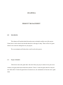
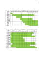
Table 6.1: Gantt chart for semester one
Table 6.2 : Gantt chart for semester two(continuation of semester one)
46
For the first semester, the final year project begins with project briefing and literature
review. We need to find our own title and suggest it to project supervisor that has been assigned
to each student. The literature review will be continuously search for better understanding on the
project. After the project has been chosen and verified by supervisor, a Gantt chart is prepared so
that it will keep the project in motion. The components are prepared. For the first semester, only
the main component is prepared because of lack of budget.
6.2
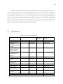
Cost Estimation
Table 6.3: Cost for main components
Component Name
Arduino Uno R3
iComsat
GSM/GPRS Shield
Module
1602 HD44780
Character LCD
Display Module
Male to male
breadborad wire
jumper
Mini jumper
Female to female
jumper
DC 12V 0.3A
Cooling fan
Project Board
Solder Lead
Temperature
Sensor LM35
Transistor NPN
2N3904
Hot glue
Cost
For 1
module
Subtotal(For 1
Unit)
Unit Range
1
1
Price
RM 58.00
RM 240.00
1
1
RM 58.00
RM 240.00
1
RM 12.00
1
RM 12.00
10 - 20
RM 1.10
10
RM 11.00
10 - 20
1
RM 0.20
RM 4.50
5
1
RM 1.00
RM 4.50
1-4
RM 6.00
2
RM 12.00
1
1
1-5
RM 17.00
RM 32.00
RM 8.00
1
1
2
RM 17.00
RM 32.00
RM 16.00
1–5
RM 0.20
2
RM 0.40
1–2
RM 1.90
1
RM 1.90
Subtotal RM 405.80
47
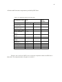
All other small electronics component is provided by FKE Store.
Table 6.4: Components obtain from FKE Store
Component Name
Straight Pin
Header(Male)
Straight Pin
Header(Femlae)
Donat/Matric board
PCB Connector 2
ways
PCB Connector 4
wyas
PCB Stand
Potentiometer
50kΩ
Battery9V
Battery holder
Leds
Crown Pin
Resistor 330Ω
Cost
For 1
module
Unit Range
1 - 20
Price
-
10
1 - 20
-
20
1–3
1 – 10
-
1
4
1 – 10
-
4
1 – 12
1–2
-
4
1
1–6
1–6
1 – 15
10 – 30
1 – 10
-
2
2
4
12
4
Therefore, the overall cost of SHTC device exclude the components obtain from FKE Store is
RM 405.80. The components that are bought is as in table 6.3.
48
REFERENCES
[1]. Mark McGinley,”Climate of Malaysia”, Weather & Climate Meteorology Geography, The
Encyclopedia OF EARTH, June 2011.
[2]. Julia A. Garrido,”New Data Logger Aids Temperature Monitoring and Calibration”, Lec Medical,
Wentworth Communications Ltd, Oct 2012
[3]. Goldwei user manual,” Thermofocus TH1500A3 Non-Contact Clinical Thermometer Against H1N1
Flu”, Goldwei Corp, 2013, http://www.goldwei.com/products/item.asp?itemid=2
[4]. Tellurex,”An Introduction to Temperature Control of Thermoelectric System”, A Guide to
Temperature Control of Thermoelectric System, Tellurex Corp, Transverse City, 2010
[5]. Betreuer, Bassem Ben Yahia,” Temperature Control of a Continuos Water Heater”, Praktikum
Bioverfahrenstechnik, 2013
[6.] Auber Instrument,”TD100 Temperature Controller Instruction Manual”, Auber Instrument Inc, May
2013
[7]. Zhixue Dong, Yila Su, Xiangyong Yan,” Temperature Control System of the Thermal Analyzer
Based on Fuzzy PID Controller”, Ninth International Conference on Hybrid Intelligent System, Inner
Mongolia University of Technology, 2009
[8]. Huang Wen-tian, Li Jin-Ping,” Research and Design of Intelligent Temperature Control System”,
College of Information Beijing Union University, Beijing. 2010
[9]. Aurel-Cornel Stanca, Venetia Sandu, Remus Vaduva, Oszkar Neneth,”Distributed System for Indoor
Temperature Control”, Transilvania University of Brasov.2012
[10]. Joo Tick Lim, Azizan Abu Samah,”Weather and Climate of Malaysia”,University of Malaya Press,
2004. Pg 5,53,159-170
[11]. Aminatuzuhariah Megat Abdullah,” Introduction to Environmental Management System”, UTM
Press, First Ed, 2007. Pg 20-30
[12]. Dogan Ibrahim,”Microcontroller-Based Temperature Monitoring and Control”, Newnes Publication,
Wilwood Avenue, 2002 First Edition. Pg 55-61
49
APPENDICES
A1. Programming code to display temperature value to LCD
#include<LiquidCrystal.h>
LiquidCrystal lcd(6,7,8,9,10,11);
float temp1;
int temp1Pin = 0;
void setup()
{
Serial.begin(9600);
Lcd.begin(16,2);
Serial println(“Temperature Sensor Value”);
}
void loop()
{
temp1 = analogRead(temp1Pin);
temp1 = temp1 * 0.48828125;
delay(1000);
temp1 = temp1 * 0.48828125;
delay(1000);
Serial.println(temp1);
lcd.clear();
lcd.setCursor(1,0);
lcd.print(“temp1 = “);
lcd.print(temp1);
delay(100);
}
50
A2. Programming code for Leds
int BlueLed = A5;
int RedLed = A4;
void setup()
{
pinMode (BlueLed, OUTPUT);
pinMode (RedLed, OUTPUT);
}
void loop()
{
analogWrite (BlueLed, HIGH);
analogWrite (RedLed,LOW);
delay(1000);
analogWrite (BlueLed,LOW);
analogWrite (RedLed,HIGH);
delay(1000);
analogWrite (BlueLed,HIGH);
analogWrite (RedLed,HIGH);
delay(1000);
analogWrite (BlueLed,LOW);
analogWrite (RedLed,LOW);
delay(1000);
}
51
A3. Programming code for device without GSM
#include<Servo.h>
Servo servol;
float temp;
int tempPin = 0;
int fan1 = 2;
int led1 = 12; int led2 = 8;
int pos = 0;
void setup()
{ Serial.begin(9600);
pinMode (fan1,OUTPUT);
pinMode (led1,OUTPUT);
pinMode (led2,OUTPUT);
servol.attach(9); }
void loop()
{
temp = analogRead(tempPin);
temp = temp * 0.48828125;
delay(1000);
Serial.println(temp);
if (temp > 33)
{
pos = 180;
digitalWrite (fan1,HIGH);
digitalWrite (led1,HIGH);
digitalWrite (led2,LOW);
servol.write(pos);
}
else
{
pos = 90;
digitalWrite (fan1, LOW);
digitalWrite (led1, LOW);
digitalWrite (led2,HIGH);
servol.write(pos);
}
delay(3000);
}
52
A4: SHTC’s programming
/*
Temperature Control System using 2 temperature sensors,
2 fans, lcd, and 4 leds.
led1 to pin A5
led2 to pin A4
led3 to pin A3
led4 to pin A2
temp1 to pin A1
temp2 to pin A2
fan1 to pin 4
fan2 to pin 5
LCD(vss,vdd,v0,rs,rw,e,d0,d1,d2,d3,d4,d5,d6,d7,a,k)
LCD(GND,+5v,middle pin of contrast,pin 5,GND, pin 6,_,_,_,pin 8,pin9, pin 10, pin 11,
+5v,GND)
Contrast(1st pin GND, middle pin to LCD, 3rd pin to +5v)
When temperature >=26 degree C
-fan ON
-SMS from GSM
When temperature <=26 degree C
-fan OFF
if the user reply SMS, the fan will OFF
Created 10 May 2014
by Azeo Hafizie / UTM FYP
[email protected]
*/
#include<LiquidCrystal.h>
#include "SIM900.h"
#include <SoftwareSerial.h>
#include "sms.h"
SMSGSM sms;
LiquidCrystal lcd(6,7,8,9,10,11);
float temp1;
float temp2;
int temp1Pin = 0;
int temp2Pin = 1;
int fan1 = 4;
53
#include "SIM900.h"
#include <SoftwareSerial.h>
#include "sms.h"
SMSGSM sms;
LiquidCrystal lcd(6,7,8,9,10,11);
float temp1;
float temp2;
int temp1Pin = 0;
int temp2Pin = 1;
int fan1 = 4;
int fan2 = 5;
int pos = 0;
int led1 = A5;
int led2 = A4;
int led3 = A3;
int led4 = A2;
int numdata;
boolean started=false;
char smsbuffer[160];
char n[20];
void setup()
{
Serial.begin(9600);
lcd.begin(16,2);
pinMode (fan1,OUTPUT);
pinMode (fan2,OUTPUT);
pinMode (led1, OUTPUT);
pinMode (led2, OUTPUT);
pinMode (led3, OUTPUT);
pinMode (led4, OUTPUT);
Serial.println("SMS Messages Sender");
boolean notConnected = true;
Serial.println("GSM Shield testing.");
//if (gsm.begin(2400))
//{
// Serial.println("\nstatus=READY");
// started=true;
// }
// else Serial.println("\nstatus=IDLE");
54
//if (gsm.begin(2400))
//{
// Serial.println("\nstatus=READY");
// started=true;
// }
// else Serial.println("\nstatus=IDLE");
}
void loop()
{
temp1 = analogRead(temp1Pin);
temp2 = analogRead(temp2Pin);
temp1 = temp1 * 0.48828125;
temp2 = temp2 * 0.48828125;
delay(1000);
Serial.println(temp1);
Serial.println(temp2);
delay(100);
lcd.clear();
lcd.setCursor(1,0);
lcd.print("temp1 = ");
lcd.print(temp1);
delay(100);
lcd.setCursor(0,7);
lcd.print("temp2 = ");
lcd.print(temp2);
delay(1000);
if (temp1 && temp2 > 26)
{
pos = 180;
digitalWrite (fan1,HIGH);
digitalWrite (fan2,HIGH);
digitalWrite (led1, LOW);
digitalWrite (led2, HIGH);
digitalWrite (led3, LOW);
digitalWrite (led4, HIGH);
if (gsm.begin(2400))
{
Serial.println("\nstatus=READY");
started=true;
}
55
digitalWrite (led2, HIGH);
digitalWrite (led3, LOW);
digitalWrite (led4, HIGH);
if (gsm.begin(2400))
{
Serial.println("\nstatus=READY");
started=true;
}
else Serial.println("\nstatus=IDLE");
if(started)
{
if (sms.SendSMS("+601136559465", "Both Temp Exceed 26"))
Serial.println("\nSMS sent OK");
delay(30000);
}
if(started)
{
if(gsm.readSMS(smsbuffer, 160, n, 20))
{Serial.println(n);
Serial.println(smsbuffer);
digitalWrite (fan1,LOW);
digitalWrite (fan2,LOW);
delay(10000);
}
}
delay(60000);
}
else if (temp1 && temp2 < 26)
{
pos = 90;
digitalWrite (fan1, LOW);
digitalWrite (fan2, LOW);
digitalWrite (led1, HIGH);
digitalWrite (led2, LOW);
digitalWrite (led3, HIGH);
digitalWrite (led4, LOW);
}
else if (temp1 > 26 && temp2 < 26)
{
pos = 180;
digitalWrite (fan1,HIGH);
digitalWrite (fan2,LOW);
56
digitalWrite (led3, HIGH);
digitalWrite (led4, LOW);
}
else if (temp1 > 26 && temp2 < 26)
{
pos = 180;
digitalWrite (fan1,HIGH);
digitalWrite (fan2,LOW);
digitalWrite (led1, LOW);
digitalWrite (led2, HIGH);
digitalWrite (led3, HIGH);
digitalWrite (led4, LOW);
if (gsm.begin(2400))
{
Serial.println("\nstatus=READY");
started=true;
}
else Serial.println("\nstatus=IDLE");
if(started)
{
if (sms.SendSMS("+601136559465", "Temp1 Exceed 26"))
Serial.println("\nSMS sent OK");
delay(60000);
}
if(started)
{
if(gsm.readSMS(smsbuffer, 160, n, 20))
{
Serial.println(n);
Serial.println(smsbuffer);
digitalWrite (fan1,LOW);
digitalWrite (fan2,LOW);
delay(10000);
}
}
}
else if (temp1 < 26 && temp2 > 26)
{
pos = 180;
digitalWrite (fan1,LOW);
digitalWrite (fan2,HIGH);
57
}
}
else if (temp1 < 26 && temp2 > 26)
{
pos = 180;
digitalWrite (fan1,LOW);
digitalWrite (fan2,HIGH);
digitalWrite (led1, HIGH);
digitalWrite (led2, LOW);
digitalWrite (led3, LOW);
digitalWrite (led4, HIGH);
if (gsm.begin(2400))
{
Serial.println("\nstatus=READY");
started=true;
}
else Serial.println("\nstatus=IDLE");
if(started)
{
if (sms.SendSMS("+601136559465", "Temp2 Exceed 26"))
Serial.println("\nSMS sent OK");
delay(60000);
}
if(started)
{
if(gsm.readSMS(smsbuffer, 160, n, 20))
{
Serial.println(n);
Serial.println(smsbuffer);
digitalWrite (fan1,LOW);
digitalWrite (fan2,LOW);
delay(10000);
}
}
delay(3000);
}}