1
PSZ 19:16 (Pind. 1/07)
UNIVERSITI TEKNOLOGI MALAYSIA
DECLARATION OF THESIS / UNDERGRADUATE PROJECT PAPER AND COPYRIGHT
Author’s full name
Date of birth
Title
:
MUHAMMAD IZUAN BIN ABDULLAH
:
27 MARCH 1988
:
INDUSTRIAL ILLEGAL TOXIC WASTE DISPOSAL VIA SMART DETECTION
SYSTEM
Academic Session :
2011/2012
I declare that this thesis is classified as :
CONFIDENTIAL
(Contains confidential information under the Official
Secret Act 1972)*
RESTRICTED
(Contains restricted information as specified by the
organisation where research was done)*
OPEN ACCESS
I agree that my thesis to be published as online open
access (full text)
I acknowledged that Universiti Teknologi Malaysia reserves the right as follows:
1. The thesis is the property of Universiti Teknologi Malaysia.
2. The Library of Universiti Teknologi Malaysia has the right to make copies for the
purpose of research only.
3. The Library has the right to make copies of the thesis for academic exchange.
Certified by :
SIGNATURE
880327-05-5117
(NEW IC NO./PASSPORT NO.)
Date :4th JULY 2012
NOTES :
*
SIGNATURE OF SUPERVISOR
DR. SOPHAN WAHYUDI BIN NAWAWI
NAME OF SUPERVISOR
Date :4th JULY 2012
If the thesis is CONFIDENTIAL or RESTRICTED, please attach with the letter from
the organization with period and reasons for confidentiality or restriction.
“I hereby declare that I have read this report and in my option this report is sufficient
in term of scope and quality for the award of Bachelor’s Degree of Electrical
Engineering (Control & Instrumentation)”
Signature
:
……………………………
Name of Supervisor
:
DR. SOPHAN WAHYUDI BIN NAWAWI
Date
:
4 th JULY 2012
i
INDUSTRIAL ILLEGAL TOXIC WASTE DISPOSAL VIA SMART
DETECTION SYSTEM
MUHAMMAD IZUAN BIN ABDULLAH
A thesis submitted in fulfilment of the
requirements for the award of the degree
of Bachelor in Electrical Engineering
(Control & Instrumentation)
Faculty of Electrical Engineering
Universiti Teknologi Malaysia
JULY 2012
ii
“I declare that this report entitled “Industrial Illegal Toxic Waste Disposal via
Smart Detection System” is the results of my own effort with the exception of
excerpts cited in the references. This thesis has not been accepted for any degree
and is not currently submitted in candidature of any other degree.”
Signature
:
…………………………………….
Name
:
MUHAMMAD IZUAN BIN ABDULLAH
Date
:
4th JULY 2012
iii
Dedicated to my beloved mom and dad,
Basariah binti Abdullah Sani and Abdullah bin Mohd Shahrani,
and both my sisters.
A special thanks for all your support, encouragement and understandings.
Thank you for everything
iv
ACKNOWLEDGEMENT
‘In The Name of ALLAH, The Most Gracious and The Most Merciful’
Alhamdulillah for the health, patience and endless courage that has been
given to me from The Most Gracious that finally I successfully finished my final
year project. First and foremost, I would like to convey my sincere gratitude to the
people that has been supporting me all this while from the start to finish, overcoming
every various moment, good or bad over the past two semesters.
Much thanks to my supervisor, Dr Sophan Wahyudi bin Nawawi for his
invaluable guidance and suggestion throughout the process of completing this
project. The calmness and faith of him to me has given me the strength and believe
that completing this project was never impossible.
My appreciation also goes to my family especially my parents who has been
so tolerant and supports me all these years. Thank for their encouragement, love and
emotional supports that they had given to me.
Lastly, I would also like to extend my sincere appreciation to my fellow
friends those whom involve directly or indirectly with this project who always
willingly to give their time and effort when I need most. There is no much
meaningful word that may repay their supportive and creative idea for this project.
v
ABSTRACT
In pursuing the goal of becoming a fully developed nation by the year
2020, pollution are among the main problems that still haunt the country. Water
pollution in particular has occurred mainly due to the irresponsibility action of the
industries that dispose the toxic and hazardous waste into the river. To prevent this
action from happening, this project was created to detect any attempt from the
industries to dispose their generated toxic or hazardous waste from the septic tank to
the river. Built using an electrochemical gas sensor to detect the toxic being dispose,
it will sense the toxic gas and send the address location of the industry who commit
the offense to the authorities for further action. The system used GSM technology
that integrated with a microcontroller to send and receive data wirelessly. A GSM
Modem is used to send the address location of the industry via Short Messaging
Service (SMS) whenever a toxic waste disposal is detected while a GSM phone is
used to receive the SMS. Visual Basic programming is used to develop the GUI for
the system in purpose to display the data received at the monitoring location.
Through this project, a reliable and effective system is achieved to prevent the illegal
toxic waste disposal by the industries.
vi
ABSTRAK
Dalam usaha untuk mencapai matlamat menjadi sebuah negara maju
sepenuhnya menjelang tahun 2020, pencemaran adalah antara masalah utama yang
masih menghantui negara. Pencemaran air khususnya telah berlaku disebabkan oleh
tindakan tidak bertanggungjawab industri yang melupuskan sisa toksik dan
berbahaya ke dalam sungai. Bagi menghalang tindakan ini daripada berlaku, projek
ini telah diwujudkan untuk mengesan mana-mana percubaan dari industri untuk
melupuskan sisa toksik atau berbahaya yang dihasilkan dari tangki septik ke sungai.
Dibina dengan menggunakan sensor gas elektrokimia untuk mengesan sisa toksik
yang dilupuskan, ia akan mengesan gas toksik dan menghantar alamat lokasi industri
yang melakukan kesalahan itu kepada pihak berkuasa untuk tindakan selanjutnya.
Sistem ini menggunakan teknologi GSM yang disepadukan dengan mikropengawal
untuk menghantar dan menerima data tanpa wayar. Modem GSM digunakan untuk
menghantar lokasi alamat industri melalui Khidmat Pesanan Ringkas (SMS) apabila
pembuangan sisa toksik dikesan manakala telefon GSM digunakan untuk menerima
SMS. Pengaturcaraan Visual Basic digunakan untuk membangunkan GUI bagi
sistem bertujuan untuk memaparkan data yang diterima di lokasi pemantauan.
Melalui projek ini, satu sistem yang boleh dipercayai dan berkesan dapat dicapai bagi
mencegah pembuangan sisa toksik haram oleh industri.
vii
TABLE OF CONTENTS
CHAPTER
TITLE
PAGE
DECLARATION
ii
DEDICATION
iii
ACKNOWLEDGEMENTS
iv
ABSTRACT
v
ABSTRAK
vi
TABLE OF CONTENTS
vii
LIST OF TABLES
LIST OF FIGURES
1
2
x
xi
LIST OF SYMBOLS AND ABBREVIATIONS
xiii
LIST OF APPENDICES
xv
INTRODUCTION
1
1.1
Background
1
1.2
Problem Statement
2
1.3
Objectives
3
1.4
Scope of Project
3
1.5
Project Planning
4
1.6
Methodology
6
1.7
Thesis Outline
8
LITERATURE REVIEW
9
2.1
Literature Background
9
2.2
Toxic Waste
10
2.3
Toxic and Hazardous Waste Management in Malaysia
10
viii
2.4
Cause of Water Pollution in Malaysia
12
2.5
Current Technology used by Department of Environment
13
2.5.1 E-Consignment Note System
13
Previous Related Projects
14
2.6.1 Toxic Gas Release Alarm System Using PIC
14
2.6
Microcontroller by ZARITH SOFIA SURAYA
BT HJ BAKERI
2.6.2 Smart Management Parking System by MOHD
14
FANDY BIN YA RAHIM
2.6.3 Smart Communication Using Radio Frequency
15
Identification and GPRS Modem by MOHAMAD
SAIFUL ISLAM BIN AZIZ
3
2.7
Summary of Previous Related Projects
16
2.8
Short Message Service (SMS)
17
2.9
Electrochemical Gas Sensor
17
2.10
AT Command
18
2.11
Microsoft Visual Basic 2008
19
DEVELOPMENT OF SYSTEM
21
3.1
Hardware Development
21
3.1.1 PIC Microcontroller 16F877A
21
3.1.2 Figaro TGS 2600 Electrochemical Gas Sensor
23
3.1.3 iTegno 3832 GSM Modem
24
3.1.4 Mobile Phone
26
3.1.5 SK40C
26
3.1.6 16x2 Liquid Crystal Display (LCD)
27
3.1.7 UART to RS232 Converter
29
Software Development
30
3.2.1 PIC Microcontroller Programming
30
3.2
3.2.1.1 MikroC Pro
30
3.2.1.2 PICkit 2
32
3.2.2 GUI Application Programming
3.2.2.1 Microsoft Visual Basic 2008
3.3
System Integration
32
33
36
ix
3.3.1 Mobile Phone with Visual Basic 2008
4
RESULT AND DISCUSSION
40
4.1
Background of Result
40
4.2
System Flowchart
40
4.3
Output of System
42
4.3.1 Sensor Output
42
4.3.2 GSM Modem Output
43
4.3.3 GUI Application Result
44
Problem Encountered and Solution
44
4.4
5
37
CONCLUSION
46
5.1
Conclusion
46
5.2
Recommendation
47
REFERENCES
APPENDICES
48
50 - 62
x
LIST OF TABLES
TABLE NO.
TITLE
PAGE
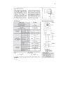
1.1
FYP1 Gantt chart
5
1.2
FYP2 Gantt chart
5
2.1
Example of AT Command
19
xi
LIST OF FIGURES
FIGURE NO.
TITLE
PAGE
1.1
Flowchart of the project
6
2.1
Toxic and Hazardous Waste Management Process
11
3.1
PIC 16F877A pin diagram
22
3.2
Figaro TGS 2600 Gas Sensor
23
3.3
Gas Sensor Circuit Connection
24
3.4
Standard Package of iTegno 3832 Modem
25
3.5
PIC Starter Kit SK40C
27
3.6
16x2 LCD
28
3.7
Schematic for LCD Connection
28
3.8
UART to RS232 Converter Schematic Diagram
29
3.9
UART to RS232 Converter
30
3.10
MicroC Pro Software Interface
31
3.11
PICkit 2 Programmer Software
32
3.12
Flowchart of GUI Application
33
3.13
COM port error message box
34
3.14
PIN error message box
34
3.15
Please Wait sign at connect button
35
3.16
Successful Connection message box
35
3.17
GUI Application Main Form
36
3.18
System Architecture
37
3.19
The mCoreLib.dll reference
38
3.20
The mCore.SMS library defined
38
3.21
Function to read message from mobile phone
39
xii
4.1
The Flowchart of the system
41
4.2
Sensor output before toxic detected
42
4.3
Sensor output after toxic detected
42
4.4
GSM Modem output before data is send
43
4.5
GSM Modem output when data is send
43
4.6
Message Box of GUI Application
44
xiii
LIST OF SYMBOLS AND ABBREVIATIONS
3G
-
Third Generation
A/D
-
Analog to Digital
AC
-
Alternate Current
ADC
-
Analog to Digital Conversion
AT
-
Attention
CO
-
Carbon Monoxide
COM
-
Communication Port
CPU
-
Central Processing Unit
DC
-
Direct Current
DLL
-
Dynamic-Link-Library
DOE
-
Department of Environment
EEPROM
-
Electrically Erasable Programmable Read Only
Memory
EQA
-
Environmental Quality Act
EXE
-
Running Executable Program
FYP1
-
Final Year Project 1
FYP2
-
Final Year Project 2
GDP
-
Gross Domestic Product
GPRS
-
Global Packet Radio Service
GPS
-
Global Positioning System
GSM
-
Global System for Mobile Communication
GUI
-
Graphical User Interface
HEX
-
Hexadecimal
I/O
-
Input Output
IC
-
Integrated Circuit
xiv
ICSP
-
In-Circuit Serial Programming
ID
-
Identification
LCD
-
Liquid Crystal Display
LED
-
Light Emitting Diode
M2M
-
Machine-to-Machine
MCU
-
Microcontroller
MHz
-
Mega Hertz
OOP
-
Object Oriented Programming
PDU
-
Protocol Data Unit
PIC
-
Peripherals Interface Controller
PIN
-
Personal Identification Number
ppm
-
Part Per Million
RAM
-
Random Access Memory
RFID
-
Radio Frequency Identification
RL
-
Load Resistor
ROM
-
Read Only Memory
SIM
-
Subscriber Identity Module
SMS
-
Short Message Service
UART
-
Universal Asynchronous Receiver/Transmitter
UCS2
-
2-byte Universal Character Set
USB
-
Universal Serial Bus
V
-
Volt
VC
-
Circuit Voltage
VH
-
Heater Voltage
WAP
-
Wireless Application Protocol
xv
LIST OF APPENDICES
APPENDIX
TITLE
PAGE
A
TGS2600 User Manual
50
B
PIC16F877A Source Code
52
C
Microsoft Visual Basic 2008 source code
56
ii
CHAPTER 1
INTRODUCTION
1.1
Background
Malaysia has achieved remarkable success in various sectors of development
especially in the manufacturing sector which experiencing tremendous rapid
proliferation. The nation economic growth spurred by the development of
manufacturing industries, proving that this sectors plays an important role in
ensuring that the nation economy is thriving constantly. In 2011, it is reported by the
Ministry of Finance that the manufacturing sector contributed RM 164.107 million to
Malaysia’s Gross Domestic Product (GDP), accounting for 27.92% of overall GDP
in 2011, with 6.7% growth over the previous year [2]. Due to this rapid
industrialisation, generation of toxic and hazardous waste have increased over the
years.
Over the years, Environmental Quality Act 1974 is an act which is used to
control most of the hazardous waste in Malaysia. Hazardous waste is subject to
some type of recovery (recycling) operation, burned in integrated waste management
centre incinerator, burned at local off-site clinical waste incinerators, transported to
off-site disposal facilities or disposed for onsite treatment [1]. Out of 77 waste codes
2
listed on the Environmental Quality (Scheduled Waste) Regulations 2005, only 15
waste codes are allowed to be sent to the waste recyclers [1].
The incidence of illegal dumping by the industries is due to the highly
expensive price of legal scheduled waste treatment. The waste generators have to pay
more to dispose their waste compare to recycle. This has caused the river to be
polluted by the industrial waste especially by toxic and hazardous waste. It was
reported that there is an average of 97 cases of illegal toxic waste disposals from year
2001 to 2006 [3]. Furthermore, only 40 cases of illegal hazardous waste dumping
have been successfully brought to court under Section 34(B) EQA 1974 and the rest
of the culprits were not traced [3].
Therefore this project is design to effectively detect the toxic and hazardous
waste that being disposed illegally by the industries to the river. A smart wireless
system is used using GSM as the transmitter and the receiver to send and receive data
from the detected location to the monitoring location. No matter where the location
of the toxic waste being disposes, the authorities will always be notified by the
system. Further action can be able to be taken on the party responsible and eventually
preventing water pollution from happening.
1.2
Problem Statement
The problem of illegal dumping of toxic waste into the river by the industry is
nothing new to the public. This problem often occurs, especially when it rains or
rainy season. The industry will open up the toxic storage tank to dispose the toxic
waste into the river.
3
This toxic waste will be channelled through the drain and eventually down
into the nearby river. The strong river currents due to the rain will carry away the
toxic waste being dumped. This results in the industry to escapes from any legal
action because there is no evidence to show that they the one who dispose the toxic
and hazardous waste into the river.
An effective and reliable wireless system is needed to detect the illegal
disposal of toxic waste into the river by the industries. The system should be able to
report the exact location of the incident to the authorities as soon as the toxic being
dumped.
1.3
Objectives
The objectives of this project are as follows:
1. To reinforce capacities to detect and halt any illegal attempt by the
industries to introduce toxic and hazardous substances into the river.
2. To meet the goals of eco-friendly development.
3. To avoid environmental pollution and adverse health effects due to the
improper disposal by industries.
1.4
Scope of Project
To ensure that every objective outlined in the project can be implemented
successfully, two types of scopes have been emphasized. Distribution of the two
4
scopes of this project is formulated to design of hardware and software design. For
hardware, it can be categorized into three systems, namely:
1. PIC 16F877A Microcontroller
2. The sensing system
3. The wireless system
The system consists of an electrochemical gas sensor. It is used to detect the
presence of toxic gas from the toxic waste being disposed while the wireless system
consists of GSM Modem and a mobile phone to transmit and receive data.
There are two parts that require software design:
1. Microcontroller (PIC16F877A) Programming.
2. Monitoring System
MicroC PRO and PICkit 2 is used to write the c programming and program it
into the PIC16F877A respectively while Visual Basic 2008 is used to create GUI
application for the monitoring system.
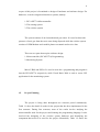
1.5
Project Planning
The project is being done throughout two semester period continuously.
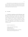
Table 1.1 show the detail of works for the project that has been implemented in the
first semester. During first semester, most of the works involve studying the
microcontroller used for the project and learning the programming language. It also
involved the designing of the wireless system hardware and identifying the
component that need to be used for the project. Meanwhile, Table 1.2 shows the
5
works done during the second semester. The second semester is spent to complete
the whole project including the programming and the hardware completion. Testing
and analysis of the completed system are also conducted in the second semester
before thesis writing is done.
Table 1.1: FYP1 Gantt chart
Table 1.2: FYP2 Gantt chart
6
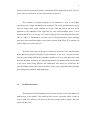
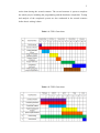
1.6
Methodology
Figure 1.1: Flowchart of the project
The first method for the project development is getting the project title and
objectives. After knowing about what project to develop for the final year project, the
first thing that needs to be done is to find the most suitable title for the project. A
good title can give a good impression on the project to be developed as a whole.
Then the objectives of the project were found to increase the chances of leading to a
specific outcome.
The next step is conducting literature review and writing the project proposal.
All the information needed to complete the project is gathered and study by
reviewing all journals, articles, books and previous research that related to this
project. The internet also is used as one of the sources to find the most suitable
wireless system that can be implemented in the project. After taking into account all
7
the factors that lead to the success of this project, GSM is selected as the most
suitable system. The project proposal was later prepared in preparation for the
beginning of the project.
Hardware research is done next to increase the understanding of every
component, tools and instruments that will be used for the project including the
sensor, PIC microcontroller and wireless GSM Modem. On this part, the proposed
system is design, reviewed and understood more deeply in order to facilitate the
future installation work. Software research is also similarly done to increase the
understanding and avoid many mistakes during the programming process.
On the implementation of hardware and software part, after purchasing all the
components for the project, the project development will preceded by installing the
hardware according to the designed system. All the software will also be
implemented to control the system and to create the project GUI eventually to
complete the project.
The most important stage to ensure the success of the project is the final
methodology which testing of hardware and software. The system will be tested on
its effectiveness and any hardware or software errors will be repaired and improved
to enable the project worked as well as it has been proposed. After completing all the
processes, the project is ready and prepared to be use in the detecting of illegal toxic
waste disposal by the industries.
8
1.7 Thesis Outline
This thesis consists of five chapters. Chapter 1 covers the project background,
problem statements, objectives, project scope, project planning and methodology.
Information collected throughout the two semesters for the project from literature
review is written out in chapter 2. Chapter 3 explains the development of the project
system. The project system combines the software and hardware of the entire project.
Then, chapter 4 will concern about the result obtain from the test conducted and
discussions of the analysis while the project conclusions and recommendation will
wrap up in the final chapter.
9
CHAPTER 2
LITERATURE REVIEW
2.1
Literature Background
Literature review was carried out throughout the whole project to gain
knowledge and skills needed to complete this project. The main sources for this
project are the previous project and research thesis that is related to the project and
the other sources are books, journals and articles obtained from the internet. So this
chapter discusses the projects and thesis related to this project.
By reviewing the previous works, research and projects, there are some ways
and features that can be applied and added to ensure the project success. Theories
and the knowledge related also are the important matter needed to develop this
project. It has been acquired and carried out to achieve the objectives of this project.
Thus the books, journals and articles are the most accurate source for it.
10
2.2
Toxic Waste
According to the definition outlined by the Occupational Safety and Health
Act 1994, toxic intended as substances and preparations which if inhaled or digested,
or penetrate the skin can cause serious health risks or death if it is ingested or enter
the respiratory tract and skin contact with humans. Toxic is any waste in the form of
liquids, solids or gases which may have adverse effects on human health, animals
and the environment in general. Toxic levels of a substance to be determined by a
laboratory test called the Toxicity Characteristic Leaching Procedure (TCLP).
Toxic materials contain carcinogens. This material may increase the chance
of a person to get cancer. Toxic substances are released by industrial activities such
as disposal of radioactive materials by nuclear plants, garbage from the residential
areas, heavy metals from industrial plants and residues of herbicides or pesticides
from agricultural activities.
2.3
Toxic and Hazardous Waste Management in Malaysia
The control of dangerous toxic and hazardous waste can be done
comprehensively with the facilities and technologies provided. Malaysia uses a
variety of ways of disposing or treat dangerous toxic waste that are generated such as
the use of sanitary landfills, incinerators, physical and chemical treatment and
stabilization. The process of toxic and hazardous waste management is shown in the
Figure 2.1. All waste generated by industries will be classified before transportation
process can be performed. Some of the toxic and hazardous waste will be delivered
to recovery and treatment facility while the other half will be transported directly to
the grave facilities for disposal.
11
Figure 2.1: Toxic and Hazardous Waste Management Process
The largest center for the management of toxic and hazardous waste in
Malaysia is the Integrated Hazardous Waste Treatment Plant located at Bukit Nanas
Negeri Sembilan manages by Kualiti Alam. This center covers the entire process of
waste management starting from collection of waste from generators, transportation,
and treatment up to disposal. It has the facilities for high temperature incineration,
physical and chemical treatment, stabilization and secure landfill. Most of the toxic
and hazardous waste in Peninsular Malaysia are managed by this facility.
12
2.4
Cause of Water Pollution in Malaysia
Water pollution is a pollution that occurs in rivers, lakes and sea. The main
sources of water pollution in Malaysia are such littering from residential areas along
rivers, lakes and sea side. Water pollution can be categorized or arising from fixed
sources and the not fixed (non point) source. The causes of fixed sources include
sewage treatment plants, industrial manufacturing, agro-based industries and animals
farms. The cause of not fixed (non point) is defined as the resources that are not
derived from one discharge point.
In 2007, the Department of Environment (DOE) has recorded a total of 19320
causes of water pollution. They comprised of sewage treatment plant of 9337
(48.3%), including 640 network pumping stations, manufacturing industries 8708
(45.1%), animals farms and agriculture-based industries 779 (4.0%) and 485 (2.5%)
respectively. Disposal of toxic waste along the river by factories also a source of
water pollution in Malaysia. Toxic waste is discarded and passed into the drains,
ditches, canals and into the river.
DOE has collected statistics on the causes of water pollution from the
manufacturing and agro-based industries via on site excursions and questionnaires.
The total amount of water pollution from both the industry is at 9204.
13
2.5
Current Technology used by Department of Environment
There are many technologies that can be used to enable detection of any
activity contrary to the law that affects the environment, especially in the detection of
illegal toxic waste disposal. The DOE in Malaysia has been using the E-Consignment
Note system to observe the disposal of wastes so that it is being properly managed.
2.5.1 E-Consignment Note System
In order to ensure efficient and safe management of the scheduled wastes and
to monitor the generation and disposal of toxic waste, Department of Environment
uses E-Consignment Note system. DOE starts to enforce E-Consignment Note
system beginning on January 2007 to insert the consignment note of the scheduled
wastes information by using the email facility. All manufacturers of scheduled
wastes, transport contractors and recipients of the scheduled wastes are required to
use this system for every movement of the scheduled wastes.
E-Consignment Note shall provide reports generation of scheduled wastes
through the web as prior notification to the DOE if there are any generation of
scheduled wastes by the premises. Through this system, the DOE only required to
obtain reports generation of scheduled wastes from E-Consignment web applications
without having to go to the affected premises. DOE can identify any environmental
problems that arise by a surprise visit to a particular premise identified to produce the
scheduled wastes by making a comparison between the wastes declared and the
wastes available at the premises.
14
2.6
Previous Related Projects
To ensure that this project solved the described problem statement, the
previous projects have been used as references. The reason that the previous projects
are referred to is to learn and improve all the advantages and disadvantages of all
these projects. Any problems encountered by the previous projects will successfully
avoided in trying to develop the current project.
2.6.1 Toxic Gas Release Alarm System Using PIC Microcontroller by
ZARITH SOFIA SURAYA BT HJ BAKERI [5]
This project was created to solve the problem that occurred from the carbon
monoxide gas released by motor vehicles and other gasoline powered tools, heaters,
and cooking equipment that is dangerous to human health by detecting the gas using
TGS 2442 gas sensor and generate an alarm signal when the detected gas reach its
hazardous level. Powered by Microchip’s PIC18F2550, this project enable users not
only be alarmed when the carbon monoxide gas reach a dangerous level but also to
be aware of the gas concentration level which will be displayed on the system’s
LCD. Built using a latest carbon monoxide sensor TGS 2442, the system can detect
up to 1000 ppm of carbon monoxide level. The alarm signal system consists of
LEDs, LCD and buzzer which will triggered according to the gas concentration level
detected by the sensor.
This project limitation is that it’s only detected carbon monoxide gas in
residential area and signals the alarm system to the nearby people. The system also
does not report the occurrence of dangerous volume of the toxic gas emission to the
authorities for further action.
15
2.6.2 Smart Management Parking System by MOHD FANDY BIN YA
RAHIM [6]
This project is about the management of parking system services. Smart
management parking system is developed to optimize the parking system so that it
will be more users friendly. The objective of this system is to introduce the old
system into the new system by upgrading new technologies. The new technologies
are using reservation parking space and by knowing the information parking space
available. The technologies that will be use in this project are the Short Message
Service (SMS) system integrated with the new microcontroller. The project also
include the GUI technologies develop by using the Visual Basic 6.0 to control the
system of the project in the control room.
This project is using GSM technology to communicate between user and the
control room. The GSM technology can be implemented in the industrial illegal toxic
waste disposal via smart detection system project for wireless communication. The
technology is modified so that the data will automatically be send through a GSM
Modem and receive by a mobile phone act as a modem that will be represented on
the monitoring system.
2.6.3 Smart Communication Using Radio Frequency Identification and GPRS
Modem by MOHAMAD SAIFUL ISLAM BIN AZIZ [7]
This project presented about teachers and parents wireless communication
using Global Packet Radio Service (GPRS) Modem and Radio Frequency
Identification (RFID) when there is an emergency appears towards their children in
school. The purpose of this project is to invent a cost effective communication
system by using RFID technology and GPRS. This project consists of 125 kHz
16
passive RFID/ID tag that will read by RFID reader and GPRS modem send a SMS
message to parents. Both RFID reader and also GPRS modem will be controlled by
microcontroller that acts as a ‘brain’ for the whole system. Parents will receive a SMS
message about the situation of their children at pre-school as the passive RFID/ID tag
has been read by RFID reader.
The wireless communication of this project is studied and then implemented to
the development of industrial illegal toxic waste disposal via smart detection system
project. The way RFID triggered the GSM to send SMS is slightly replicate in gas
sensor and GSM interface of this project.
2.7
Summary of Previous Related Projects
Each of the previous projects related to the projects to be developed are
reviewed and taken into consideration. All of these projects have it own advantages
and disadvantages that can be highlighted to the use of Illegal Industrial Toxic Waste
Disposal via Smart Detection System. Although previous projects have different
objectives, every project is viewed in terms of technology used. For example, gas
detection project using gas sensor. A similar technology is used to detect toxic waste
for the projects to be developed, but with different applications.
GSM technology used by the previous project also learned and considered
carefully so that it can be applied more effectively in ensuring that illegal dumping of
toxic waste can be reported to the relevant authorities. Display method used by one
of the previous projects also applied with a more convenient and simple approach to
establish a user friendly advantage for the project to be developed.
17
2.8
Short Message Service (SMS)
Short Message Service (SMS) is a communications service that uses
standardized communication protocol. It allows the exchange of text messages which
involves one mobile phone to another mobile phone. With an estimated of 2.4 billion
active users using SMS services via their mobile phones, SMS is an application data
that most widely used in the world. SMS technology used today has greatly assisted
in the advancement and the growth of communication systems in the world.
SMS in the first place is designed as part of the GSM, but is currently
available on various networks, including 3G networks. However, not all text
messaging systems use SMS. An SMS consist a maximum of 140 bytes (1120 bits)
of data that is 160 characters when the 7-bit character encoding is used. The 7-bit
characters are suitable for encoding Latin characters like English letters.
Furthermore, one SMS may also include up to 70 characters if 16-bit Unicode UCS2
character encoding is used. Almost all wireless carriers provide a cheap SMS
message services. Unlike SMS, not all mobile phone models provide mobile
technologies such as WAP and Java.
2.9
Electrochemical Gas Sensor
The electrochemical sensors have been widely used in the chemical and
biomedical sensing element as a whole or part. Electrochemical sensor can generally
be split into the conductivity/capacitance, potentiometric, amperometric and
voltammetric sensors. The amperometric and voltammetric sensors are characterized
by their current-potential relationship with the electrochemical system and are less
well-defined. Amperometric sensors can also be viewed as a subclass of
voltammetric sensors.
18
Electrochemical sensor used an arrangement of two or three electrochemical
cell. For the purposes of measurement, the electrochemical sensors may be made in
steady state or transient. To increase the sensor selectivity and sensitivity, the mode
of operation determined will be adjusted. This will cause the current or potential for
the electrochemical sensor will show various values.
2.10
AT Command
AT command is the command uses to control the GSM modem or mobile
phone to perform task for example SMS sending or phone calling. Dial modems,
mobile phones and GSM modems support a common set of AT commands standard.
AT commands is developed from Hayes command set which is function as a based
messages exchanged between applications in order to manage GSM related events or
services. AT command works as a language for GSM modem to schedule a
command, a script, or a program to run at a specified date and time and as command
to view existing scheduled tasks. The main application for the extended AT
commands are to managing SMS transmission, monitoring the signal strength and
view phone book entries.
Extended AT commands allow us to:
1. Reading, writing and deleting SMS messages.
2. Sending SMS messages.
3. Monitoring the signal strength.
4. Monitoring the charging status and charge level of the battery.
5. Reading, writing and searching phone book entries.
19
Table 2.1: Example of AT Command
AT+CGMI
Manufacture Identification
AT+CGMM Request model identification
AT+CGMR Request revision identification
AT+CGSN
Product serial number
ATD
Dial command
ATH
Hang-Up command
AT+CMGF
Preferred message format
AT+CMGS
Send message
The AT command can be write and tested through the hyperterminal. Before
the writing of AT command, the mobile has to be test in order to determine which
type of SMS mode it is supporting. The SMS mode is divided into 2 types, one is
called PDU mode and another is called text mode. For PDU mode, the message
content that wish to send has to be converted to HEX code before sending process is
made. For text mode, SMS can simply be the alphabet format that is written
normally. There are also mobile phones that support type of SMS mode. Therefore
it’s easier if mobile phone that supports both modes is used
2.11
Microsoft Visual Basic 2008
Roughly there are hundreds of programming languages adopted by
programmers today, either amateur or professional. Every language is applied to
solve all sorts of problems. Language which is considered as procedures such as
BASIC, C, COBOL, FORTRAN, and Pascal can be classified as original or
traditional language. It is the language of procedures because the program that
determines the correct sequence for all operations. Further instructions for
20
implementation will be determined by the program logic in respond to condition and
user demand.
C++, C# and Visual BASIC is a new programming languages using two
different approaches such as object oriented (OOP) and event-driven programming.
Microsoft Visual Basic refers to event-driven a programming language that has many
elements of object-oriented language like Java. In an event-driven model the
program is not in accordance with a logical sequence. The sequence of execution do
not need be controlled and determined in this case.
In accordance with the transition of the world to graphical user interface
(GUI), Visual Basic is one of the languages that led to the transition. Visual Basic
was designed to enable programs to be carried out under windows without any
complexity generally associated with the programming window. Designed screen can
held standard window buttons such as command buttons, check boxes, selection
buttons, text boxes, and so forth. Every object of this window operates as predicted,
resulting in a window "standard" user interface.
21
CHAPTER 3
DEVELOPMENT OF SYSTEM
3.1
Hardware Development
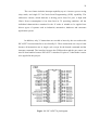
3.1.1 PIC Microcontroller 16F877A
PIC
is
referred
to
“Peripherals
Interface
Controller”.
16F877A
microcontroller has been selected for the development of the project. The PIC was
chosen based on functions required for the system usage. The IC chip having
internal-built-in ADC (Analog to Digital Conversion) and UART function. Gas
sensor used in this project produced output in analog values. Therefore, function of
the ADC must be adopted for the conversion from analog values to digital values due
to the nature of the microcontroller that can only receive digital value, either 1 or 0.
It utilizes two types of memories which are program memory and data
memory as internal memories. A share of 14.3 Kbytes (8192 words) consisting of
flash memory, and memory data contained in the program memory. Data memory
has two sources of data memory which 368-byte RAM (random access memory) and
256-byte EEPROM (electrical erasable programmable ROM).
22
The core feature includes interrupt capability up to 14 sources, power saving
sleep mode, and single 5V In-Circuit Serial Programming (ICSP) capability. The
sink/source current, which indicates a driving power from I/O port, is high with
25mA. Power consumption is less than 2mA in 5V operating condition. All the
individual characteristics contained in the IC make it suitable to be applied into
diverse types of systems such as industrial, automotive, hardware and consumer
application system.
In addition, only 35 instructions are needed to know by the user makes this
PIC16F877A microcontroller a user-friendly IC. These instructions are easy to learn
because all instructions are in single cycle except for the branch command and the
interrupt command. The interface between the GSM modem and the gas sensor can
also be done handier because PIC16F877A also has I/O pins of 33 that make it easier
to be applied in this project.
Figure 3.1: PIC 16F877A pin diagram
23
3.1.2 Figaro TGS 2600 Electrochemical Gas Sensor
Electrochemical gas sensors are the largest group of chemical sensors,
representing approximately 58% of the total. Electrochemical gas sensors have been
used extensively either as a whole or an integral part of a chemical and biomedical
sensing element. Electrochemical sensors are commonly used especially to detect
oxygen and toxic gases in the environment. Each of the sensors is specially designed
to only detect the gas that need to be detected.
This project uses Figaro TGS 2600 electrochemical gas sensor for the
detection of toxic waste which is on this case produces carbon monoxide gases for
the project development. This sensor has high sensitivity to a variety of air
contaminants gas, particularly to low concentrations gas contaminants such as
hydrogen and carbon monoxide (CO). Carbon monoxide is a gas that is colourless
and odourless which is produced by all internal combustion engines including diesel.
It is also produced from the burning of wood, paper or plastic products. The sensor
can also detect hydrogen at a few ppm levels. Compared with other sensors, TGS
2600 have a longer useful life and less costly. Figure 3.2 shows the Figaro TGS 2600
gas sensor
Figure 3.2: Figaro TGS 2600 Gas Sensor
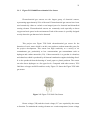
Heater voltage (VH) and the circuit voltage (VC) are required by the sensor
to function. To maintain the sensing element at a certain temperature, heater voltage
24
(VH) is required for the integrated heater. The measurement of output voltage (Vout)
is performed across the load resistor (RL) connected in series with the sensor. This
sensor has a polarity, so the DC voltage is required for the circuit voltage. The value
of load resistance chosen for this project is 47k ohms. Figure 3.3 shows the circuit
connection for gas sensor.
Figure 3.3: Gas Sensor Circuit Connection [12]
3.1.3 iTegno 3832 GSM Modem
GSM stands for Global System for Mobile communication. It is widely use as
the globally accepted standard for digital cellular communication. Cell phones
connect to it by searching for cells in the immediate vicinity. In order for GSM
Modem to operate, it needs a Subscriber Identity Module (SIM) card from a wireless
carrier. GSM modems convert digital data to Short Message Service (SMS)
messages for sending and receiving messages over the wireless network.
There are many different type of GSM modem that can be use in the market
today. In this project, the iTegno 3832 GSM modem is used as a transmitter for the
wireless communication. It is specifically ideal for reliable communication over
25
GPRS and GSM for corporate and industrial usage and can be deployed in various
Machine-to-Machine (M2M) applications.
This modem has many advantages that will benefit consumers, particularly in
the industries. One of the advantages is that it has a wide selection of interface which
is designed so that it can provide connectivity to any application of machine-tomachine (M2M). In this case, the project use RS232 interface to facilitate
communication between the microcontroller and the modem. Another advantage of
this modem is that it has an external antenna where this features can improve the
sensitivity and flexibility for industrial aid application for installation in remote
areas. [14] The modem is free from battery supply demand because power is
supplied from external power source which is AC supply thus it maintains a process
without interference with other power supply from other circuit and components.
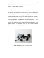
Figure 3.4 shows the standard package of iTegno 3832 modem.
Figure 3.4: Standard Package of iTegno 3832 Modem
26
3.1.4 Mobile Phone
The project uses GSM technology which is widely used in today mobile
phones. Mobile phones work by connecting to a wireless communication network
provided by mobile phone operators via radio waves or satellite transmissions. A
mobile phone is needed as a receiver for the system connected to a computer to
complement the wireless communication. A wide range of mobile phones can be
applied to this project as long as the phone inbox message can be accessed. A
Samsung Galaxy ACE is used as a GSM receiver to receive all the SMS sent to the
monitoring location.
3.1.5
SK40C
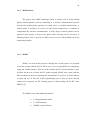
SK40C was used in this project to simplify the overall system. It is designed
as an easy-to-start solution for PIC MCU users. Users can install the I/O components
using any suitable manner. This kit comes without the PIC microcontroller to give
freedom for the user to select the PIC model required. SK40C also comes with the
basic elements for the user initiating the development of a project. It offers features
of plug and use. It also has ICSP programming port so that it can be directly
connected to computer for PIC burning process without taking off the PIC from
SK40C.[15]
The SK40C come with additional features:
2 x Programmable switch
2 x LED indicator
20MHz crystal oscillator
27
UART communication
USB on board.
Both switch connected to RB0 and RB1 on the SK40C are used in this project
with include the RESET switch for resetting the system. The UART communication
or Tx and Rx pin of SK40C that are connected to RC6 and RC7 respectively are also
used for PIC and GSM communication. Figure 3.5 shows the SK40C.
Figure 3.5: PIC Starter Kit SK40C
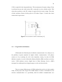
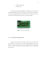
3.1.6 16x2 Liquid Crystal Display (LCD)
Liquid crystal display shown in Figure 3.6 functions as the output of the
microcontroller. It is used to display a word or number depending on project needs.
Value of 2 for 2x16 means two lines that can be displayed (the word or number),
while 16 denotes the number of data pins which is used to interface the
microcontroller.
28
Figure 3.6: 16x2 LCD
For this project, LCD is connected to SK40C to display the percentage of
output voltage when toxic waste is detected. It also shows the user the operating
status of the system. The LCD uses low power and makes it easy for interface
between the PIC microcontrollers. Figure 3.7 shows the connection between SK40C
and LCD.
Figure 3.7: Schematic for LCD Connection
29
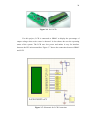
3.1.7 UART to RS232 Converter
PIC Microcontroller used UART signal while GSM Modem used RS232
signal. RS232 signal voltage is -15V to +15 V while the UART signal voltage is 0V
to 5V. Logic high or '1' for RS232 is -15V to-3V, logic low or '0' for RS232 is 3V to
15V. Logic high or '1' for the UART is 2V to 5V while logic low or '0' for the UART
is 0V to 0.8V. The difference signals used by the two devices caused it to be not
applicable for a direct connection. To overcome this signal inequality, a UART to
RS232 converter is used for this project.
The main component of the UART to Serial converter circuit is MAX232.
MAX232 is the chip that is used to connect between RS232 and UART signals.
MAX232 has a 16 pin and the input voltage is 5V. MAX232 has two sets of
UART/RS232 converter. [16] Pin 11 and 10 are input UART or UART transmit, pins
14 and 7 are output RS232 or RS232 receive. Pin 12 and 9 is the output UART or
UART receive, 13 and 8 pin RS232 or RS232 input is transmit. The schematic circuit
for UART to RS232 converter and the actual circuit are shown in Figure 3.8 and
Figure 3.9 respectively.
Figure 3.8: UART to RS232 Converter Schematic Diagram
30
Figure 3.9: UART to RS232 Converter
3.2
Software Development
3.2.1 PIC Microcontroller Programming
There are two essential processes for the PIC microcontroller programming
process which are to write a program and burn it into the microcontroller IC. After
the PIC program is written and successfully compile, the program was burned into
the microcontroller IC using the PICkit 2 software.
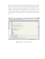
3.2.1.1 MicroC Pro
MicroC is a low cost C language compiler for PIC MCUs. It is optimized for
the limited and specialized environment for the embedded microcontrollers. Its
31
purpose is to provide the developer or programmer with the easiest ways to develop
applications for embedded systems by providing the same performance or outcomes.
MicroC is portable and was design to supports many CPU architecture. MicroC is
supplied as a Developer's Kit with everything you need to develop for a C and
assembly language software for a particular CPU. This software is used to create the
system program in C language. Figure 3.10 shows the software interface of MicroC
Pro.
Figure 3.10: MicroC Pro Software Interface
32
3.2.1.2 PICkit 2
Microchip Technology created PICkit 2 as a programmer for PIC
microcontrollers. PICkit 2 software is used to burn the hex file of the programming
into the PIC 16F877A. It supports a maximum of 4M bytes of memory for
programmer-to-go feature.
Figure 3.11: PICkit 2 Programmer Software
3.2.2 GUI Application Programming
In order to obtain a good result on the location of monitoring, GUI
application is very important for the whole system for this project. This application
was developed using Visual Basic 2008.
33
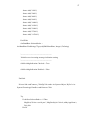
3.2.2.1 Microsoft Visual Basic 2008
Visual Basic is a very well known language in the commercial world. It is
because it allows the programmer to develop a Windows-based program with a
simple and rapid pace. Visual Basic programmer can add a large amount of code just
by dragging and dropping controls, like the buttons and the dialog boxes, and later
determine the appearance and behaviour. Each of these windows objects produces a
standard user interface that makes the program becomes user friendly. This language
not only enables programmers to develop simple GUI applications, but also complex
applications.
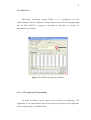
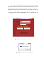
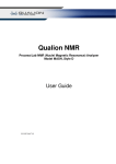
Figure 3.12 shows the flowchart for the GUI application located at the
monitoring location developed using Microsoft Visual Basic 2008. When the
application is run, the user must select the correct communication (COM) port and
baud rate of the connected mobile phone. The user can obtain this information by
accessing the device manager of the computer.
Figure 3.12: Flowchart of GUI Application
34
Every computer today is developed with a COM port or known as the serial
port. It is an I/O port that is used by computers to produce asynchronous
communication between serial devices or in this case a mobile phone and computers
with the ability to send and receive data. Baud rate can be interpreted as transmission
speed or rate of the number of symbols per second sent and received between two
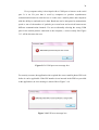
different communication channels. If a user accidentally selecting the wrong COM
port for the mobile phones connected to the computer, a screen exactly like Figure
3.13 will be shown to the user.
Figure 3.13: COM port error message box
For security reasons, the application also required the correct mobile phone PIN code
before it can be applicable. If the PIN number is not inserted in the PIN box provided
in the application, an error message is shown like in Figure 3.14.
Figure 3.14: PIN error message box
35
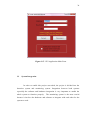
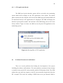
After the three conditions are satisfied and the connect button is clicked, the
application will show “Please Wait” at the connect button indicate that the computer
and mobile phone communication is being processed as shown in Figure 3.15.
Eventually the mobile phone will be connected successfully with the GUI application
while connection will fail if contrary. A message box will appear as shown in Figure
3.16 when a successful connection has been made. Figure 3.17 shows the main form
for the GUI application.
Figure 3.15: Please Wait sign at connect button
Figure 3.16: Successful Connection message box
36
Figure 3.17: GUI Application Main Form
3.3
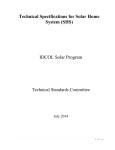
System Integration
In order to enable this project succeeded, the project is divided into the
detection system and monitoring system. Integration between both systems
especially the software and hardware integration is very important to enable the
whole system to function properly. The monitoring system is the most crucial
because it involves the hardware and software to integrate with each other for the
system to work.
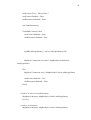
37
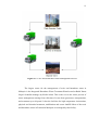
Figure 3.18: System Architecture
3.3.1
Mobile Phone with Visual Basic 2008
The monitoring system demand mobile phone with Visual Basic 2008
interface. This interface is performed by using a dynamic-link-library (DLL) that act
as a reference for Visual Basic 2008. A dynamic-link-library (DLL) is a collection of
small programs, which can be called upon when needed by the running executable
program (EXE). The DLL lets the program to communicate with a specific device
connected to the computer COM port to do a particular function. This project uses
the mCoreLib.dll as reference file.
The mCoreLib.dll is an ActiveX SMS Component that will enable
applications to send and receive SMS with robust and user friendly advantages. It
can be used with any GSM modem or mobile phone connected to the computer COM
port using a data cable. The mCoreLib.dll reference is add in Visual Basic 2008 as
shown in Figure 3.19
38
Figure 3.19: The mCoreLib.dll reference
Once the reference has been set up on the DLL file, the declaration must
be
defined.
Figure
3.20
shown
the
functions
are
then
similar
to
System.IO.Ports.SerialPort but the manufacturer replaced the name as mCoreSMS.
The new message received is retrieved by using a special function by mCoreSMS
and display in a message box. Figure 3.21 shows the function used to display the new
incoming message. Functions e.Phone, e.TimeStampRFC and e.TextMessage
displays the detection system phone number, date and time of report, and the factory
address respectively.
Figure 3.20: The mCore.SMS library defined
39
Figure 3.21: Function to read message from mobile phone
40
CHAPTER 4
RESULTS AND DISCUSSION
4.1
Background of Result
This chapter will be discussing on the results obtain from this project starting
from the detection system part which the electrochemical sensor and GSM modem to
the monitoring system part where the computer and mobile phone interface result is
discussed. All the result will be shown and the analysis will be discussed in detail.
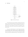
4.2
System Flowchart
The system flowchart is shown by Figure 4.1. The system will be installed near
the septic tank of the industry to make it easier to detect any disposal of the toxic
waste by the industry. When the industry tries to dispose the hazardous and toxic
waste to the river by channel it trough the drain, the electrochemical sensor will
sense the gas that released from the disposed waste. The GSM Modem then will send
the address location of the industry to another mobile phone. The mobile phone is
41
located at a monitoring system where the data collected will be displayed to the
authority. The authority next will taking on the role by going to the industry location
according to the address received by the system and take legal action against the
industry that commit the offense. The system then will be reset by the authority to
enable the system in normal condition.
Figure 4.1: The Flowchart of the system
42
4.3
Output of System
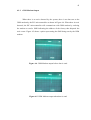
4.3.1 Sensor Output
The electrochemical sensor used in this project need at least +5V of voltage
input to be implemented properly. Wheatstone bridge principle is used in this sensor
to calculate the output voltage across load resistor. The output voltage of the sensor
in normal condition when there is no toxic gas detected is around +3.5V. It will then
increase rapidly when a toxic gas is detected. In this project, lighter which contain
butane gas is used as the toxic gas. The output before and after toxic is detected is
shown in Figure 4.2 and 4.3.
Figure 4.2: Sensor output before toxic detected
Figure 4.3: Sensor output after toxic detected
43
4.3.2 GSM Modem Output
When there is no toxic detected by the system, there is no data sent to the
GSM modem by the PIC microcontroller as shown in Figure 4.4. When there is toxic
detected, the PIC microcontroller will communicate with GSM modem by ordering
the modem to send a SMS indicating the address of the factory that disposed the
toxic waste. Figure 4.5 shows a pulse representing the SMS being sent by the GSM
modem.
Figure 4.4: GSM Modem output before data is send
Figure 4.5: GSM Modem output when data is send
44
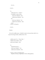
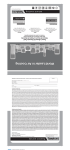
4.3.3 GUI Application Result
The SMS sent by the detection system will be received by the monitoring
system which will be display on the GUI application of the system. The mobile
phone connected to the computer will received the SMS being sent and the SMS will
be transferred directly to the application to be displayed. The SMS will display the
detection system phone number, date and time of the SMS being sent as well as the
factory address. Figure 4.6 shows the SMS received by the GUI application at the
monitoring system.
Figure 4.6: Message Box of GUI Application
4.4
Problems Encountered and Solution
There are several problems faced during the development of the project
including the software and hardware. The main problem encountered when attempt
to interface between the PIC microcontroller and the GSM modem failed. The GSM
modem does not send any response to the PIC microcontroller despite data from the
PIC accepted. This cause the sending of SMS when toxic gas detected failed to
45
occur. Another problem comes about when writing the program to create the GUI
application for the system. There is a problem to display and organize the received
SMS from the detection system into the application.
The former problem is solved by testing the UART to RS232 converter
circuit. The circuit is connected between the PIC microcontroller and a computer to
test whether there is data received or sent. After testing the converter circuit, it is
found that the converter circuit has connection error. Pin 7 and pin 8 of DB9
component of the converter circuit is shorted when in fact it should never have. The
mistake was corrected; afterward the PIC and GSM modem interface finally runs
smoothly. The later problem then solved by studying and understanding more about
ways to transfer the SMS received by the mobile phone to the GUI application for
viewing.
Another problem that plagued in the early development of this project is
when the mobile phone used as a receiver to receive the sent message at the
monitoring location cannot be accessed to read the message which came from the
detection system. Due to this, hyperterminal application is used to verify the
problem. After a closer investigation, it is founded that all new model of Nokia
mobile phones is not accessible to obtain or display all the messages received by the
phone. Eventually the problem is solved by changing the Nokia phone model to
another manufacturer model that provided access to its inbox message. All other
problems are also solved to make sure the project to be successful.
46
CHAPTER 5
CONCLUSION
5.1
Conclusion
Year after year, toxic wastes generation rate in Malaysia experienced a
significant increase in accordance with the increasing development of the industrial
areas. With the current trends of rapid population growth and industrialisation,
wastes and pollutants are released faster than the earth can absorb them, such that
maintaining a sustainable environment is becoming a challenging task. [4] Therefore,
the issue of illegal toxic waste disposal faced this day require a more efficient
settlement. Continuous surveillance against these illegal activities requires a robust
mobile system that has an immediate response with enough sensitivity as well as
long lifespan.
From the studies and research that have been taken in the development of the
project, it is concluded that the GSM wireless technology applied in the project can
provide a fast and effective way for sending and receiving data for the system
wherever the system is located. The project is replicating the normal way of
communicating with the authorities such as those used by police and fire department
before. The only different is the system automatically reports the case by SMS
immediately after toxic waste detected without depending on the user.
47
With the increasing cost to be incurred by the industries to dispose their toxic
waste in accordance to the law, most likely this illegal activity will be more prevalent
if not contained. This project will assist the authorities to detect any attempt to
dispose of toxic waste illegally by the industries with more fast and effective
approach. This project also succeeded in fulfilling every criterion needed to ensure
that every unlawful activity to dispose toxic waste by the industry can be traced.
5.2
Recommendation
To increase the capability of a product, continuous research and improvement
is needed to ensure the products remain competitive. Some improvements can be
made on this project to maximize its performance and overcome the limitations as
well as providing greater benefits to users. The industrial illegal toxic waste via
smart detection system can be enhanced by using GPS technology for its wireless
communication. This GPS technology will ensure that the location of illegal disposal
of toxic waste incident can be specified more accurate without requiring any use of
SMS to find out the address of the industries. Improvements are also needed in the
use of this project to allow only one system needed to detect illegal dumping of toxic
waste activities for the area around without requiring the installation of many similar
systems in one area.
48
REFERENCES
1. Abdul Rashid etc. ‘Illegal dumping of hazardous waste in Malaysia: assessing
based on implementation and compliance of environmental quality act (1974)
and the regulations’, Proceedings of 3rd International World Engineering
Congress, FIECC 2007, 2007.
2. Ministry of Finance Malaysia 2011 “Keluaran Dalam Negeri Kasar Mengikut
Jenis Aktiviti Ekonomi Pada Harga Malar 2000”,http://www.treasury.gov.my
/pdf/e konomi /le/1011 /jp2_3.pdf
3. Keng, L.H. ‘Scheduled waste management: regulations 2005’, Waste
Management Conference and Exhibition, ENSEARCH, Nikko Hotel, Kuala
Lumpur, 13–15 November, pp.1–7, 2006.
4. A. B. A. Z. A. Rashid, M. J. Aris, M. El-Harbawi, N. A. Rahman, A. M. Som,
"Hazardous waste management: current status and future strategies in
Malaysia," International Journal of Environmental Engineering, vol. 2, pp.
139-158, 2010.
5. Zarith Sofia Suraya Bt Hj Bakeri “Toxic Gas Release Alarm System Using
PIC Microcontroller”.2010 UTM Skudai Johor Bahru.
6. Mohd Fandy Bin Ya Rahim “Smart Management Parking System”.2010
UTM Skudai Johor Bahru.
49
7. Mohamad Saiful Islam Bin Aziz “Smart Communication Using Radio
Frequency Identification and GPRS Modem”.2011 UTM Skudai Johor
Bahru.
8. Joseph Wang, Kim Rogers (1995), Electrochemical sensors for
environmental monitoring: a review of recent technology, Las Vegas, USA :
U.S. Environmental Protection Agency.
9. Dogan Ibrahim (2001). PIC Basic: Programming & Projects. New York,
USA : McGraw-Hill Companies Inc.
10. Delphian Detection Technology “Sensor Technology –Electrochemical
Sensors”, http://www.delphian.com/electrochemical%20sensors.htm
11. Industrial Scientific “Electrochemical Sensors”, http://www.indsci.com/Elec
trochemicalSensor/
12. Figaro USA Inc., “TGS 2600 sensors datasheets and application notes”, 2009.
13. Wise Geek, “What is a GSM Modem”, http://www.wisegeek.com/what-is-agsm-modem.htm
14. iWOW Connections Pte Ltd. “iTegno 3832 GPRS Modem Hardware User
Guide”, 2008.
15. Cytron Technologies, “SK40C enhanced 40-pin PIC starter-up kit User’s
Manual”, Malaysia, 2009.
16. Texas Instrument, “MAX 232 DUAL EIA-232 DRIVERS/RECEIVERS”, 2004.
50
APPENDICES
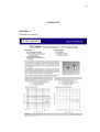
APPENDIX A
TGS2600 User Manual
51
52
APPENDIX B
PIC16F877A Source Code
#define SW1 PORTB.F0
#define SW2 PORTB.F1
//output
//LED
#define LED1 PORTB.F6
#define LED2 PORTB.F7
//LCD definition
sbit LCD_RS at RB4_bit;
sbit LCD_EN at RB5_bit;
sbit LCD_D4 at RD4_bit;
sbit LCD_D5 at RD5_bit;
sbit LCD_D6 at RD6_bit;
sbit LCD_D7 at RD7_bit;
sbit LCD_RS_Direction at TRISB4_bit;
sbit LCD_EN_Direction at TRISB5_bit;
sbit LCD_D4_Direction at TRISD4_bit;
sbit LCD_D5_Direction at TRISD5_bit;
sbit LCD_D6_Direction at TRISD6_bit;
sbit LCD_D7_Direction at TRISD7_bit;
//end port definition
//variable declaration
char txt[14];
char ptxt[14];
unsigned char enter = 0x0D;
unsigned long value, percent;
53
//end variable declaration
//function prototype declaration
void initialization(void);
void sms(char num[],char txt[]);
//end function prototype declaration
//starting main program
void main()
{unsigned char count=1;
initialization();
while(1)
{
count=0;
value=ADC_Read(0);
percent=((value*100)/1023);
IntToStr(percent,ptxt);
Lcd_Out(1,1,"");
Lcd_Out(2,4,ptxt);
if ((SW2==0)||(percent>85))
{
//delay_ms(2000);
while(SW1==1){
Lcd_Out(1,1," Report Sent ");
Lcd_Out(2,1,"Press SW1-Exit");
if(count<1)
{
54
sms("0175553152","41,Jln Tembaga 8,Tmn Industri,81300 Skudai Johor");
count=count+1;
}
}
Lcd_Cmd(_LCD_CLEAR);
}
//else{}
}
}
//initialization function
void initialization(void)
{
TRISA=0b00000001;
//tris port 1=input 0=output declare by
TRIS'port'=0b'port7-port0'
TRISB=0b00000011;
TRISC=0b10000000;
ADC_Init();
ADCON1=0b00001110;
Lcd_Init();
//initialization LCD
UART1_Init(115200);
PORTD.F3=PORTD.F2=PORTD.F1=PORTD.F0=0;
LED1=LED2=0;
Lcd_Cmd(_LCD_CLEAR);
//clearing LCD
Lcd_Cmd(_LCD_CURSOR_OFF);
55
UART1_Write_Text("AT+CMGF=1");
//initialize gsm to send sms by words
while(UART1_Tx_Idle() == 0);
UART1_Write(enter);
while(UART1_Tx_Idle() == 0);
delay_ms(150);
}
void sms(char num[],char txt[]){
UART1_Write_Text("AT+CMGS=");
UART1_Write(0x22);
UART1_Write_Text(num);
// send SMS
//"
// phone number to be sent
UART1_Write(0x22);
UART1_Write(enter);
delay_ms(1000);
// wait for gsm respons
UART1_Write_Text(txt); // text to be sent
UART1_Write(0x1A);
Lcd_Cmd(_LCD_CLEAR);
Lcd_Out(1,1," Sending SMS To ");
Lcd_Out(2,4,num);
delay_ms(3000);
Lcd_Cmd(_LCD_CLEAR);
}
// ctrl+z
56
APPENDIX C
Microsoft Visual Basic 2008 source code
Public Class frmMain
Private WithEvents objSMS As New mCore.SMS
Private strMyAppName As String = "Connection Status"
Private blnFormLoaded As Boolean = False
Private Sub frmMain_FormClosed(ByVal sender As Object, ByVal e As
System.Windows.Forms.FormClosedEventArgs) Handles Me.FormClosed
objSMS.Dispose()
objSMS = Nothing
End Sub
Private Sub frmMain_Load(ByVal sender As System.Object, ByVal e As
System.EventArgs) Handles MyBase.Load
Dim i As Integer
'-----------------------------------'Initialize COM Port DropDown List
'-----------------------------------cboPort.Items.Add("Select Port")
For i = 1 To 50
cboPort.Items.Add("COM" & i.ToString)
Next
cboPort.SelectedIndex = 0
'-----------------------------------'Initialize BaudRate DropDown List
'-----------------------------------With cboBaudRate
.Items.Add("110")
.Items.Add("300")
57
.Items.Add("1200")
.Items.Add("2400")
.Items.Add("4800")
.Items.Add("9600")
.Items.Add("14400")
.Items.Add("19200")
.Items.Add("38400")
.Items.Add("57600")
.Items.Add("115200")
End With
cboBaudRate.SelectedIndex =
cboBaudRate.FindString(CType(objSMS.BaudRate, Integer).ToString)
'--------------------------------------------------'Initialize new incoming message indication setting
'--------------------------------------------------chkNewMsgIndication.Checked = True
chkNewMsgIndication.Enabled = False
End Sub
Private Sub cmdConnect_Click(ByVal sender As System.Object, ByVal e As
System.EventArgs) Handles cmdConnect.Click
Try
If cboPort.SelectedIndex = 0 Then
MsgBox("Select a serial port", MsgBoxStyle.Critical, strMyAppName)
Exit Sub
End If
58
cmdConnect.Text = "Please Wait..."
cmdConnect.Enabled = False
cmdDisconnect.Enabled = False
SetCommParameters()
If objSMS.Connect() Then
cmdConnect.Enabled = False
cmdDisconnect.Enabled = True
objSMS.MessageMemory = mCore.MessageMemory.SM
MsgBox("Connection successful", MsgBoxStyle.Information,
strMyAppName)
Else
MsgBox("Connection error", MsgBoxStyle.Critical, strMyAppName)
cmdConnect.Enabled = True
cmdDisconnect.Enabled = False
End If
Catch ex As mCore.GeneralException
MsgBox(ex.Message, MsgBoxStyle.Critical, strMyAppName)
Exit Try
Catch ex As Exception
MsgBox(ex.Message, MsgBoxStyle.Critical, strMyAppName)
59
Exit Try
End Try
Try
cmdConnect.Text = "Connect"
If objSMS.IsConnected Then
cmdConnect.Enabled = False
cmdDisconnect.Enabled = True
Else
cmdConnect.Enabled = True
cmdDisconnect.Enabled = False
End If
Catch ex As Exception
End Try
End Sub
Private Sub cmdDisconnect_Click(ByVal sender As System.Object, ByVal e As
System.EventArgs) Handles cmdDisconnect.Click
cmdDisconnect.Text = "Please Wait..."
cmdDisconnect.Enabled = False
cmdConnect.Enabled = False
Try
objSMS.Disconnect()
cmdConnect.Enabled = True
cmdDisconnect.Enabled = False
Catch ex As mCore.GeneralException
MsgBox(ex.Message, MsgBoxStyle.Critical, strMyAppName)
60
Exit Try
Catch ex As Exception
MsgBox(ex.Message, MsgBoxStyle.Critical, strMyAppName)
Exit Try
End Try
cmdDisconnect.Text = "Disconnect"
End Sub
Private Sub objSMS_NewMessageReceived(ByVal sender As Object, ByVal e As
mCore.NewMessageReceivedEventArgs) Handles objSMS.NewMessageReceived
'New Message Indication Event
'Display the new message
My.Computer.Audio.Play(My.Resources.Siren_Wav____MP3_Sounds,AudioPlayM
ode.Background)
MsgBox("FROM: " & e.Phone & vbCrLf & vbCrLf & "DATE/TIME: " &
e.TimeStampRFC & vbCrLf & vbCrLf & "FACTORY ADDRESS" & vbCrLf &
e.TextMessage, MsgBoxStyle.Information, "NEW MESSAGE RECEIVED...")
Control.CheckForIllegalCrossThreadCalls = False
Control.CheckForIllegalCrossThreadCalls = True
End Sub
Public Sub SetCommParameters()
'Set communication parameters
'check if port is already connected
Try
If Not objSMS.IsConnected And cboPort.SelectedIndex > 0 Then
objSMS.Port = cboPort.Text
61
objSMS.BaudRate = CType(CInt(cboBaudRate.Text), mCore.BaudRate)
objSMS.DataBits = mCore.DataBits.Eight
objSMS.Parity = mCore.Parity.None
objSMS.StopBits = mCore.StopBits.One
objSMS.FlowControl = mCore.FlowControl.RTS_CTS
objSMS.PIN = txtPIN.Text
End If
Catch ex As mCore.GeneralException
MsgBox(ex.Message, MsgBoxStyle.Critical, strMyAppName)
End Try
End Sub
Private Sub chkNewMsgIndication_CheckedChanged(ByVal sender As
System.Object, ByVal e As System.EventArgs) Handles
chkNewMsgIndication.CheckedChanged
Try
chkNewMsgIndication.Enabled = False
SetCommParameters()
objSMS.NewMessageIndication = chkNewMsgIndication.Checked
Catch ex As mCore.GeneralException
chkNewMsgIndication.Checked = objSMS.NewMessageIndication
Exit Try
62
Catch ex As Exception
Exit Try
End Try
chkNewMsgIndication.Enabled = True
End Sub
End Class