1
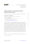
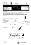
mod
Dual Contour User Guide
Discrete Transistor Envelope Generators
Thank you for purchasing the AJH Synth MiniMod Dual Contour module, which like all AJH Synth
Modules, has been designed and handbuilt in the UK from the very highest quality components.
We hope that it will help and inspire you towards creating some great music and soundscapes!
It comprises two independant Envelope Generators in a single 12hp wide Eurorack module.
These are very accurate replicas of the vintage Model D Contour Generators, with identical all
transistor EG circuitry, using the correct +9.3V and -10v supply voltages of the original. This
ensures that they exactly replicate the original envelope response, along with all of the associated
eccentricities. Extra features include manual trigger buttons and envelope status LED’s.
There are two factors that are absolutely essential when attempting to faithfully recreate the
iconic Model D envelope behaviour and function, firstly the very fast exponential slope , which
when used in conjunction with the (near) linear slope of the original VCA is largely responsible
for the famous Model D “punch”. Secondly, the re-trigger behaviour is quite unique; multiple
retriggering progressively increases the output level so that either the volume increases incrementally or the filter opens incrementally with each extra key press.
We have added independant Decay switches for each Contour Generator rather than the shared
switch of the original synthesiser, these switches change the Contour response from decay active
(switch down) to zero decay (switch up) when the gate signal goes low. The actual envelope
response is ADSD (Attack, Decay 1, Sustain, Decay 2), where Decay 1 and Decay 2 speeds are
always equal.
Module width is 12 HP of Eurorack space and it is compatible with standard Eurorack cases. The
height of the panel is 128.5mm and depth is 26mm . There are four mounting holes at the
corners of the module and we provide 4 of M3 rack fixing screws along with a Eurorack compatible power cable. Current consumption is 38mA from the +12V supply rail and 15mA from the
-12V supply rail.
All AJHSynth modules are covered by a one year guarantee against manufacturing defects.
Note:
It is very important that the power supply ribbon cable is connected correctly, see the “adjustment and
calibration” section for an illustration of the correct orientation.
www.ajhsynth.com
Controls, inputs and outputs
13
EG 1 Status Led
5
EG 1 Attack
11
EG 1 Decay Switch
mod
CONTOUR GENERATORS
ATTACK 1
600
ATTACK 2
1
200
600
200
5
10 ms
10 ms
10 Sec
600
EG 1 Decay
14
EG 2 Attack
6
EG 2 Decay
8
5
ENV 1
DECAY 1
7
1
EG 2 Status Led
10 Sec
DECAY 2
600
1
1
DECAY
200
200
5
5
EG 2 Decay Switch 12
ENV 2
9
10 ms
EG 1 Sustain
10 ms
10 Sec
SUSTAIN 1
4
10 Sec
SUSTAIN 2
4
6
EG 2 Sustain
10
EG 2 Man. Trigger
4
EG 2 Output
16
EG 2 Gate Input
2
6
DECAY
3
EG 1 Man. Trigger
2
8
0
10
2
8
0
TRIG
1
TRIG
EG 1 Gate Input
GATE 1
15
10
OUT 1
GATE 2
OUT 2
EG 1 Output
1 EG 1 Gate Input :
The Envelope Generator cycle of EG 1 is started (triggered) by a gate signal to this Input,
alternatively it can also be triggered using the EG 1 Manual Trigger switch (3). The
Eurorack standard gate voltage is + 5 Volts, however any voltage above +2V will trigger
the EG successfully and gate voltage levels up to +10V are acceptable.
2 EG 1 Gate Input 2 : This is the Gate Input for EG 2 and performs in the same manner as EG 1
3 EG 1 Man Trigger : Pressing this button triggers the Envelope Generator, sustain will be active for as long as
the button is held down - it is the equivalent of pressing a note on a keyboard.
4 EG 2 Man Trigger : This is the manual trigger button for EG 2.
5 EG 1 Attack :
Sets the speed of the attack cycle of EG 1, which can be varied from around 10 milliseconds to 10 seconds.
6 EG 2 Attack :
Sets the speed of the attack cycle of EG 2, which can be varied from around 10 milliseconds to 10 seconds.
7 EG 1 Decay :
Sets the speed of the decay cycle for EG 1, and can be varied from 10 milliseconds to 10
seconds. The decay cycle commences either when the attack reaches its maximum level
or the gate pulse ends, whichever happens sooner.
With the gate high (on) the envelope will decay down to the sustain level. Immediately
the gate goes low the decay recommences from the sustain level and decends down to
zero at the rate determined by the EG 1 Decay Control - see Fig 1.
8
EG 2 Decay :
Sets the speed of the decay cycle for EG 2, and can be varied from 10 milliseconds to 10
seconds. The decay cycle commences either when the attack reaches it’s maximum level
or the gate pulse ends, whichever happens sooner.
9
EG 1 Sustain :
Sets the sustain level, between 0 to 8 volts for EG 1. It is only active when the gate is high,
as soon as the gate goes low the decay cycle recommences.
10 EG 2 Sustain :
Sets the sustain level, between 0 to 8 volts for EG 2. It is only active when the gate is high,
as soon as the gate goes low the decay cycle recommences.
11 EG 1 Decay Switch :
With switch down the decay function is active on EG 1, when the switch is up the decay is
instantanious. This mimics the action of the Model D decay switch but we have added an
individual switch for each envelope rather than one switch which acts on both both.
12 EG 2 Decay Switch :
With switch down the decay function is active on EG 2, when the switch is up the decay is
instantanious.
13 EG 1 Status LED :
Gives a visual indication of the output level of Envelope Generator 1
14 EG 2 Status LED :
Gives a visual indication of the output level of Envelope Generator 2
15 EG 1 Output :
This is the output from EG 1, and is typically between 0 and 8 volts, however with multiple
retriggering the output can go as high as 11 volts. This is not a problem to the CV inputs
of the MiniMod VCF and the MiniMod VCA which can safely handle these signal levels,
however caution is advised when connecting to Eurorack modules from other manufacturers.
We have included jumpers on the pcb (J1 and J2) which when removed lower the
nominal output voltage from 8 volts to 5.5 volts and limit the peak signal to 8 volts.
Please note that this jumper should be removed if using with other modules unless you
are certain that the higher CV voltages can be safely accommodated.
16 EG 2 Output :
This is the output from EG 2, and the signal levels are identical to EG 1 (see above)
Single Trigger
Fast Multiple Retrigger
10v
Output Level
8v
6v
4v
Sustain Level
0 to 8 Volts
2v
0v
Attack Phase
Decay 1
Sustain
Decay 2
Always the same
rate as Decay 1
8v
Gate Signal
6v
4v
Gate On
2v
Gate Off
On
On
On
On
0v
Time
Fig. 1 - An Illustration of MiniMod Envelopes
Adjustment and Calibration
Note:
This information is given for completeness, the MiniMod Dual Contour Generator is calibrated
after manufacture and under normal circumstances should not require any user adjustment.
A EG 1 Offset
B
EG 2 Offset
C
EG 1 Level Out (J1)
Power Cable
D EG 2 Level Out (J2)
Red Stripe aligns with -12V as shown
A EG 1 Offset :
Sets EG 1 output offset voltage. A voltmeter accurate to 1mV or better is required to
adjust this trimmer.
To adjust: Connect the voltmeter to EG 1 Output. Turn decay switch on, set Attack,
Decay, and Sustain controls to 0. Measure the output voltage and carefully adjust
Offset Trimmer 1 until output voltage is less than +/- 40mV.
B EG 2 Offset :
Sets EG 2 output offset voltage. The calibration process is the same as that for EG 1.
C EG 1 Jumper (J1) :
Removing J1 reduces the output level of EG 1 by approx. 30% as explained earlier in EG 1
Output section (15)
D EG 2 Jumper (J2) :
Removing J1 reduces the output level of EG 2 by approx. 30% as explained earlier.
If you need any help using this module or have any technical questions please feel free to
contact us at [email protected]
Copyright © AJHSynth 2014