1
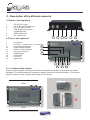
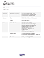
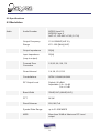
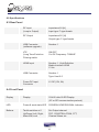
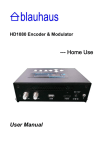
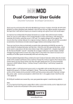
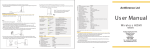
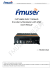
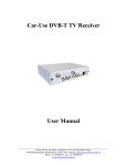
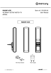
MINIMOD HD
Single DVB-T HDMI Modulator
USER MANUAL
Congratulations on your purchase of the Minimod HD Single DVB-T HDMI
Modulator
This ‘state of the art’ product, is an encoder. The video and audio inputs are taken from an
HDMI connection from the source device. The RF output is selectable and configured as a
DVB-T modulator.
Configuration is made through the integral control panel and OLED screen.
CONTENTS
1
Safety considerations
page 3
2
Description of the different elements
page 4
2.1
Back of unit explained
page 4
2.2
Top of unit explained
page 4
2.3 Location of the module
page 4
3
Operating instructions
page 5
3.1
Connecting to HDMI input
page 5
3.2
Connecting to RF input
page 5
4
Lock control
page 5
5
Menu controls
page 5
6
Parameters set up
page 5
6.1
Output channel setup
page 5
6.2
Setting up Constellation, FEC, guard interval, RF level
page 6
audio bit rate, audio format
6.3 Channel name edit
page 6
6.4
Setting up LCN, network name, audio pid, video pid
page 6
PMT pid, programme number, video bit rate
6.5 OLED Display
page 6
6.6
Factory reset
page 6
6.7
Saving configuration to USB
page 7
6.8
Firmware updates
page 7
7. Declaration of Conformity
page 7
8.
Specifications
page 8
8.1
Encoder specifications page 8
8.2
Modulation specifications
page 9
8.3
Rear panel specifications
page 10
8.4
Front panel specifications
page 10
8.5
Power and size specifications
page 11
2
1 SAFETY CONSIDERATIONS
1.1 Connecting to the mains supply
This product has to be connected to the mains supply. If there is the slightest doubt
concerning the type of connection available on the installation, please contact your supplier
of electricity. Before carrying out maintenance operation or modification of the installation,
the modulator has to be disconnected. Remark : only use the supplied power adaptor.
1.2 Over Voltage
An over voltage on the mains supply, can cause short circuits or fire. Never overload the
power lines.
1.3 Liquids
This module should be protected from splashes. Please assure yourself that no containers
containing liquids are placed on this module. Also be aware of other persons splashing
liquids on the module.
1.4 Cleaning
Disconnect the module before cleaning. Use only a damp cloth without solvents.
1.5 Ventilation
In order to assure an adequate air circulation and to prevent overheating, the ventilation
holes should not be obstructed. The module may not be installed in a hermetically sealed
environment. Other electronic products or heat producing items may not be placed upon or
near the module.
1.6 Accessories
The use of accessories not manufactured by the
manufacturer can cause damage to the module.
1.7 Installation of the module
The module must be installed in a place well protected from direct sunlight. All measures
have to be taken to avoid installation in humid or sunny places. Do not install near heating
elements or other devices producing heat. Assure yourself that the module is placed at least
15 cm from other equipment which is susceptible to electromagnetic radiation. Do not install
the module on unstable items, a fall can cause physical or material damage. Always ensure
the module is mounted vertically and not on its side.
3
2 - Description of the different elements
2.1 Back of unit explained
1
2
3
4
5
6
RF OUT: RF output
RF IN: RF input loop through
LTE: activates LTE filter
USB: USB connectivity for
upgrades/cloning
HDMI: HDMI input
DC: 12vDC input
1
2.2 Top of unit explained
7
8
9
10
11
12
13 14 15
16
2
3
4
5
6
Lock Button
Menu/OK: 1 x press menu, 2 x press OK
16
Left: backward selection
Right: forward selection
15
Down: List down selection
Up: List up selection
14
OLED Display
Power LED
Lock LED
Signal LED
7
9
8
2.3 - Location of the module
11
10
13
12
Leave a minimum space of at least 15cm above and below the product to guarantee an optimal
ventilation. The module should be mounted to assure a maximum natural ventilation. The module
should be fixed to a wall using the wall fixings on the module.
15cm
15cm
4
3. Operating Instructions
You can connect your distribution system using either the HDMI or RF inputs:
3.1 Connecting to HDMI input
You can connect your HDMI source device such as SKY receiver, BluRay player or Apple
TV into the HDMI input of the modulator.
3.2 Connecting to RF Input
You can connect FreeviewTM digital terrestrial services into the RF input. If no such services
are featured in the system, then it is recommended a 75[W] F-Type terminator is fitted
to this terminal. You can use a coax cable to connect the RF output to your distribution
system.
The
4. Lock control
This is a double use button.
You can use the (Lock) control button on the front panel to prevent
accidental tampering after installation. A single press will either lock or
unlock the installation controls. The LED will illuminate to indicate that the
panel is locked.
button is also used for space/delete during the menu edit function channel name.
5. Menu/OK
To access the list of functions to programme the modulator, press the
menu button once. To save the settings, press twice to confirm.
6. Parameters Setup
The following parameters can be programmed:
6.1 Output Channel Setup
Press ‘Menu/OK’ button and the OLED screen will display: ‘freq/ch_**’.
Press the qor p buttons to select the desired output channel. If you do
not want to setup other parameters, press ‘Menu/OK’ button and on the
display appears ‘save config? yes ( * ) no ( )’. Press ‘Menu/OK’ again to
save the setting. To set up other parameters, press t or u to make your
selection. When all your selections are complete, press ‘Menu/OK’ twice to
save the settings.
5
set up..
6.2 Setup Constellation, FEC, FFT, Guard Interval, RF Level, Audio Bit
Rate, Audio Format
Press ‘Menu/OK’ button and then use the t or u buttons to select the
desired function.
Use qor p buttons to select the correct value. When your selections are
complete, press ‘Menu/OK’ twice to save the setting
6.3 Channel ‘NAME’ edit
Press ‘Menu/OK’ button and then use the t or u buttons to select the
‘name’ function. Press the p button to reveal the first flickering character.
Then use the t or u buttons to change the character. To stop editing,
press the p button or press the q button to edit another character. Use
the button to delete the flickering character. The button also functions as
a 'space' button. To end the editing process, press ‘Menu/OK’ button twice and save the
‘name’ field that you edited. To select other parameters, press the p button to end the
‘name’ editing function and use the t or u buttons to choose another programming
option.
6.4 LCN Setup, Network Name, Audio pid, Video pid, PMT pid,
Programme Number, Video Bit Rate.
Press ‘Menu/OK’ button and then use the t or u buttons to select the
desired function such as ‘‘lcn’’. Press the p button to reveal the first
flickering number. Then use the t or u buttons to change the number,
press the q button to select another number. To stop editing, press the p
button. To proceed to another function, press the t or u buttons. When your selections
are complete, press ‘Menu/OK’ twice to save the setting.
LED off?
Factory
reset?
6.5 Turn off OLED Display.
Press ‘Menu/OK’ button and then use the t or u buttons to select the
‘led off?’ function. Press the p button to turn off the OLED display. Press
‘Menu/OK’ button again to activate the OLED display.
6.6 Factory Reset.
Press ‘Menu/OK’ button and then use the t or u buttons to select the
‘factory reset’ function to resume to default settings. Press the p button
to start reset to default factory values . The display will appear ‘success!’
when the procedure is completed.
6
6.7 Saving configuration to USB.
After adjusting the settings to the desired specifications, these settings can
then be copied onto a USB drive and stored for future use. The information
can also be used for programming another MINIMOD HD device where
multiple units need to be programmed with the same specifications. To save
this information, press ‘Menu/OK’ button and then use the t or u buttons
to select the ‘save to usb’ option. Press the p button to start to start saving process and
then the display will appear ‘success!’ when the procedure is completed.
6.8 Firmware Updates.
This device is capable of being updated with periodic firmware releases.
These can be downloaded from www.antiference.co.uk and installed into
the modulator using the following procedure:
1. Download the appropriate firmware release from the Antiference
website.
2. Copy the ‘jedi.img’ file to a USB memory stick.
3. Turn the Minimod HD off.
4. Insert the USB memory into the USB port at the rear of the Modulator
5. Turn the Minimod HD on.
6. When the OLED display appears ‘upgrade yes ( * ) no ( )’ press the
‘Menu/OK’ button
The upgrade procedure will finish after approximately 10 seconds.
Upgrade
yes(x) no( )
CAUTION
DO NOT turn the Minimod HD OFF while undergoing the firmware update procedure as this
may seriously damage the device.
7. DECLARATION OF CONFORMITY
We, Antiference LIMITED herewith declare that the modulator Minimod HD complies with all
essential requirements and any other applicable conditions set forth on directive 1999/05/
CE.
According to the WEEE (Waste Electrical and Electronic Equipment) EU Directive, do
not dispose of this product as household waste or commercial waste. Waste electrical
and electronic equipment should be appropriately collected and recycled as required by
practices established for your country. For information on recycling of this product, please
contact your local authorities, your household waste disposal service or the shop where you
purchased the product.
Date of issue: October 2014
7
8.0 Specifications
8.1 Encoder
Processor Processor Frequency
Host CPU: 200MHz 32Bit RISC
Security Processor: 200MHz 32Bit
Audio Processor: 200MHz 32Bit
Memory
Ram
DDRII 16Bit 512Mbit x 1 Embedded
Flash
NOR Flash 32Bit x 1
Video
Video Encoder
ISO/IEC 11172-2 MPEG
ISO/IEC 13818-2 MPEG2 MP@HL
ISO/IEC 14496 MPEG4 compliant
Support SP@L3 to ASP@L5
ISO/IEC 14496-10 AVC,
HP@level 4.1, MP@level 4.1
H.264 profile 0
JPEG base-line, progressive
Aspect Ratio
16:9 wide screen, 4:3 letter box,
4:3 pan scan, support AFD(DTG, MingDTG)
1080i,up to 1080p@30FPS
Resolution
8
8.0 Specifications
8.2 Modulation
Audio Audio Encoder
MPEGI layer1/2,
MPEGII Layer II
AAC LC, HE-AAC v1/V2 (2- CH)
Output Frequency
Range
Output Impedance
174~233MHZ(VHF III),
470 - 858 [MHz](UHF)
50[W]
Input Impedance
(loop to output)
50[W]
Forward Error
Correction
Guard Interval
1/2,2/3,3/4, 5/6, 7/8
QPSK,16QAM,64QAM
Constellations
1/4,1/8,1/16,1/32
RF Output Level
Default: 90 dBμV
Αdjustable: 0 to -14 dB
0 to + 6 dB
Band Width
7MHZ(VHF),8MHZ(UHF)
FFT
2K,8K
Reed Soloman
Symbol Rate Range
202,188,T=8
up to 31.668 MBPS
MER
More than 35dB at Maximum RF Level output
9
8.0 Specifications
8.3 Rear Panel
RF Input
(Loop to Output)
Impedance:50 [W]
Input type: F-type female
RF Output
Impedance:50 [W]
Output type: F-type female
USB Connector (software upgrade)
Number: 1
LTE
(Long Term Evolution
Filtering switch
ON/OFF
Cut Off Frequency: 790MHZ
HDMI Input
Number: 1, High Definition
Media Interface HDMI
V1.4a
USB Connector
Number: 1
Type: Host 2.0
Power DC Input Connector
X1 DC(12V, 2A)
8.4 Front Panel
Display Display
128x32 dots OLED Display
(IIC or SPI communication protocol)
LED
Power & work state LED POWER/LOCKED/SIGNAL Indicator
Buttons
Tactile switches x 6
Up/Down/ Left, Right,
Menu/OK,Lock Set Output channel
FEC, CONSTELLATION, FFT,
Channel Name etc.
10
8.0 Specifications
8.5 Power and size
Power Power Supply Unit
Adapter Input: 100-240V
AC Output: DC 12V/2.0A
Power Consumption
<10W
Size
Overall Dimensions
(W)164mm x (D)104mm x (H) 41mm
Construction
Casework
Printed Circuit Board
Metal cabinet with ventilation holes
2 layer PCB structure
11
www.antiference.co.uk