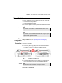
1
JDSU 6000/6000A Platform Scalable Test Platform designed for installation, commissioning, maintenance and troubleshooting of fiber networks User Manual JDSU 6000/6000A Platform Scalable Test Platform designed for installation, commissioning, maintenance and troubleshooting of fiber networks User Manual Notice Every effort was made to ensure that the information in this document was accurate at the time of printing. However, information is subject to change without notice, and JDSU reserves the right to provide an addendum to this document with information not available at the time that this document was created. Copyright © Copyright 2012 JDSU, LLC. All rights reserved. JDSU, Enabling Broadband and Optical Innovation, and its logo are trademarks of JDSU, LLC. All other trademarks and registered trademarks are the property of their respective owners. No part of this guide may be reproduced or transmitted electronically or otherwise without written permission of the publisher. Trademarks JDSU and MTS/T-BERD 6000B are trademarks or registered trademarks of JDSU in the United States and/or other countries. Microsoft, Windows, Windows CE, Windows NT, and Microsoft Internet Explorer are either trademarks or registered trademarks of Microsoft Corporation in the United States and/or other countries. Netscape Navigator is a trademark or registered trademark of Netscape Communications Corporation in the United States and other countries. Specifications, terms, and conditions are subject to change without notice. All trademarks and registered trademarks are the property of their respective companies. Ordering This guide is a product of JDSU's Technical Information Development information Department, issued as part of the User Manual. The ordering number for a published guide is E6000BM02. WEEE Directive JDSU has established processes in compliance with the Waste Electrical Compliance and Electronic Equipment (WEEE) Directive, 2002/96/EC. This product should not be disposed of as unsorted municipal waste and should be collected separately and disposed of according to your national regulations. In the European Union, all equipment purchased from JDSU after 2005-08-13 can be returned for disposal at the end of its useful life. JDSU will ensure that all waste equipment returned is reused, recycled, or disposed of in an environmentally friendly manner, and in compliance with all applicable national and international waste legislation. User Manual 760000002/10 v It is the responsibility of the equipment owner to return the equipment to JDSU for appropriate disposal. If the equipment was imported by a reseller whose name or logo is marked on the equipment, then the owner should return the equipment directly to the reseller. Instructions for returning waste equipment to JDSU can be found in the Environmental section of JDSU’s web site at www.jdsu.com. If you have questions concerning disposal of your equipment, contact JDSU’s WEEE Program Management team at [email protected]. vi User Manual 760000002/10 Table of Contents About This Guide xvii Purpose and scope . . . . . . . . . . . . . . . . . . . . . . . . . . . . . xviii Assumptions. . . . . . . . . . . . . . . . . . . . . . . . . . . . . . . . . . xviii Technical assistance . . . . . . . . . . . . . . . . . . . . . . . . . . . xviii Conventions . . . . . . . . . . . . . . . . . . . . . . . . . . . . . . . . . . . xix Chapter 1 6000/6000A Platform Overview 1 About the 6000/6000A Platform . . . . . . . . . . . . . . . . . . . . . .2 Main features . . . . . . . . . . . . . . . . . . . . . . . . . . . . . . . . . . . .2 Hard keys and indicators . . . . . . . . . . . . . . . . . . . . . . . . . . .5 Front panel hard keys . . . . . . . . . . . . . . . . . . . . . . . . . . . .5 Front panel indicators . . . . . . . . . . . . . . . . . . . . . . . . . . . . .6 Chapter 2 Safety information 9 Battery and AC/DC safety information . . . . . . . . . . . . . . . .10 Precautions relating to optical connections . . . . . . . . . . . 11 Laser Safety instructions . . . . . . . . . . . . . . . . . . . . . . . . . . 11 Laser classes . . . . . . . . . . . . . . . . . . . . . . . . . . . . . . . . . 11 Warning labels for the laser classes . . . . . . . . . . . . . . . . . . 11 User Manual 760000002/10 vii Table of Contents Chapter 3 Starting up 13 Unpacking the instrument . . . . . . . . . . . . . . . . . . . . . . . . .14 Installing and removing a plug-in unit in the 6000/6000A Platform . . . . . . . . . . . . . . . . . . . . . . . . . . . . . . . . . . . . . . .14 Inserting a plug-in unit into the 6000/6000A Platform . . . . . .14 Removing a plug-in . . . . . . . . . . . . . . . . . . . . . . . . . . . . .15 Choosing the position of the instrument on the work surface . . . . . . . . . . . . . . . . . . . . . . . . . . . . . . . . . . . . . . . .15 Fitting the carrying handle . . . . . . . . . . . . . . . . . . . . . . . .15 Charging the battery . . . . . . . . . . . . . . . . . . . . . . . . . . . . . .16 Connecting the mains adapter. . . . . . . . . . . . . . . . . . . . . .16 Charging the battery . . . . . . . . . . . . . . . . . . . . . . . . . . . .16 Battery charge level display . . . . . . . . . . . . . . . . . . . . . . .16 Switching the 6000 / 6000A Platform on and off . . . . . . . .17 Switching on the 6000 / 6000A Platform . . . . . . . . . . . . . . .17 Switching off the 6000 / 6000A Platform . . . . . . . . . . . . . . .17 Resetting the 6000 / 6000A Platform . . . . . . . . . . . . . . . . .18 Chapter 4 Configuring the 6000/6000A Platform 19 Displaying the System Settings screen . . . . . . . . . . . . . . .20 Defining the regional settings of the system . . . . . . . . . . .21 Defining the screen parameters of the 6000/6000A Platform . 22 Backlight. . . . . . . . . . . . . . . . . . . . . . . . . . . . . . . . . . . . .22 Contrast . . . . . . . . . . . . . . . . . . . . . . . . . . . . . . . . . . . . .22 Screen Saver . . . . . . . . . . . . . . . . . . . . . . . . . . . . . . . . .23 Defining the Automatic shutdown of the 6000/6000A Platform . . . . . . . . . . . . . . . . . . . . . . . . . . . . . . . . . . . . . . .23 Chapter 5 LTS (Loss Test Set) 25 The principle of optical power and attenuation measurements . . . . . . . . . . . . . . . . . . . . . . . . . . . . . . . . . .26 Power measurements . . . . . . . . . . . . . . . . . . . . . . . . . . .26 Attenuation measurements (optical link loss) . . . . . . . . . . .26 Connection to the power meter and the source. . . . . . . . .27 Configuring the LTS . . . . . . . . . . . . . . . . . . . . . . . . . . . . . .28 viii User Manual 760000002/10 Table of Contents Configuring the measurement parameters of the power meter . 28 Configuring the alarm parameters of the power meter . . . . .29 Configuring and displaying the parameters of the source . . .30 Display of results and commands . . . . . . . . . . . . . . . . . . .31 Result of the measurement in progress . . . . . . . . . . . . . . .31 Table of results . . . . . . . . . . . . . . . . . . . . . . . . . . . . . . . .31 Commands of the power meter parameters . . . . . . . . . . . .32 Making a measurement . . . . . . . . . . . . . . . . . . . . . . . . . . .33 Power measurement . . . . . . . . . . . . . . . . . . . . . . . . . . . .33 Optical link loss . . . . . . . . . . . . . . . . . . . . . . . . . . . . . . . .33 Setting the zero value of the power meter . . . . . . . . . . . .33 Carrying out the reference measurement . . . . . . . . . . . .34 Measurements on the fiber under test . . . . . . . . . . . . . .34 Performing an ORL Manual measurement with the 6000 / 6000A Base Unit . . . . . . . . . . . . . . . . . . . . . . . . . . . . . . . . .34 Establishing a reference for an ORL manual measurement .34 ORL Emitted power. . . . . . . . . . . . . . . . . . . . . . . . . . .35 ORL Zero adjustment . . . . . . . . . . . . . . . . . . . . . . . . .36 Measurement acquisition . . . . . . . . . . . . . . . . . . . . . . . . .37 Storing and reloading LTS/ORL results . . . . . . . . . . . . . . .38 File Setup . . . . . . . . . . . . . . . . . . . . . . . . . . . . . . . . . . . .38 Storing results . . . . . . . . . . . . . . . . . . . . . . . . . . . . . . . . .38 Loading results . . . . . . . . . . . . . . . . . . . . . . . . . . . . . . . .38 Chapter 6 VFL (Visual Fault Locator), Talkset and Data Transfer 41 Connection to the VFL and Talkset . . . . . . . . . . . . . . . . . .42 VFL Function . . . . . . . . . . . . . . . . . . . . . . . . . . . . . . . . . . .42 Talkset / Datalink Function . . . . . . . . . . . . . . . . . . . . . . . . .43 Talkset configuration . . . . . Connections . . . . . . . . . . . Establishing communication Adjusting volume level . . . . Disconnection . . . . . . . . . . . . . . . . . . . . . . . . . . . . . . . . .43 . . . . . . . . . . . . . . . . . . . . . . .43 . . . . . . . . . . . . . . . . . . . . . . .44 . . . . . . . . . . . . . . . . . . . . . . .44 . . . . . . . . . . . . . . . . . . . . . . .45 Remote screen function via Talkset . . . . . . . . . . . . . . . . . .45 Chapter 7 Scope 47 Scope feature . . . . . . . . . . . . . . . . . . . . . . . . . . . . . . . . . . .48 User Manual 760000002/10 ix Table of Contents Overview . . . . . . . . . . . . . . . . . . . . . . . . . . . . . . . . . . . .48 Installation of tips . . . . . . . . . . . . . . . . . . . . . . . . . . . . . . . .48 Configuring the P5000i Scope . . . . . . . . . . . . . . . . . . . . . .49 Scope connection . . . . . . . . . . . . . . . . . . . . . . . . . . . . . .49 Configuring the Scope . . . . . . . . . . . . . . . . . . . . . . . . . . .49 Test . . . . . . . . File parameters Fiber . . . . . . . Link Description . . . . . . . . . . . . . . . . . . . . . . . . . . . . .49 . . . . . . . . . . . . . . . . . . . . . . . . . . . . .50 . . . . . . . . . . . . . . . . . . . . . . . . . . . . .51 . . . . . . . . . . . . . . . . . . . . . . . . . . . . .51 Adding a new profile . . . . . . . . . . . . . . . . . . . . . . . . . . . .52 About page . . . . . . . . . . . . . . . . . . . . . . . . . . . . . . . . . . .52 Starting up with the scope . . . . . . . . . . . . . . . . . . . . . . . . .53 Freeze mode . . . . . . . . . . . . . . . . . . . . . . . . . . . . . . . . . .53 High Mag. / Low Mag. . . . . . . . . . . . . . . . . . . . . . . . . . . .54 Camera mode . . . . . . . . . . . . . . . . . . . . . . . . . . . . . . . . .54 Launching a test of the connector and fiber end-face . . . .54 Launching a test of the connector and fiber end-face . . . . . .54 Overlay. . . . . . . . . . . . . . . . . . . . . . . . . . . . . . . . . . . . . .55 Mosaic Mode . . . . . . . . . . . . . . . . . . . . . . . . . . . . . . . . .56 Loading a picture . . . . . . . . . . . . . . . . . . . . . . . . . . . . . . .57 File menu . . . . . . . . . . . . . . . . . . . . . . . . . . . . . . . . . . . . . .58 Saving the test result in a jpg file . . . . . . . . . . . . . . . . . . . .58 Generating a report . . . . . . . . . . . . . . . . . . . . . . . . . . . . .58 Chapter 8 Applications 61 PDF viewer . . . . . . . . . . . . . . . . . . . . . . . . . . . . . . . . . . . . .62 Opening a PDF document . . . . . . . . . . . . . . . . . . . . . . . .62 Interacting with a PDF document . . . . . . . . . . . . . . . . . . . .62 Web browser . . . . . . . . . . . . . . . . . . . . . . . . . . . . . . . . . . . .63 Configuring the Web access . . . . Starting the web browser . . . . . . Opening an internet page . . . . . . Navigation into the Web Browser . Using the bookmarks . . . . . . . . . . . . . . . . . . . . . . . . . . . .63 . . . . . . . . . . . . . . . . . . .63 . . . . . . . . . . . . . . . . . . .63 . . . . . . . . . . . . . . . . . . .64 . . . . . . . . . . . . . . . . . . .65 Creating bookmarks . . . . . . . . . . . . . . . . . . . . . . . . . .65 Opening a PDF document . . . . . . . . . . . . . . . . . . . . . . . .65 Leaving the web browser . . . . . . . . . . . . . . . . . . . . . . . . .66 Calculator . . . . . . . . . . . . . . . . . . . . . . . . . . . . . . . . . . . . . .66 File Explorer . . . . . . . . . . . . . . . . . . . . . . . . . . . . . . . . . . . .67 x User Manual 760000002/10 Table of Contents Chapter 9 Transferring the 6000/6000A Platform Interface 69 Establishing connection . . . . . . . . . . . . . . . . . . . . . . . . . . .70 Connecting the 6000/6000A Platform and the PC . . . . . . . .70 Configuring the 6000/6000A Platform. . . . . . . . . . . . . . . . .70 Transferring the Interface . . . . . . . . . . . . . . . . . . . . . . . . . .73 Virtual control buttons bar . . . . . . . . . . . . . . . . . . . . . . . . .74 Equivalence between the keyboard and 6000/6000A Platform . . . . . . . . . . . . . . . . . . . . . . . . . . . . . . . . . . . . . . .74 Chapter 10 File management 77 File Explorer Overview . . . . . . . . . . . . . . . . . . . . . . . . . . . .78 Directories and Files selections . . . . . . . . . . . . . . . . . . . . .78 Directory selection . . . . . . . . . . . . . . . . . . . . . . . . . . . . . .78 Files selection . . . . . . . . . . . . . . . . . . . . . . . . . . . . . . . . .79 Directories & Files editing functions . . . . . . . . . . . . . . . . .79 Copy/Cut & Paste files/directories . . . . . . . . . . . . . . . . . . .79 Renaming a directory / file . . . . . . . . . . . . . . . . . . . . . . . .80 Deleting a directory / file . . . . . . . . . . . . . . . . . . . . . . . . . .80 Working with directories and files from the explorer. . . . .80 Creating a directory . . . . . . . . . . . . . . . . . . . . . . . . . . . . .80 Opening files . . . . . . . . . . . . . . . . . . . . . . . . . . . . . . . . . .81 File Types . . . . . . . . . . . . . . . . . . . . . . . . . . . . . . . . .81 Sorting files . . . . . . . . . . . . . . . . . . . . . . . . . . . . . . . . . . .82 Transferring files to/from a PC with a FTP server . . . . . . . .83 Direct connection . . . . . . . . . . . . . . . . . . . . . . . . . . . .83 Connection via a local network . . . . . . . . . . . . . . . . . . .84 Accessing the internal memory of the 6000/6000A Platform 84 Sending files by mail . . . . . . . . . . . . . . . . . . . . . . . . . . . .86 Configuring the sending of files by e-mail . . . . . . . . . . . .86 Sending files from the Explorer . . . . . . . . . . . . . . . . . . .86 Creating a screenshot . . . . . . . . . . . . . . . . . . . . . . . . . . . .87 Configuring the parameters of screenshots . . . . . . . . . . . . .87 Taking a screenshot . . . . . . . . . . . . . . . . . . . . . . . . . . . . .88 Name of the screenshots files . . . . . . . . . . . . . . . . . . . . . .88 Creating a report . . . . . . . . . . . . . . . . . . . . . . . . . . . . . . . . .89 Configuring the report . . . . . . . . . . . . . . . . . . . . . . . . . . .89 Creating the report . . . . . . . . . . . . . . . . . . . . . . . . . . . . . .89 Name of the report . . . . . . . . . . . . . . . . . . . . . . . . . . . . . .90 User Manual 760000002/10 xi Table of Contents Merging pdf or txt files . . . . . . . . . . . . . . . . . . . . . . . . . . . .91 Storage media . . . . . . . . . . . . . . . . . . . . . . . . . . . . . . . . . . .92 Storage media built into the 6000/6000A Platform . . . . . . . .92 External USB storage media . . . . . . . . . . . . . . . . . . . . . . .92 USB memory stick connection . . . . . . . . . . . . . . . . . . .92 USB memory stick disconnection . . . . . . . . . . . . . . . . .92 Abbreviations for storage media . . . . . . . . . . . . . . . . . . . .93 Chapter 11 Smart Access Anywhere 95 Connection modes . . . . . . . . . . . . . . . . . . . . . . . . . . . . . . .96 Ethernet or WIFI connection . . . . . . . . . . . . . . . . . . . . . . .96 USB/WIFI connection through 3G Smartphone . . . . . . . . . .97 Pre-requisite for using the Smart Access Anywhere Application . . . . . . . . . . . . . . . . . . . . . . . . . . . . . . . . . . . . .98 Downloading the JDSU application on PC . . . . . . . . . . . . .98 Launching the SmartAccess Anywhere application . . . . .99 On 6000/6000A Platform . . . . . . . . . . . . . . . . . . . . . . . . .99 On the distant PC . . . . . . . . . . . . . . . . . . . . . . . . . . . . .100 Using Remote screen and File Transfer applications . . .101 Transferring the interface onto the PC . . . . . . . . . . . . . . .101 Transferring files . . . . . . . . . . . . . . . . . . . . . . . . . . . . . .103 Transferring files from PC to 6000/6000A Platform . . . . .104 Transferring files from 6000/6000A Platform to PC . . . . .104 Working with files and directories on 6000/6000A Platform .105 Connection information and settings. . . . . . . . . . . . . . . .105 Displaying session information . . . . . . . . . . . . . . . . . . . .105 Modifying connection settings . . . . . . . . . . . . . . . . . . . . .106 Testing connection . . . . . . . . . . . . . . . . . . . . . . . . . . . . .107 Chapter 12 WIFI Option 109 Installation of the WIFI option in the Platform . . . . . . . . . 110 Configuring the WIFI access . . . . . . . . . . . . . . . . . . . . . . 110 Connection to SSID . . . . . . . . . . . . . . . . . . . . . . . . . . . . . 111 Configuring the WIFI mode to which the Platform is connected . . . . . . . . . . . . . . . . . . . . . . . . . . . . . . . . . . . . . 112 Transferring the 6000/6000A Platform interface via WIFI on a PC . . . . . . . . . . . . . . . . . . . . . . . . . . . . . . . . . . . . . . . . . . . 114 xii User Manual 760000002/10 Table of Contents Transferring files to/from a PC via WIFI . . . . . . . . . . . . . . 115 Chapter 13 Bluetooth option 117 Setting up a Bluetooth connection. . . . . . . . . . . . . . . . . . 118 Transferring files via Bluetooth . . . . . . . . . . . . . . . . . . . .121 Transferring the Platform interface on a laptop PC via Bluetooth . . . . . . . . . . . . . . . . . . . . . . . . . . . . . . . . . . . . .122 Removing the Pairing . . . . . . . . . . . . . . . . . . . . . . . . . . . .124 Chapter 14 Technical specifications 125 Display . . . . . . . . . . . . . . . . . . . . . . . . . . . . . . . . . . . . . . .126 Screen . . . . . . . . . . . . . . . . . . . . . . . . . . . . . . . . . . . . .126 Memory . . . . . . . . . . . . . . . . . . . . . . . . . . . . . . . . . . . . . . .126 Input/Output . . . . . . . . . . . . . . . . . . . . . . . . . . . . . . . . . . .126 Power supply . . . . . . . . . . . . . . . . . . . . . . . . . . . . . . . . . .126 Battery . . . . . . . . . . . . . . . . . . . . . . . . . . . . . . . . . . . . .126 Mains adapters . . . . . . . . . . . . . . . . . . . . . . . . . . . . . . .127 Dimensions - Weight . . . . . . . . . . . . . . . . . . . . . . . . . . . .127 Environment . . . . . . . . . . . . . . . . . . . . . . . . . . . . . . . . . . .128 Temperature Humidity . . . EMI/ESD . . Drop test. . . Shocks . . . . Bumps . . . . Vibration . . . Flammability . . . . . . . . . . . . . . . . . . . . . . . . . . . . . . . . .128 . . . . . . . . . . . . . . . . . . . . . . . . . . . . . . . . .128 . . . . . . . . . . . . . . . . . . . . . . . . . . . . . . . . .128 . . . . . . . . . . . . . . . . . . . . . . . . . . . . . . . . .128 . . . . . . . . . . . . . . . . . . . . . . . . . . . . . . . . .128 . . . . . . . . . . . . . . . . . . . . . . . . . . . . . . . . .129 . . . . . . . . . . . . . . . . . . . . . . . . . . . . . . . . .129 . . . . . . . . . . . . . . . . . . . . . . . . . . . . . . . . .129 Characteristics of the options . . . . . . . . . . . . . . . . . . . . .129 Power meter of the LTS option . . Talkset . . . . . . . . . . . . . . . . . . . Laser sources of the LTS option . Manual ORL . . . . . . . . . . . . . . . VFL . . . . . . . . . . . . . . . . . . . . . Bluetooth and WIFI . . . . . . . . . . User Manual 760000002/10 . . . . . . . . . . . . . . . . . .129 . . . . . . . . . . . . . . . . . .129 . . . . . . . . . . . . . . . . . .130 . . . . . . . . . . . . . . . . . .130 . . . . . . . . . . . . . . . . . .130 . . . . . . . . . . . . . . . . . .131 xiii Table of Contents Chapter 15 Options and accessories 133 References of options for the 6000/6000A Platform mainframe . . . . . . . . . . . . . . . . . . . . . . . . . . . . . . . . . . . . .134 References of scopes and associated accessories . . . . .136 References of accessories . . . . . . . . . . . . . . . . . . . . . . . .136 Chapter 16 Maintenance and Troubleshooting 139 Maintenance procedure . . . . . . . . . . . . . . . . . . . . . . . . . .140 Cleaning . . . . . . . . . . . . . . . . . . . . . . . . . . . . . . . . . . . .140 Cleaning plates and housings . . . . . . . . . . . . . . . . . . .140 Cleaning the screen . . . . . . . . . . . . . . . . . . . . . . . . .140 Cleaning the optical cable connector . . . . . . . . . . . . . .141 Cleaning the optical connections of the 6000/6000A Platform . 141 Accessing to the 6000/6000A Platform information . . . . . .141 General page . . . . . . . . . . . . . . . . . . . . . . . . . . . . . .141 Software options page . . . . . . . . . . . . . . . . . . . . . . . .142 Services Data page. . . . . . . . . . . . . . . . . . . . . . . . . .142 Accessing to the 6000/6000A Platform documentation . . . .142 Installing a new version of the software . . . . . . . . . . . . . .143 Downloading from Internet . . . . . . . . . . Installation from JDSU Server . . . . . . . . Installation from another server . . . . . . . Installation from a USB memory stick . . . Launching the upgrade . . . . . . . . . . . . Checking new upgrade on JDSU Server . Upgrading from the boot . . . . . . . . . . . . . . . . . . . . . .143 . . . . . . . . . . .144 . . . . . . . . . . .146 . . . . . . . . . . .146 . . . . . . . . . . .147 . . . . . . . . . . .148 . . . . . . . . . . .149 Install Option . . . . . . . . . . . . . . . . . . . . . . . . . . . . . . . . .149 Enter Manually the Licence . . . . . . . . . . . . . . . . . . . .150 Import the license from the USB memory stick . . . . . . . .151 Locking the 6000/6000A Platform . . . . . . . . . . . . . . . . . .152 Returning an instrument . . . . . . . . . . . . . . . . . . . . . . . . .153 Guarantee conditions . . . . . . . . . . . . . . . . . . . . . . . . . . .153 Recycling Information . . . . . . . . . . . . . . . . . . . . . . . . . . .154 Troubleshooting . . . . . . . . . . . . . . . . . . . . . . . . . . . . . . . .154 Interpreting alarms . . . . . . . . . . . . . . . . . . . . . . . . . . . . .154 Formatting the USB memory stick onto the 6000/6000A Platform 155 Erase disk/harddisk . . . . . . . . . . . . . . . . . . . . . . . . . . . .155 xiv User Manual 760000002/10 Table of Contents Touchscreen calibration . . . . . . . . . . . . . . . . . . . . . . . . .156 Changing the battery . . . . . . . . . . . . . . . . . . . . . . . . . . .156 Removing the damaged battery. . . . . . . . . . . . . . . . . .156 Setting a new battery . . . . . . . . . . . . . . . . . . . . . . . .157 General information on warranty . . . . . . . . . . . . . . . . . . .158 Hardware Warranty . . . . . . . . . . . . . . . . . . . . . . . . . . . .158 Warranty disclaimer . . . . . . . . . . . . . . . . . . . . . . . . . . . .159 Appendix A Calibration Recommended 161 Recommended Calibration Period . . . . . . . . . . . . . . . . . .162 Appendix B USB printers supported by the 6000/6000A Base Unit 163 Selecting a printer connected to the 6000 6000/6000A Platform . . . . . . . . . . . . . . . . . . . . . . . . . . . . . . . . . . . . . .164 List of printers’ manufacturers and models available with the 6000/6000A Platform . . . . . . . . . . . . . . . . . . . . . . . . . .165 Index 179 User Manual 760000002/10 xv Table of Contents xvi User Manual 760000002/10 About This Guide The 6000/6000A Platform of JDSU provides a handhled modular platform designed for the construction, turn-up and maintenance of fiber networks. The topics discussed in this chapter are as follows: – “Purpose and scope” on page xviii – “Assumptions” on page xviii – “Technical assistance” on page xviii – “Conventions” on page xix User Manual 760000002/10 xvii About This Guide Purpose and scope Purpose and scope The purpose of this guide is to help you successfully use the 6000/6000A Platform features and capabilities. This guide includes task-based instructions that describe how to install, configure, use, and troubleshoot the 6000/6000A Platform. Additionally, this guide provides a complete description of JDSU’s warranty, services, and repair information, including terms and conditions of the licensing agreement. Assumptions This guide is intended for novice, intermediate, and experienced users who want to use the 6000/6000A Platform effectively and efficiently. We are assuming that you have basic computer and mouse/track ball experience and are familiar with basic telecommunication concepts and terminology. Technical assistance If you need assistance or have questions related to the use of this product, call or e-mail JDSU’s Technical Assistance Center for customer support. Table 1 Technical assistance centers Region Phone Number Americas Telecom Products 866 228 3762 World Wide: 301 353 1550 [email protected] Europe, Africa, and Mid-East +49 (0) 7121 86 1345 (Europe) [email protected] +33 (0) 1 30 81 50 60 (JDSU France) [email protected] Asia and the Pacific Southeast Asia, Australia, and New Zealand +852 2892 0990 (Hong Kong) All others 866 228 3762 xviii +86 10 6833 7477 (Beijing-China) User Manual 760000002/10 [email protected] About This Guide Conventions During off-hours, you can request assistance by doing one of the following: – leave a voice mail message at the Technical Assistance number in your region – e-mail North American Technical Assistance Center, [email protected], or European Technical Assistance Center, [email protected] – submit your question using our online Technical Assistance Request form at www.jdsu.com. Conventions This guide uses naming conventions and symbols, as described in the following tables. Table 2 Typographical conventions Description Example User interface actions appear in this typeface. On the Status bar, click Start. Buttons or switches that you press on a unit appear in this TYPEFACE. Press the ON switch. Code and output messages appear in this typeface. All results okay Text you must type exactly as shown appears in this typeface. Type: a:\set.exe in the dialog box Variables appear in this typeface. Type the new hostname Book references appear in this typeface. Refer to Newton’s Telecom Dictionary A vertical bar | means “or”: only one option can appear in a single command. platform [a|b|e] Square brackets [ ] indicate an optional argument. login [platform name] Slanted brackets < > group required arguments. <password> User Manual 760000002/10 xix About This Guide Conventions Table 3 Keyboard and menu conventions Description Example A plus sign + indicates simultaneous keystrokes. Press Ctrl+s A comma indicates consecutive key strokes. Press Alt+f,s A slanted bracket indicates choosing a submenu from menu. On the menu bar, click Start > Program Files. Table 4 Symbol conventions This symbol represents a general hazard. This symbol represents a risk of electrical shock. NOTE This symbol represents a Note indicating related information or tip. This symbol, located on the equipment or its packaging indicates that the equipment must not be disposed of in a landfill site or as municipal waste, and should be disposed of according to your national regulations. Table 5 Safety definitions WARNING Indicates a potentially hazardous situation which, if not avoided, could result in death or serious injury. CAUTION Indicates a potentially hazardous situation which, if not avoided, may result in minor or moderate injury. xx User Manual 760000002/10 Chapter 1 6000/6000A Platform Overview 1 This chapter provides a general description of the 6000/6000A Platform. Topics discussed in this chapter include the following: – “About the 6000/6000A Platform” on page 2 – “Main features” on page 2 – “Hard keys and indicators” on page 5 User Manual 760000002/10 1 Chapter 1 6000/6000A Platform Overview About the 6000/6000A Platform About the 6000/6000A Platform The functions and options available for the MTS/T-BERD 6000 and for the MTS/T-BERD 6000A are quite different. The MTS/T-BERD 6000 is a physical layer test platform. It manages exclusively the fiber optic modules (OTDR LR, SRL, VSRE; PMD, CD...) which do not require high power management. The MTS/T-BERD 6000A is a multiple layer test platform. It allows to manage Fiber Optics Modules, but also Multiple Services Application Modules (SDH/SONET, Ethernet and Triple Play). For this reasons, both products are differently equipped: the MTS/TBERD 6000A is equipped with high power battery pack, a touchscreen and a memory extension on standard, whereas those elements are optional with the MTS/T-BERD 6000. Moreover, the MTS/T-BERD 6000A is equipped with additional fans compared to the MTS/T-BERD 6000. MTS/T-BERD 6000 MTS/T-BERD 6000A Fiber Optics Module MSAM Module High Power Battery Pack Touchscreen Memory Extension Optional Fig. 1 + Fiber Optics Module Standard Differences between 6000 & 6000A Platforms Main features The 6000/6000A Platform is equipped with the following elements: – 2 8.4 inch TFT color screen, high visibility (optimized for outdoor use), which can be touchscreen (on option with the 6000 Base Unit, and on standard with the 6000A Base Unit) User Manual 760000002/10 Chapter 1 6000/6000A Platform Overview Main features – RJ45 plug for Ethernet interface – Two USB 2.0 host connectors for Microscope, USB memory stick, mouse, keyboard... – An audio jack to connect a headset – A connection socket for the mains adapter providing the 19 V power supply and used to charge the battery. – LED indicators for Charge, On status and Testing – One Li-Ion battery (option) – One high power Li-Ion battery (option, for the 6000A Platform) – a module, interchangeable in the field: OTDR, OLP, OSA... – Built-in Power Meter, VFL and/or Talkset (options) – A hard disk (option) With the 6000/6000A Platform, the user can: – Open and/or transfer files to a PC via a USB memory stick, Bluetooth (option) or WIFI (option) – Generate pdf reports – Open all user documentations included into the 6000/6000A Platform – Update the 6000/6000A Platform firmware – Remote the screen of the 6000/6000A Platform onto a PC and issue commands from the keyboard of the PC – ... Fig. 2 User Manual MTS/T-BERD 6000/6000A with module 760000002/10 3 Chapter 1 6000/6000A Platform Overview Main features Menu keys Hard keys Indicators 8.4’’ TFT Touchscreen Hard keys Indicators Direction keys Fig. 3 6000/6000A Platform - Front Panel description VFL Talkset Power Meter Headset jack Fig. 4 4 User Manual RJ45 USB Connection plug 6000/6000A Platform Connectors - Upper view 760000002/10 Chapter 1 6000/6000A Platform Overview Hard keys and indicators Hard keys and indicators Front panel hard keys Fig. 5 Table 6 Hardkeys Hard keys and Indicators Hard keys description Function Main on/off switch Gives access to: User Manual – selection of the different measurement or functions – the settings of the instrument – the help page 760000002/10 5 Chapter 1 6000/6000A Platform Overview Hard keys and indicators Table 6 Hard keys description Hardkeys Function This button calls up the file explorer. It allows to: – choose the storage medium: internal memory, USB memory key... – manage files; with facilities for classifying them in directories and sub-directories. This button calls up the measurement configuration menu. This menu depends on the function in use. This button calls up the results page (e.g. with OTDR module: reflectometry trace and table of results). This button is used to enter a sequence of commands and execute it Starts and stops the measurement. NOTE All these functions, except SYSTEM, depend on the modules used and the measurements made: refer to the user manuals of the corresponding modules of the 6000/6000A Platform. The direction keys have two principal functions: Front panel indicators – on the Results page, they are used to move the cursors or modify the zoom factor. – on the set-up pages, they are used to scroll through the menus, the central button serving to select or confirm the parameter chosen. The 6000/6000A Platform is equipped with three indicators, lit into a different color according to the status of the equipment. Table 7 Indicators Status On indicator Solid green 6 User Manual The instrument is operating, either on battery or on an external power supply. 760000002/10 Chapter 1 6000/6000A Platform Overview Hard keys and indicators Table 7 Indicators Status The instrument is switched off but connected Blinking green to an external power source. Charge indicator Solid green The instrument is connected to an external power source and the battery charge is in progress. Testing indicator Solid red User Manual At least one function is in measurement phase (for example, the laser emission pilot for an OTDR measurement) 760000002/10 7 Chapter 1 6000/6000A Platform Overview Hard keys and indicators 8 User Manual 760000002/10 Chapter 2 Safety information 2 This chapter gives the main information on the safety conditions when using the 6000/6000A Platform: – “Battery and AC/DC safety information” on page 10 – “Precautions relating to optical connections” on page 11 – “Laser Safety instructions” on page 11 User Manual 760000002/10 9 Chapter 2 Safety information Battery and AC/DC safety information Battery and AC/DC safety information – The Li-Ion battery is designed for maximum safety. In particular, each cell is provided with a safety valve to prevent excessive internal pressure in the event of overcharging or exposure to very high temperatures. – Battery supplied by JDSU incorporate protection means. Do not use any mains adaptor or battery other than those supplied with the instrument, or supplied by JDSU as an option for this instrument. If another adapter or battery is used, it may damage the 6000/6000A Platform itself. Using the 6000/6000A Platform with a battery other than the one supplied by the manufacturer of the 6000/6000A Platform may entail risks of fire or explosion. The battery may explode, leak or catch fire: – – if it is exposed to high temperature or fire if it is opened or dismantled. Example of reference for the battery supplied with the equipment: – MTS/T-BERD 6000: Li204SX – MTS/T-BERD 6000A: Ni2040HD Reference for the adapter for both Platforms: EA1050B-190 (60W max) Other basic safety precautions are as follows: 10 – Do not use AC/Adapter/Charger outdoors or in wet or damp locations – Connect the AC/Adapter/Charger to the correct mains voltage, as indicated on the ratings label. – Do not allow anything to rest on the power cord, and do not locate the product where people can walk on the power cord. – Avoid using this product during an electrical storm. There may be a remote risk of electric chock from lightning. – Do not use this product in the vicinity of a gas leak or in any explosive environment. – Do not attempt to service this product yourself, as opening or removing covers may expose you to dangerous, high voltage points and other hazards. Contact qualified service personal for all service. User Manual 760000002/10 Chapter 2 Safety information Precautions relating to optical connections Precautions relating to optical connections – The normal operating life of an optical connector is usually of the order of a few hundred manipulations. It is then advisable to manipulate the optical connections of the Platform as rarely as possible. – The proper operation of the instrument and its accuracy of measurement are dependent on the cleanliness of the environment and the optical connectors as well as the care taken in its manipulation. – The optical connectors must therefore be clean and dust-free. If the optical connection is not being used, protect the connections of 6000/6000A Platform using the protective caps. Laser Safety instructions The provisions contained in two standards define the safety procedures to be observed both by users and by manufacturers when utilizing laser products: – EN 60825-1: 2001 - Safety of laser products – Part 1: Classification of products, requirements and user guidelines. – FDA 21 CFR § 1040.10 - Performance standards for light-emitting products - Laser products. Due to the range of possible wavelengths, power values and injection characteristics of a laser beam, the risks inherent in its usage vary. The laser classes form groups representing different safety thresholds. Laser classes Warning labels for the laser classes Standards EN 60825-1, Edition 1.2, 2001-08 and FDA21CFR§1040.10: – Talkset option: Class 1M. – VFL option: Class 2. Due to the reduced dimensions of the optical modules, it is not possible to attach the required warning labels to them. In line with the provisions of Article 5.1 of the EN 60825-1 standard, the laser class identification labels are shown below: Ref. standard EN 60825-1, Edition 1.2, 2001-08 FDA21CFR§1040.10 Class 1 User Manual CLASS 1 LASER PRODUCT 760000002/10 11 Chapter 2 Safety information Laser Safety instructions Ref. standard EN 60825-1, Edition 1.2, 2001-08 FDA21CFR§1040.10 Class 2 LASER RADIATION DO NOT STARE INTO BEAM CLASS 2 LASER PRODUCT CAUTION LASER RADIATION - DO NOT STARE INTO BEAM CLASS II LASER PRODUCT The user must take the necessary precautions concerning the optical output of the instrument and follow the manufacturer’s instructions. Measurements on optical fibers are difficult to execute and the precision of the results obtained depends largely on the precautions taken by the user. 12 User Manual 760000002/10 Chapter 3 Starting up 3 This chapter describes the first steps to perform when using the 6000/ 6000A Platform. The topics discussed in this chapter are as follows: – “Unpacking the instrument” on page 14 – “Installing and removing a plug-in unit in the 6000/6000A Platform” on page 14 – “Charging the battery” on page 16 – “Switching the 6000 / 6000A Platform on and off” on page 17 User Manual 760000002/10 13 Chapter 3 Starting up Unpacking the instrument Unpacking the instrument 1 Remove the 6000/6000A Platform and its accessories from the packing case. 2 Check that the module and accessories ordered are all there. If any part is missing or damaged please contact your local JDSU agent. The 6000/6000A Platform is delivered with the following accessories: – a user manual – a mains adapter used for mains operation of the instrument and battery charging. – a soft carrying case (option) NOTE If the 6000/6000A Platform is delivered with an OSA-110M module, a specific hard case is delivered: E60HCASE-OSA. Installing and removing a plug-in unit in the 6000/6000A Platform The 6000/6000A Platform must be switched off and, if it is operating on the mains, its supply cable must be unplugged. Inserting a plug-in unit into the 6000/6000A Platform 1 Slide the plug-in into its slot. 2 When the plug-in is fully home, press firmly on the screen-printed face of the plug-in while tightening the clamping screws. The screen-printed face of the plug-in must be flush with that of the 6000/6000A Platform. Make sure that the two large captive screws of the plug-in are screwed fully home. Captive screws fixing the plug-in Fig. 6 14 User Manual Module installed into the 6000/6000A Platform 760000002/10 Chapter 3 Starting up Choosing the position of the instrument on the work surface Removing a plug-in 1 Unscrew the two captive fixing screws of the plug-in completely (up to the stop). 2 Carefully slide the plug-in out of its slot. Choosing the position of the instrument on the work surface Depending on the conditions of use of the 6000/6000A Platform, the instrument may be placed on a flat surface or held in the hand. When used on a work surface, the 6000/6000A Platform should be supported on its stay, which can be set in either of two positions, depending on whether the user is standing or sitting. To change the stay from “seated user” position to “standing user” position, press both sides to slide the stay towards the upper end of its groove, as shown in the drawings below. Fig. 7 Fitting the carrying handle Stay in positions for seated user and standing user A handle can be fixed to the 6000/6000A Platform in order to transport the equipment easier. To fit the handle: 1 Tighten the handle screw to the attachment point provided for that purpose, on the left and right sides of the equipment. Handle Fig. 8 Handle screw Fixing the handle To detach the handle from the instrument, unscrew the handle screws. User Manual 760000002/10 15 Chapter 3 Starting up Charging the battery Charging the battery Connecting the mains adapter 1 At the top of the 6000/6000A Platform (upper left-hand corner), lift up the power supply socket protector and plug in the mains adapter. 2 Connect the adapter to the mains. The On/Off indicator starts to blink in green. Use only the mains adapter supplied with the 6000 / 6000A Platform. The adapter for some other electronic device may appear to be identical, but entails a risk of damage to the 6000 / 6000A Platform. Charging the battery On connection to the mains: – if the user does not press ON, the battery will start the charge. – when the user presses the ON key, the instrument starts up and the battery will charge during use. Once the battery is fully charged, the Charge indicator is lit in solid green on the front panel. When the Charge indicator on the front panel is blinking red, this mean the power supply is not compatible with the battery used. Charge is disabled. It is essential to wait until charging is complete to ensure maximum independent operating time, which may otherwise be considerably reduced. Battery charge level display When the battery is installed in the instrument, a battery icon is displayed in the top right-hand corner of the screen. Example Icon Battery charge level From 100% to 70% From 70% to 40% From 40% to 10% From 10% to 0% 16 User Manual 760000002/10 Chapter 3 Starting up Switching the 6000 / 6000A Platform on and off – When the level becomes too low, the instrument emits a beep to inform the user until it switches off automatically after saving the current configuration and measurement. – The icon is displayed on the upper banner to indicate the Platform is connected to mains and battery is fully charged (100%). – If the icon is displayed , this mean the Platform is connected to mains but battery charge is inferior to 100%. Switching the 6000 / 6000A Platform on and off Switching on the 6000 / 6000A Platform 1 Press the ON/OFF key. If the Platform is powered to mains, the battery will charge. The On indicator pass from blinking to solid green. The JDSU logo appears on the screen briefly, then an autotest is carried out. The equipment is ready to be used once all the applications are installed. NOTE It is possible to switch over from battery to mains operation, or vice versa, without loss of data. The module cannot be swapped when the unit is ON or AC powered In the event of an unexpected mains power cut, if there is no battery, the current results and configuration will not be saved. Next time the instrument is switched on, it will return to its initial configuration. Switching off the 6000 / 6000A Platform While the 6000 / 6000A Platform is operating, press the ON/OFF button to switch it off. NOTE When the instrument is switched off using the ON/OFF button, current results and configuration are saved. Next time the ON/OFF key is pressed, they are recalled. User Manual 760000002/10 17 Chapter 3 Starting up Switching the 6000 / 6000A Platform on and off Resetting the 6000 / 6000A Platform 18 If the 6000 / 6000A Platform freezes, prolonged pressure (about 4 s.) on the ON/OFF key will reset the instrument User Manual 760000002/10 Chapter 4 Configuring the 6000/6000A Platform 4 This chapter describes the operations for configuring the instrument. The topics discussed in this chapter are as follows: – “Displaying the System Settings screen” on page 20 – “Defining the regional settings of the system” on page 21 – “Defining the screen parameters of the 6000/6000A Platform” on page 22 – “Defining the Automatic shutdown of the 6000/6000A Platform” on page 23 User Manual 760000002/10 19 Chapter 4 Configuring the 6000/6000A Platform Displaying the System Settings screen Displaying the System Settings screen To display the System Settings screen, you must: 1 Press the SYSTEM hard key to reach the Home page. Fig. 9 2 Home page Press the menu key System Settings Settings screen. see "Installing a new version of the soft- see “Transferring the 6000/6000A Platform see “Configuring the parameters of screenshots” page 87 and "Con- see “Sending files by mail” page 86 Fig. 10 20 to open the System User Manual System Settings page 760000002/10 Chapter 4 Configuring the 6000/6000A Platform Defining the regional settings of the system Defining the regional settings of the system When the 6000/6000A Platform is delivered, it is automatically configured with the System Settings set by default in factory, especially the language and date/time (Language: English / Date format: dd/mm/yyy / Time format: 24 hours clock). To modify the regional parameters in the System Settings page: 1 Click on Language and select the language to be used for the equipment. 2 Click on Date and enter the current date, using the numeric keypad displayed with the menu key Edit Number. 3 Click on Time and enter the current time, using the numeric keypad displayed with the menu key Edit Number. The date and time are displayed on the upper right side of the screen. or Select Net Time parameter and configure date and time according to a network (see “Net Time Synchronization” on page 21). 4 Click on Date Time Format and configure the following parameters: – – 5 Date format: select one of the option dd/mm/yy or mm/dd/yy. Time format: select one of the option 24 hour clock or 12 hour clock. Once all parameters have been defined, press Exit menu key to exit the System Settings page. Net Time Synchronization This parameter allows to configure the date and time of the Platform according to a network. – Dynamic Mode: the time is synchronized according to the local network. – Static Mode: in this case, the time is synchronized to the network server which is defined in the two following parameters. The two lines Server Name are displayed but cannot be modified. On the parameter Address Type, select if the address of the server which will be used for synchronisation is entered via its IP Address or via the Server Name. If IP Address is selected, enter one or two server addresses in the following parameters. During synchronization, the first address will always be used, but if a fail occurs, the second one will be used. User Manual 760000002/10 21 Chapter 4 Configuring the 6000/6000A Platform Defining the screen parameters of the 6000/6000A Platform If Server Name is selected, enter the name of the server, and if necessary a name for second server. During synchronization, the first server name will always be used, but if a fail occurs, the second one will be used. During synchronization, the icon displays for a few seconds. If Dynamic or Static mode is defined, the current Date and Time cannot be modified (parameters are greyed). If the network configuration is modified, synchronization may be lost. – None: the time is not synchronized according to a server. In this case, the user can reset date and time himslef, using the fields Date and Time. Defining the screen parameters of the 6000/6000A Platform In the System Settings page, the following parameters can be defined: Backlight 1 Click on Backlight 2 Define the backlight level of the screen, using the left and right direction keys, or clicking on Edit Number softkey and using the keypad displayed. – – Min backlight level: -5 Max backlight level: +5 If the 6000/6000A Platform is operating on battery, it is advisable to choose a minimum lighting level, acceptable for the user, to keep endurance as long as possible. Contrast 1 Click on Contrast 2 Select the type of environment into which the instrument is used: – – 22 Indoor: to be selected when the instrument is used inside (see Figure 10 on page 20) Outdoor: to be selected in order to optimize the readability of the screen for an outside use. User Manual 760000002/10 Chapter 4 Configuring the 6000/6000A Platform Defining the Automatic shutdown of the 6000/6000A Platform Fig. 11 Screen Saver Example of outdoor contrast Click on Screen Saver if you wish to activate a screen saver to the equipment, to extend the life of the battery, in case the 6000/6000A Platform is not used for some time. Instead of the normal screen, a small animated picture of the 6000/ 6000A Platform is displayed on the blackened screen. To configure the screen saver: 1 Click on Delay and select the time of inactivity before the screen saver starts: 60s, 3 min, 5 min. The parameter No deactivates the screen saver function. Defining the Automatic shutdown of the 6000/6000A Platform The automatic shutdown function switches off the 6000/6000A Platform automatically if no operation has been performed and no key actuated for a period selected from this menu. Work in progress is automatically saved. The function for automatically switching off the 6000/6000A Platform is available only on battery operation, to save the battery. 1 In the Utility box, click on Auto off parameter. User Manual 760000002/10 23 Chapter 4 Configuring the 6000/6000A Platform Defining the Automatic shutdown of the 6000/6000A Platform 2 Choose a time after which the 6000/6000A Platform will be switched off automatically, if no action has been done for that period: 5, 10 or 30 minutes. Select No if the 6000/6000A Platform must not be switched off, even if there is inactivity on the equipment. 24 User Manual 760000002/10 Chapter 5 LTS (Loss Test Set) 5 A variety of LTS options are available when ordering. Option 80/PM consists of a power meter only. The other options in the 80XXTS/PM series combine optical telephone, power meter and one or more sources of various wavelengths. See references in "References of options for the 6000/6000A Platform mainframe" page 134, for wavelengths of the sources in each option. The topics discussed in this chapter are as follows: – “The principle of optical power and attenuation measurements” on page 26 – “Connection to the power meter and the source” on page 27 – “Configuring the LTS” on page 28 – “Display of results and commands” on page 31 – “Making a measurement” on page 33 – "Performing an ORL Manual measurement with the 6000 / 6000A Base Unit" page 34 – “Storing and reloading LTS/ORL results” on page 38 User Manual 760000002/10 25 Chapter 5 LTS (Loss Test Set) The principle of optical power and attenuation measurements The principle of optical power and attenuation measurements Power measurements Attenuation measurements (optical link loss) A power meter, is all that is needed to measure emitted or received power: – to measure emitted power, connect the power meter directly to the output of the optical emitter; – to measure the power at the input of an optical receiver, the power meter is connected to the end of the fiber, at the point where the optical receiver would be connected. For measurement of the attenuation of power in a complete link or in elements such as sections of fiber, connections or optical components, a light source and a power meter are required. This attenuation is usually deduced from the measurement of optical power at two points: 2 1 Laser light source of the Reference Link under test Power meter of the 6000 / Attenuation A(dB) = P1 (dBm) - P2 (dBm) To perform accurate measurements, the following conditions are vital – Use one of the light sources of the LTS or a light source which is stable both in time and as a function of temperature. – Make sure that all connections and fibers and the receiving cell are perfectly clean. – Use a reference link between the laser source and the test subject. If several measurements are to be made under identical light injection conditions, this reference fiber must not be disconnected during the period while measurements are taking place. Insertion loss method 1 The power meter is first connected to the laser source via the reference fiber: P1 is measured. 2 Then the fiber to be tested is inserted between the reference fiber and the power meter: P2 is measured. The difference between P2 and P1 gives the attenuation of the fiber under test. 26 User Manual 760000002/10 Chapter 5 LTS (Loss Test Set) Connection to the power meter and the source It is preferable to use the same type of connector at both ends of the fiber being tested, to ensure the same connection conditions for measuring P1 and P2. Accuracy of measurements – A high degree of accuracy is often required. It is then necessary to perform a preliminary calibration without the fiber under test to eliminate the losses due to connections as far as this is possible. To do this, use the «Reference Value» function. – For measurements in the laboratory, where both ends of the fiber are on the same site, the repeatability of attenuation measurements is better than 0.1 dB. For measurements in the field, where the two ends are on different sites, variations from one measurement to another are of the order of ± 0.2 dB (using a relative measurement). Connection to the power meter and the source Power meter optical connection Optical connector of one of the sources Fig. 12 Optical connectors The type of optical connector used for the power meter is UPP (Universal Push Pull), which is compatible with all diameter 2.5 mm connectors (FC, SC, ST, DIN, E2000, etc.) If the source option is present, the source connection is the same as that for the talkset. User Manual 760000002/10 27 Chapter 5 LTS (Loss Test Set) Configuring the LTS Configuring the LTS The LTS function is an option chosen at the time of order and incorporated into the 6000 / 6000A Base Unit in the factory. To activate the function Power meter and / or Source: – Press the SYSTEM button – Use the direction keys to select the Power icon icon and press the confirmation key or Source : the icon in the frame will turn yellow. The effect of this action will to be to bring the power meter into use and / or to activate the source. Configuring the measurement parameters of the power meter The measurement parameters can be accessed with the SETUP key, once the icon is selected. Fig. 13 28 Configuration of power measurement Wavelength Selecting wavelength: - Auto: the wavelength of the input signal will be automatically detected and selected to perform the measurement: 850, 980, 1300, 1310, 1420, 1450, 1480, 1490, 1510, 1550, 1625 or 1650 nm: measurement performed at specified wavelength - User: choice of wavelength on the next line in the menu. User choice (if the User option was selected in the Wavelength line) selection of the wavelength between 800 nm and 1650 nm, in 1 nm steps, using the numeric keypad, displayed via the Edit Value key. User Manual 760000002/10 Chapter 5 LTS (Loss Test Set) Configuring the LTS Beep on modulation Select if a sound must be emitted on modulation or not (Yes / No) Unit Unit of power displayed: - Watt, dBm for displaying absolute power - dB for displaying a result relative to a reference (link loss) Reference level Select the reference value for the wavelength selected. First choose the wavelength, then press the > key to access choice of the value (+XXX.XX), then confirm this value with the validation key . This reference is also automatically available, in the Results page, using the Set as Reference key. Attenuator compensation Choice of level to be applied to the wavelength chosen for measurement to compensate for the loss due to the external attenuator (+XX.XX dB). First use the direction keys to choose the wavelength, then press > to access choice of value, then confirm this value by pressing the validation key . NOTE To copy a Reference Level or a Attenuator Compensator on all wavelengths, select the reference wavelength and click on Update for All Wavel.. Configuring the alarm parameters of the power meter Alarm Activation of the Alarm function: any result below the lower threshold or above the upper threshold will be displayed in red on the Results page. Lower and upper thresholds : Choice of lower and upper thresholds for each available wavelength, from -60 to +40 dBm. NOTE To copy one value of the Lower or/and Upper threshold for all wavelengths, select the reference value and click on Update for All Wavel.. User Manual 760000002/10 29 Chapter 5 LTS (Loss Test Set) Configuring the LTS NOTE A continuous push on the direction keys, increment the value of 10 dBm. Configuring and displaying the parameters of the source On the System page, select the Source icon and press RESULTS hardkey. The following page displays Fig. 14 Configuration of the source Laser Activation or shut-down of the laser (same function that the START/STOP button) When the laser is on, the icon is displayed. The parameters of the source can be accessed directly on the result screen of the LTS module, by clicking on Source Configuration soft key. Wavelength To change the wavelength when a multiwavelength source is present (depending on option). The wavelength value is displayed. Mode To vary the mode of emission of the source. Possible modulation values are: – 270 Hz – 330 Hz – 1 kHz – 2 kHz – Auto (the sources emit on determined frequencies to enable the power meter to detect the wavelength used automatically) – TwinTest (cyclical emission on all available wavelengths for a few seconds on each wavelength), compatible with the JDSU OLP 5/6/15/16/18. – CW (continuous emission) The mode used is displayed, above the icon Source Reference 30 User Manual . This key allows to display two other soft keys: 760000002/10 Chapter 5 LTS (Loss Test Set) Display of results and commands Standard Ref: this key allows to perform a reference measurement in standard mode, to measure the insertion loss. Jumper Ref: this key allows to perform a measurement in loopback mode using the power meter on Base-Unit and a Source on the OTDR Module onto this Base Unit (see user manual of the Module 8100 Series). NOTE The soft key Jumper Ref is not visible if both Power meter and Source are selected onto the Base-Unit. The power meter must be selected onto the Base-Unit, and the Source onto the OTDR Module to display/activate the soft key and to be able to perform a reference measurement in loopback mode. Display of results and commands The results page called up by the RESULTS button, gives the information relating to the measurement in progress, results previously saved and the commands available for measurement and saving. Result of the measurement in progress Table of results The power measured by the power meter is displayed in large characters, in the units selected in the SETUP menu, together with: – the mode of transmission of the signal measured: continuous (CW) or modulated to a frequency of 270Hz, 330Hz, 1KHz, or 2KHz. – the wavelength of the signal measured. – the reference level expressed in dB. – the level of Attenuation Compensation. For one and the same fiber, the power meter displays a table of 9 results corresponding to the different possible wavelengths. The table shows the power measured in dBm, the relative power (in dB) and the reference level in dBm (if units = dB), together with the mode. A measurement result is displayed in the table when the Keep Result softkey is pressed. The Clear Table softkey orders deletion of all the results displayed in the table. If the Alarm function has been activated, any result that exceeds the selected thresholds appears in red in the table. Otherwise, results are shown in the table in green. User Manual 760000002/10 31 Chapter 5 LTS (Loss Test Set) Display of results and commands When the instrument is switched off, results present in the table are not saved. Results of the power meter Fig. 15 Commands of the power meter parameters Results and commands of the LTS When the LTS function is selected, the following softkeys are available on the results page: Keep Result Saves the result on the corresponding line of the table. Clear Table Deletes all the results recorded in the table. Pressing the Power Config. key allows to reach the following function: Wavelength Allows to modify the wavelength to be applied with the Power meter. Unit Allows to modify the unit of power displayed (dB, dBm, nW) Zero Adjustment of the Zero value when the power meter’s optical input is closed with a plug (a validation is required). Click on Exit to go back to the Results page. Pressing the Pow. Reference key allows to reach the following function: Standard Reference Selects the current result as reference value to measure the attenuation of a link. This reference is displayed under the measurement result until a new reference value is chosen. 32 User Manual 760000002/10 Chapter 5 LTS (Loss Test Set) Making a measurement Jumper Reference This key can be pressed when a reference in loopback mode must be performed (see 8100 Module Series User Manual). The soft key Jumper Ref is not visible if both Power meter and Source are selected onto the Base-Unit. The power meter must be selected onto the Base-Unit, and the Source onto the OTDR Module to display/activate the soft key and to be able to perform a reference measurement in loopback mode. Making a measurement The power meter is started up as soon as the PowerMeter function is activated in the System page. Power measurement is automatically updated in consequence. The value «<-60 dB» is displayed when the laser is switched off and if the source output is looped on to the power meter input. If a 6000 / 6000A Base Unit source is used, the START/STOP key or the Laser on/Laser off soft key must be used to start or stop emission of light. Power measurement 1 Connect the light source to be tested to the rear connector (see "Connection to the power meter and the source" page 27). 2 In the SETUP menu, choose the units dBm, dB or Watts. 3 Press the START/STOP key to start the laser. The result will appear in the results page and can be memorized in the table (see "Table of results" page 31). 4 Press the START/STOP key to stop the laser. Optical link loss Setting the zero 1 Fix the plug over the optical input of the power meter so that no light can reach the photodiode of the power meter. If the zero adjustment value of the power is made without this plug, an error message may be displayed, as meter the photodiode will detect too much light. 2 In the Results page, press the Powermeter Config. > Zero soft keys and validate. User Manual 760000002/10 33 Chapter 5 LTS (Loss Test Set) Performing an ORL Manual measurement with the 6000 / 6000A Base Unit It is important to set the zero of the power meter before making any measurements where accuracy is required, as the noise from the germanium photodiode fluctuates over time and with variations in temperature. Carrying out the 1 Fix the adapter corresponding to the jumper to the optical connector of the power meter. reference measurement 2 Connect the jumper between the input of the power meter and the output of the source. 3 Configure the same wavelength on the source and the power meter. The power measured is displayed in the results page of the LTS. 4 Press the Power Reference > Standard Ref. soft key to save the result displayed as reference value. Measurements on After defining the reference value, proceed as follows to make the the fiber under test measurement: 1 Fix the jumpers and connectors needed to connect the fiber to be tested between the source output and the power meter input. 2 In the set-up menu, select dB units. 3 The power displayed in the Power Meter window corresponds to the optical loss of the link tested. It can be displayed in the table (see "Table of results" page 31). It is not possible to use the source at the same time than the Talkset option or the Data Transfer. Performing an ORL Manual measurement with the 6000 / 6000A Base Unit Using simultaneously the powermeter and talkset ports on the Base Unit allows to perform an ORL manual measurement. In the System page, select the icon ORL of the Base Unit. Establishing a reference for an ORL manual measurement Two steps must be carried out to take a reference for an ORL manual measurement: 34 User Manual 1 Power emitted reference 2 Zero ORL adjustment 760000002/10 Chapter 5 LTS (Loss Test Set) Performing an ORL Manual measurement with the 6000 / 6000A Base Unit Follow the order given above to take the reference. They are not two different processes but two steps necessary to establish a reference for an ORL measurement ORL Emitted 1 Once the ORL icon is selected, click on RESULT hardkey power The ORL page opens Fig. 16 2 ORL page Click on Zero key The message Put caps on the powermeter port then confirm displays: click on Yes to validate and wait for the second message, Dark current calibration completed then hit on any key to continue the process. 3 Click on ORL Power Emitted key 4 Follow the instruction on the upper part of the screen: connect the jumper from the talkset port to the powermeter one. 5 Click on Go 6 The message Measurement in progress... is displayed. 7 Once completed, the results for ORL Power Emitted are displayed for each wavelength. User Manual 760000002/10 35 Chapter 5 LTS (Loss Test Set) Performing an ORL Manual measurement with the 6000 / 6000A Base Unit Fig. 17 8 Power Emitted result Click on Exit to go back to the initial screen in order to perform the ORL Zero measurement Once the reference has been taken, the reference screen is updated for the wavelengths available. As the Zero measurement has not yet been done, the first line of the table displays the message Ref ORL: Incomplete. ORL Zero Once the Power Emitted measurement has been carried out, the Zero adjustment adjustment can be performed: ORL Zero cannot be performed on a bend insensitive fiber. 36 1 Click on ORL Zero 2 Follow the instructions displayed at the top of the screen: disconnect the jumper from the power meter port and wrap this jumper, still connected to the talkset port, around the mandrel (6 to 7 times). 3 Push the Go key 4 Once completed, the results displayed in the column Zero ORL. User Manual 760000002/10 Chapter 5 LTS (Loss Test Set) Performing an ORL Manual measurement with the 6000 / 6000A Base Unit Fig. 18 Results table with ORL Power emitted and Zero ORL for each wavelength Once the reference has been taken, the reference screen is updated for the wavelengths available. It indicates the type of reference used. Once the two references are complete, the date as well as the type and serial number of the local instrument are displayed on the first line of the table. If not, the message Ref ORL : Incomplete is displayed. Measurement acquisition Before making an ORL manual measurement, check that: – each end of the fiber is correctly connected to the module. – the fiber and jumpers are in good condition. To display the fiber measurement page, push the START/STOP key. User Manual 760000002/10 37 Chapter 5 LTS (Loss Test Set) Storing and reloading LTS/ORL results Fig. 19 – ORL Manual Measurement Click on Keep Results to keep the result displayed in the table. – Click on Clear Table to delete all the values kept. – Click on Wavelength key to change the Wavelength to be applied. Storing and reloading LTS/ORL results File Setup Storing results Click on the button FILE to access the File setup. See the chapter «File management» in the user manual «8100 modules series» for a complete description of all parameters, options and the explorer. In order to save the results of a LTS/ORL measurement, click on FILE and select Store trace. Two files are being saved : – The first file is to be used with the 6000 / 6000A Base Unit and allows to retrieve all LTS/ORL measurement results. It is saved with the extension «.Lts» / «.orl». – The second file is a ASCII file using tabulations to separate values. It is saved with the extension «.txt» and cannot be opened by the 6000 / 6000A Base Unit. It has been designed to be used with a spreadsheet program on a PC where it allows to retrieve all LTS/ ORL measurement results and format them in a nice customized table. Loading results In order to load the results of a LTS/ORL measurement: 38 User Manual 760000002/10 Chapter 5 LTS (Loss Test Set) Storing and reloading LTS/ORL results 1 Select a file with the extension «.Lts» in the file explorer (see the chapter «File management» in the user manual for «8100 modules series») 2 Select a file with the extension «.orl» in the file explorer (see the chapter «File management» in the user manual for «8100 modules series») 3 Click on Load then View trace(s). The LTS / ORL tab is displayed with the loaded results in the table. User Manual 760000002/10 39 Chapter 5 LTS (Loss Test Set) Storing and reloading LTS/ORL results 40 User Manual 760000002/10 Chapter 6 VFL (Visual Fault Locator), Talkset and Data Transfer 6 A variety of built-in optical options are available when ordering. See references in Chapter 15 “Options and accessories”, for details. The topics discussed in this chapter are as follows: – “Connection to the VFL and Talkset” on page 42 – “VFL Function” on page 42 – “Talkset / Datalink Function” on page 43 – “Remote screen function via Talkset” on page 45 User Manual 760000002/10 41 Chapter 6 VFL (Visual Fault Locator), Talkset and Data Transfer Connection to the VFL and Talkset Connection to the VFL and Talkset VFL Talkset optical VFL connection Fig. 20 VFL / Talkset connectors The type of optical connector used for the VFL source is UPP (Universal Push Pull), which is compatible with all diameter 2.5 mm connectors (FC, SC, ST, DIN, E2000, etc.). VFL Function This function is used to emit a red light signal of frequency 1 Hz or in continuous mode into a fiber to detect any defects in the dead zone of the reflectometer, or to identify it. This function is suitable for short fibers (length < 5 km) or the first few metres of a long fiber. NOTE Identification is facilitated by the blinking of light in the fiber. To emit a light signal into a fiber: 1 Connect the fiber to the VFL port on the connectors panel. 2 Press the SYSTEM key and activate the VFL The icons . display on the upper banner of the screen. The signal mode (1Hz or CW) of the VFL can be modified in the System Settings page, in Utility > VFL Mode parameter. The selection of this function is compatible with another function (ex OTDR...). 42 User Manual 760000002/10 Chapter 6 VFL (Visual Fault Locator), Talkset and Data Transfer Talkset / Datalink Function Talkset / Datalink Function The option enables two operators at opposite ends of an optical link: – To communicate along the fiber. – To transfer data along the fiber. Each end of the optical link must be provided with a 6000/6000A Platform equipped with the Talkset option. n NOTE It is possible to use the talkset of the 6000/6000A Platform and to carry out measurements at the same time, on a different fiber. NOTE It is possible to use the Data transfer feature while using the optical telephone of the 6000/6000A Platform. Nevertheless, the data transfer speed will be slightly decreased. Talkset configuration Connections The talkset configuration is set in the System Settings screen, in the Utility > Talkset menu (see "Adjusting volume level" page 44) At each end of the fiber: 1 Connect the fiber to the Talkset port of the 6000/6000A Platform, either directly or through jumpers. The Talkset connector is set with a FC adapter by default. Fig. 21 2 Installation for Talkset use A headset (with earphones and a microphone) supplied with the option may also be plugged into the 6000/6000A Audio jack. NOTE Data transfer uses the same fiber as the optical telephone User Manual 760000002/10 43 Chapter 6 VFL (Visual Fault Locator), Talkset and Data Transfer Talkset / Datalink Function Establishing communication On the caller 6000/6000A Platform, press the SYSTEM key, then validate the desired function: – Talkset the fiber. (Optical Telephone): used to communicate via – Datalink : used to transfer data along the fiber. If the remote instrument is ready to receive (on standby), the Talkset icon turns yellow, beeps are emitted, and – the icon appears at the top of the screen: telephone communication can now take place. – the icon take place. appears at the top of the screen: data transfer can now If the remote instrument is not ready to receive, the Talkset icon does not change color and a message is emitted. NOTE The talkset icon is displayed on the top banner as long as communication remains established, letting the user know that the connection is working. When communication is established, the headset is automatically enabled if plugged in. However, the loud speaker must be correctly configured in the setup menu to work accordingly NOTE Data transfer varies according to the type of application you use. For Fiber Optics for example, you can use the explorer. The distant 6000/ 6000A Platform will be shown just like a disk and all file and directory features can be used from and to that disk. Adjusting volume level 44 The sound is transmitted to the earphones of the headset and, if this function has been activated, to the speaker in the 6000/6000A Platform base. To activate the base loudspeaker and adjust the volume: 1 Press the SYSTEM key. 2 Press System Settings key to reach the System Settings page. 3 Under the Utility box, select Talkset. 4 Select the Conference mode: Speaker and micro off / Speaker only / Speaker and micro on 5 Under the Volume parameter, adjust the volume for speaker and micro (from 0 to 7). User Manual 760000002/10 Chapter 6 VFL (Visual Fault Locator), Talkset and Data Transfer Remote screen function via Talkset Disconnection When communication is over, deactivate the Talkset function on one of the 6000/6000A Platform. This deactivation can be done by either 6000/ 6000A Platform. Then, the fiber used for Talkset can be disconnected safely. Remote screen function via Talkset This enables an operator at one end of an optical link to take control over another 6000/6000A Platform connected at the other end, using the fiber. NOTE Each end of the optical link must be provided with a 6000/6000A Platform equipped with the Talkset option. VNC configuration Before it can be remote-controlled, the 6000/6000A Platform must be configured as explained in “Remote Screen” on page 70 . Connections At each end of the fiber (see Figure 21 on page 43): connect the fiber to the Talkset port of the 6000/6000A Platform, either directly or through jumpers. Remote screen via VNC is done via the data transfer feature, and on the same fiber as the optical telephone. Establishing communication On the caller 6000/6000A Platform, press the SYSTEM button, then select and confirm the Talkset option: 1 If the remote instrument is ready to receive (on standby), the Data icon turns orange, beeps are emitted, and the icon appears at the top of the screen: data transfer can now take place. If the remote instrument is not ready to receive, the Data icon does not change color and a message is emitted. 2 Click next on Expert tools, Remote Display, and on Switch to remote screen. Your screen is now fully replaced by the distant screen, and everything you do on your 6000/6000A Platform is in fact done on the distant 6000/6000A Platform. An icon form. User Manual appears in the top banner of the 6000/6000A Plat- 760000002/10 45 Chapter 6 VFL (Visual Fault Locator), Talkset and Data Transfer Remote screen function via Talkset A slight normal color degradation may be seen on the 6000/ 6000A Platform controlling a distant instrument. End of a VNC session In order to end a VNC session, you can: – Return to the menu Expert tools > Remote Display and click on Return to local screen. (Recommended solution) – Deactivate the data function on either 6000/6000A Platform connected. – Set Remote screen to off (see “Remote Screen” on page 70) – Disconnect the fiber NOTE The VNC icon in the top banner of the screen lets you know at all times whether you are in a VNC session or not. 46 User Manual 760000002/10 Chapter 7 Scope 7 The scope function is a hot-plug feature enabled directly when inserting a JDSU scope supplied as an accessory (see "References of accessories" page 136). The topics discussed in this chapter are as follows: – "Scope feature" page 48 – "Installation of tips" page 48 – "Configuring the P5000i Scope" page 49 – "Starting up with the scope" page 53 – "Launching a test of the connector and fiber end-face" page 54 – "File menu" page 58 User Manual 760000002/10 47 Chapter 7 Scope Scope feature Scope feature Overview This feature enables you to verify that your optical connectors are in perfect shape and very clean condition. The P5000i Digital Probe Microscope is a portable handheld microscope used to view and inspect both the bulkhead (female) and patch cord (male) sides of fiber connectors as well as other optical devices, such as transceivers. The P5000i requires an FBPT inspection tip and is connected to the 6000/6000A Platform with a USB 2.0 connector. QuickcaptureTM button Instantly captures (and analyzes) fiber image Focus Control Magnification Control Inspection tip Barrel assembly Fig. 22 6 FT COIL Cable USB 2.0 connector Latch lock Squeeze both ends to release P5000i Probe components Before using the P5000/P5000i scope, make sure the Bluetooth option has not been activated, even once, after the start of the MTS/ T-BERD 6000/6000A. If it has been activated, stop and restart the equipment before using the P5000/P5000i Scope. Installation of tips The Pass/Fail analysis function on the 6000/6000A Platform can only be used with certain inspection tips mounted on the P5000i. Seven tips, patchcords and bulkheads types, are delivered with the Videoscope Kit (EDFSCOPE5KI) but many others can be used. 48 User Manual 760000002/10 Chapter 7 Scope Configuring the P5000i Scope Configuring the P5000i Scope Scope connection 1 Plug in your JDSU scope into a USB port from the 6000/6000A Platform. 2 Push the button SYSTEM 3 Validate the Scope function 4 Connect probe with the fiber being inspected. . You may select this option while others are selected (e.g. OTDR). Configuring the Scope 1 Press SETUP key to configure the test. The following screen displays: Fig. 23 P5000i Scope Setup Test Profile On the line Profile, select the Profile which will be used for the test of fiber connector: – SM_UPC: Pass/Fail criteria for single-mode UPC connectors from IEC 61300-3-35 standard. – SM_APC: Pass/Fail criteria for single-mode APC connectors from IEC 61300-3-35 standard. – SM_PC: Pass/Fail criteria for single-mode PC connectors from IEC 61300-3-35 standard. – MM_: Pass/Fail criteria for multimode connectors from IEC 61300-335 standard. Profiles contain the analysis parameters by which Pass/Fail criteria are determined. User Manual 760000002/10 49 Chapter 7 Scope Configuring the P5000i Scope Once the line is selected, you can also add a new profile, clicking on the Add Button (see "Adding a new profile" page 52). Tip On the line Tip, select the tip set onto the scope to connect fiber for inspection. Capture button This parameter allows to select the action of the Quick Capture button onto the Scope (see Figure 22 on page 48): Freeze & Test pressing the button will automatically perform a test of fiber and freeze the result Freeze image pressing the button onto the Scope automatically freeze the live image. will Auto Center This parameter allows to select if the scope image must be centered on screen (select Yes) or not (select No). File parameters The File menu allows to enter a file name for saving scope test results. On the line Filenaming, use the edition keypad, which will display by clicking on the right arrow key, to enter a specific name for the file. You can enter manually a name and/or use pre-defined parameters (Fiber Id, Cable Id, Locations...). Predefined parameters for naming files Fig. 24 Edition keypad for naming scope file To add a logo to a report generated from test results, select Logo parameter and press right direction key to display the file explorer page and select the image which will be used as logo on the report page (see “Generating a report” on page 58). Click on menu key Load to validate the selection. The screen returns to configuration page and displays the file path in the Logo parameter. 50 User Manual 760000002/10 Chapter 7 Scope Configuring the P5000i Scope Fiber The Fiber box allows to configure the fiber plugged to the scope. On the line Fiber Id, enter a name for the fiber using the edition menu displayed via the right direction key. On the line Fiber Number, use the numeric keypad, which will display by clicking on the right arrow key, to enter the fiber number. On the line Change fiber Nbr, select if the fiber number must be modified after each results saving: No: the fiber number is not modified at each saving Increment; the fiber number is automatically incremented at each results saving Decrement: the fiber number is automatically decremented at each results saving. Link Description The information entered in the Link Description window concern the editing and/or the modifications of the cable and fiber parameters. – Cable Id: This parameter allows to enter an identification of the cable, using the Edition menu. – Direction: The direction shows if the acquisition has been made from the origin to the extremity (A->B) or from the extremity to the origin (B->A). Changing direction makes it possible, when different extremities are handled, to see the parameters of the fiber for the other extremity. – Location A: The name of the Location A of the link may be entered here. – Location B: The name of the Location B of the link may be entered here – Company: Allows to enter the name of the company carrying out the test. – Operator: Use the right arrow key to enter the name of the operator carrying out the test. NOTE All parameters of the Link Description box will appear in the pdf report generated from a test results page. Press Exit to return to the Results screen of the scope. User Manual 760000002/10 51 Chapter 7 Scope Configuring the P5000i Scope Adding a new profile Once the Setup screen of the scope is displayed, you can add a specific profile which will be used for the test. The profile must be created via FiberChek2TM, and stored on one storage media of the MTS/T-BERD 6000(A) (disk, or USB memory stick). 1 On the Setup screen, select Profile and press Add key. 2 On the explorer, select the file which will be used as profile (icon ; extension: .PRO) 3 Press Load. Once loaded, the display goes back automatically to Setup screen. 4 Select the profile just loaded. Removing a profile About page 1 In the Profile list, select the profile to be deleted. 2 Press Remove key., then Exit. On the Setup screen, the softkey About, on the right of the screen, allows to display information on scope and current test result displayed (in Full Screen mode or mosaic mode - see “Mosaic Mode” on page 56). 1 Press About softkey to display a page as the following one: Information on scope Information on active test result Fig. 25 52 User Manual About page 760000002/10 Chapter 7 Scope Starting up with the scope Starting up with the scope Once the FiberScope icon is validated: 1 Press RESULTS hard key Focus level for image sharpness Fig. 26 Example of the result using the P5000i scope Use the Focus Control button onto the P5000i scope (see Figure 22 on page 48) to adjust the image quality and sharpness. NOTE To switch from Scope page to FO results page and vice-versa, press the RESULTS hard key for about 2 seconds (a beep is emitted). Freeze mode Once the image is acceptable, you may freeze the picture. This feature allows to store in memory the resulting picture. Freezing a scope result does not store the picture in a file (see "File menu" page 58). The result will be lost if the instrument is shut off, or if more than 3 pictures are frozen (see "Mosaic Mode" page 56). NOTE The button set on the lead, or the QuickCapture™ on the P5000 allows to freeze the picture, and to launch a test (according to configuration in Setup page - see “Configuring the Scope” on page 49). User Manual 760000002/10 53 Chapter 7 Scope Launching a test of the connector and fiber end-face High Mag. / Low Mag. Camera mode The High Mag./Low Mag. menu key allows to switch the display from High to Low magnification and vice-versa. This function is also available pressing the button directly on the P5000i (see Figure 22 on page 48). If you are in Freeze mode, or in Mosaic mode, with a picture selected (see “Mosaic Mode” on page 56), press Camera menu key to return to live camera picture. Use the focus control to adjust the focus of the image Launching a test of the connector and fiber end-face Launching a test of the connector and fiber end-face Once the display is correctly adjusted (magnification, sharpness...), a test of fiber connector can be launched. To launch the test: 1 Press Test key to launch the test of plugged fiber connector. The test is completed: – – – once the Led Testing is no more lit in red once the icon is no more displayed on the upper banner once a screen as the following one displays: NOTE To configure the Pass/Fail critera, refer to “Configuring the Scope” on page 49. 54 User Manual 760000002/10 Chapter 7 Scope Launching a test of the connector and fiber end-face Summary of Test results Test result in High mag. Fig. 27 Test results A summary of test results is displayed on the right, upper part of the screen. – – Zone A: represents the Core zone: it is the area surrounding the core Zone B: represents the Cladding zone. It surrounds the majority of the fiber cladding. – Zone C: represents the Epoxy ring. – Zone D: represents the Ferrule/Contact zone: it identifies a portion of the ferrule near and around the fiber Zone D Zone C Zone B Zone A NOTE To return to a Live Camera image, press Live key; or press Full Scr./ Mosaic key to view both live image and test result. In Mosaic mode (see "Mosaic Mode" page 56), the result of the test only displays Pass or Fail information; the status of each zone is displayed only in full screen mode. Overlay The Overlay key allows, when selected, to display the limits of each zone and to display with colors the defaults on the image. When the key is unselected, the zones and defaults are not graphically identified. This function is also available in Mosaic Mode (see “Mosaic Mode” on page 56). User Manual 760000002/10 55 Chapter 7 Scope Launching a test of the connector and fiber end-face Mosaic Mode It is possible to display only one picture in full screen (640 * 390 pixels) or up to four pictures (320*180 pixels each, including the live camera picture) in mosaic mode. Use the key Full scr./Mosaic to switch from one mode to another. Position 2: Snapshot saved on disk : connector cleaned Selected picture Menu keys when Live picture is selected Position 1 : Live camera Position 3 : Connector before being cleaned Position 4 : JPEG image Fig. 28 – Mosaic mode You may select one of the pictures by clicking on it. The selected picture is framed in green. The toolbar on the right varies according to which picture is selected (camera, or static scope picture): Picture selected: Live Test Allows to launch a (new) test of the connector (see “Launching a test of the connector and fiber end-face” on page 54) Freeze Allows to freeze the live image and to save it later on the disk. Once this key is pressed, the freeze image is automatically set on Position 2. Overlay Allows to display/hide the limits of each zone and the detected defaults on image from a scope test result (see “Overlay” on page 55). If all positions were taken, the picture that was once at the fourth position is unloaded from memory. Frozen pictures are lost, unless they were saved on the internal memory. 56 User Manual 760000002/10 Chapter 7 Scope Launching a test of the connector and fiber end-face High mag./Low mag. Allows to switch all the images from high to low magnification and vice-versa. This key is not available with jpg files other than those resulting from scope application. Picture selected: Image Save Allows to save the selected picture in the directory Scope, in the disk of the Platofrm. Press Save key, enter a name for the jpg file and validate. This key is not available with jpg files other than those resulting from scope application. Comment Allows to add a comment to the selected picture (see “High Mag. / Low Mag.” on page 54) Overlay Allows to display or hide the limits of each zone and the defaults on image from a test result (see “Overlay” on page 55). This key does not work on jpg image which do not result from scope application. High mag./Low mag. Allows to switch all the images from high to low magnification and vice-versa. This key is not available with jpg files other than those resulting from scope application. Adding a comment A key Comment allows you to enter/modify a comment to your picture if necessary. This comment appears at the bottom left of the picture. The right bottom of the frozen picture also contains the date of the acquisition (where the picture was frozen). NOTE Both the comment and the date will be saved with the picture. Loading a picture It is possible to retrieve and load a picture stored in the Scope directory and display it in the Scope page. 1 Press the FILE button. 2 Select Load. 3 Select the JPEG file to be loaded via the Explorer User Manual 760000002/10 57 Chapter 7 Scope File menu 4 Click on Load >Confirm Load Recognized pictures are images resulting from the Scope option and saved on disk via the 6000/6000A Platform. Some pictures resulting from the Scope option may appear nevertheless unrecognized, if they have been stored with a different Scope application, or if the JPG file has been opened and modified under another JPG editor. Even though the JPG editor of the Scope function has been designed to display Scope pictures in black & white, it is also possible to open any JPG valid file and display in color the corresponding picture. That picture is enlarged or shrunk to the size of the display (full screen or mosaic, see."Mosaic Mode" page 56). File menu Saving the test result in a jpg file Once the test has been performed, and the result is displayed on the 6000/6000A Platform screen: 1 Press FILE key 2 Click on Save key to save a jpg file of the test result on the disk of the 6000/6000A Platform. 3 On the edition keypad, enter the name of the jpg file 4 Press Enter to validate. The file is automatically saved on the disk, in the directory Scope (icon ). Generating a report 1 Check the correct test result is selected (framed in green in mosaic mode). 2 Press the FILE button, then the Report key 3 On the edition keypad, enter the name of the pdf file and press ENTER. The report generation is completed once the icon displayed on the upper banner. is no more NOTE The pdf report will be saved on the disk, in the directory Scope. 58 User Manual 760000002/10 Chapter 7 Scope File menu Display of the report Once the report has been generated: 1 Press FILE hard key 2 On the right menu keys, press Load soft key. 3 In the File Explorer, select the pdf report just created. 4 Press Load > Confirm Load. Logo, company & parameters selected in the Setup page (see “Link Description” on page 51) Fig. 29 User Manual PDF report 760000002/10 59 Chapter 7 Scope File menu 60 User Manual 760000002/10 Chapter 8 Applications 8 Several desktop applications are provided to you, thanks to the integration of free software released under the free licences (GPL, LGPL, BSB or other). Their purpose is to bring more functionality to the 6000/6000A Platform. JDSU doesn’t provide any warranty or support regarding these free software. To access desktop applications, press the button SYSTEM, and the soft key App’s. The topics discussed in this chapter are as follows: – "PDF viewer" page 62 – "Web browser" page 63 – "Calculator" page 66 – "File Explorer" page 67 User Manual 760000002/10 61 Chapter 8 Applications PDF viewer PDF viewer Opening a PDF document The simplest way to open a pdf file is to press FILE. Select Explorer, look for your file and then select Load >Confirm Load to load the corresponding file. The file opens automatically in the PDF viewer. Another way used to open a pdf document is to press SYSTEM > App’s and select the PDF Reader icon. The PDF Reader opens but without document. To open a PDF document, click on the icon , or press FILE hard key, and select a document in the file explorer dialog box. Interacting with a PDF document Once your document is open, you may browse through different pages very quickly, zoom to a particular level, rotate the page... All these features are available via buttons on the screen. Rotate the page Go to 10 pages Go to previous page Go to next page Go to 10 pages more Exit PDF viewer Display the current page # Change zoom level Fig. 30 Open PDF Viewer Graphical User Interface NOTE You may scroll in all directions using the direction keys of the 6000/ 6000A Platform or of an external keyboard, or by dragging the scroll bars with touchscreen or mouse. 62 User Manual 760000002/10 Chapter 8 Applications Web browser Web browser Configuring the Web access Before using the Web Browser onto the 6000/6000A Platform, check/ modify the proxy configuration in the System Settings page: 1 Starting the web browser On the Home page, press System Settings menu key 2 Select Use proxy parameter in the I/O Interfaces box – If Manual is selected, enter the Proxy Address using the edition keypad – If Auto is selected, enter the Pac Address using the edition keypad. To access this application, on the Home page click on the soft key App’s. In the Application screen, activate Web Browser icon . The web browser is launched. Fig. 31 Opening an internet page Web Browser page Once the Web Browser is displayed, you must enter the internet address. 1 Set the cursor in the address bar: a Use the mouse connected via USB port on the 6000/6000A Platform or the mouse of the PC if the screen is deported via VNC application on the PC. b Click on the softkey Mouse User Manual 760000002/10 so that it becomes . 63 Chapter 8 Applications Web browser This allows to move the cursor toward the address bar, and to turn to cursor. 2 Once the cursor set onto the address bar, enter the address: a Using a keyboard connected to the 6000/6000A Platform USB port or the keyboard of the PC with a deport of the screen via VNC, enter the entire address of the site to be opened. b If none keyboard is available, click on Keyboard the virtual keyboard and enter the address: to display click directly on characters if the platform is equipped with a touchscreen. or Use the arrow keys (with Mouse key keyboard and enter the text 3 ) to reach the Push Enter to validate. The page opens If an error message is displayed in place of the internet page, verify the address you typed, or check the Web configuration (see "Configuring the Web access" page 63). Fig. 32 Navigation into the Web Browser Internet page opened with the Web Browser Once the Web Browser is open, push the key right of the screen, the buttons used to navigate. Icon Definition Go to the previous or next page loaded 64 User Manual 760000002/10 to display on the Chapter 8 Applications Web browser Icon Definition Refresh the actual page Exit the Navigation menu Using the bookmarks Once a page is opened, you can apply it a bookmark, in order to get a shortcut toward this page. Creating Once the internet page for which a bookmark must be created is opened: bookmarks 1 Click on to open the dialog box for bookmarks creation. New toolbar is available on the right of the screen. 2 Click on the menu key Add displayed 3 Click on the menu key Edit to edit the bookmark, and modify if necessary the name of the bookmark. Click on Ok to confirm the modification or Cancel to cancel the modifications. Fig. 33 Opening a PDF document to add a bookmark for the page Bookmark edition – Click on to open the page of the bookmark selected in the list – Click on to delete the selected bookmark from the list – Click on to exit the bookmark menu and go back to the Web Browser page. PDF documents may be opened and read within the Web browser. 1 When you click on a link toward a PDF file, a dialog box during loading is displayed. 2 Once loading is completed, click on Ok to open the pdf file. User Manual 760000002/10 65 Chapter 8 Applications Calculator Fig. 34 Downloading a pdf file NOTE The web browser will open a PDF document, not a URL including a PDF file. The PDF is also automatically saved on the disk of the 6000/6000A Platform. Leaving the web browser Depending on how long you want to leave the web browser and on your connection mode, you may: – Leave the web browser running and switch to another task. To do this, click on the SYSTEM button. To go back, you must select again the Web Browser in the App’s menu: – – – The icon is valid The application will reopen much faster, and all your environment will be the same (last current page, possibilities to go back...) Quit the application using the Web browser application menu: click on the key . Calculator A calculator can be displayed and used onto the 6000/6000A Platform. 1 In the Home page, press the App’s key 2 In the Application screen, select the icon Calculator. The icon is framed in white 3 66 Press User Manual to validate the selection and open the Calculator 760000002/10 Chapter 8 Applications File Explorer Fig. 35 Press Calculator to exit the Calculator and go back to the Application page. Press SYSTEM button to go back to the Home page, and keep the Calculator application active. File Explorer This key allows to directly open the 6000/6000A Platform explorer, where all the files are stored (traces, pdf files ...). The explanation about the explorer are available in “File management” page 77. User Manual 760000002/10 67 Chapter 8 Applications File Explorer 68 User Manual 760000002/10 Chapter 9 Transferring the 6000/6000A Platform Interface 9 The 6000/6000A Platform can be used in combination with a PC in order to transfer the Platform Interface onto a PC, or to access the internal memory or USB memory stick contents on the PC. Topics described in this chapter are as follows: – “Establishing connection” on page 70 – “Transferring the Interface” on page 73 – “Virtual control buttons bar” on page 74 – “Equivalence between the keyboard and 6000/6000A Platform” on page 74 User Manual 760000002/10 69 Chapter 9 Transferring the 6000/6000A Platform Interface Establishing connection Establishing connection The connection between 6000/6000A Platform and the PC can be done directly, or via a local network. The transfer of the interface can be done using a VNC window on PC. For an intensive use of the deport screen or when it is used via a WAN network, it is strongly recommended to use a dedicated VNC client. The VNC clients recommended are Tight VNC (V 1.2.9 or later) and Real VNC (V 4.1.1 or later). Connecting the 6000/6000A Platform and the PC 1 Connect the 6000/6000A Platform to the PC via an Ethernet cable, using the RJ45 connectors set on both equipments. Fig. 36 2 Connection 6000/6000A Platform and PC Check the network connection on the PC is set in Dynamic mode. NOTE The transfer of interface can be done via Wifi , using the IP address once WIFI connection is established (see Chapter 12 “WIFI Option” on page 109). It can also be transferred via Bluetooth, on a laptop PC equipped with Bluetooth (see Chapter 13 “Bluetooth option” on page 117). Configuring the 6000/6000A Platform 1 In the Home page, press System Settings menu key. 2 In the System Settings page, in the I/O Interfaces box, configure the following parameters: Remote Screen Remote screen = Session or Permanent must be confirmed in both cases, in the Interface E/S window. 70 User Manual 760000002/10 Chapter 9 Transferring the 6000/6000A Platform Interface Establishing connection No the screen cannot be remote on to a PC or on to another 6000/6000A Platform. Session Mode the Remote screen function is inactive once the 6000/6000A Platform is switched off. Permanent Mode the Remote screen function is still active when the 6000/6000A Platform is switched off and restarted. Permanent with password same function as the Permanent mode, with an access to the equipment via VNC protected by a password: 42000 The password to access VNC can be modified: 1 Click on the menu key Change password. 2 Enter the current password in the Edition keypad and press Enter to validate. 3 Enter the new password and press Enter to validate. Ethernet > Mode Parameters of the local Ethernet network to which the 6000/6000A Platform is connected: Config 1 to 4 – Site Name – IP Address – IP Mask – IP Gateway – DNS1 – Domain name Dynamic static mode enabling input of the configuration of 4 sites. If this parameter is selected, the following parameters must be entered: the user can enter the name of the site in the Edit menu. IP address of the 6000/6000A Platform address of the mask of the sub-network IP address of the machine enabling access outside the sub-network. IP address of the machine providing the IP address on the basis of the name name of the local network to which the 6000/ 6000A Platform is connected. in this mode, which requires a DHCP server, the 6000/6000A Platform requests an IP address from this server which will be allocated dynamically if dynamic host configuration is activated on the local network. After selecting this mode or after power-on, the 1.Domain Name Server User Manual 760000002/10 71 Chapter 9 Transferring the 6000/6000A Platform Interface Establishing connection 6000/6000A Platform tries to establish a connection to obtain an address from a DHCP server. If for any reason, this process fails, the 6000/6000A Platform reverses to static IP address mode with User1 IP address. NOTE Once the 6000/6000A Platform is connected to the network, the icon displays for few seconds and indicates the connection is working. Ethernet IPv6 > Mode The Ethernet IPV6 parameters must be configured to get Ethernet access in accordance with the IPV6 standards. Config 1 to 4 – Site Name – Link: – IP – GW – DNS Auto static mode enabling input of the configuration of 4 sites. If this parameter is selected, the following parameters must be entered: the user can enter the name of the site in the Edit menu. automatically displays the address of the link (cannot be modified) IP address of the 6000/6000A Platform IP address of the machine enabling access outside the sub-network. IP address of the machine providing the IP address on the basis of the name in this mode, the 6000/6000A Platform requests an IP address from the server which will be allocated automatically. If Auto is selected, the parameters Link, IP, GW and DNS are automatically defined and cannot be modified. Off The Ethernet IPV6 connection is not activated. Proxy > Use proxy 1 Select No if no proxy is used. 2 If Manual has been selected, enter the Proxy Address. Fig. 37 3 72 Example of proxy configuration If Auto has been selected, enter the Pac Address. User Manual 760000002/10 Chapter 9 Transferring the 6000/6000A Platform Interface Transferring the Interface 4 Note the IP Address displayed in the System Settings page. Note the 6000/6000A Platform IP Address Fig. 38 5 Example of configuration for Ethernet Wait about 10 seconds the connection is established. The 6000/6000A Platform Interface can now be transferred onto the PC, or the internal memory/USB key contents can be transferred on PC. Transferring the Interface Once the connection is established between the 6000/6000A Platform and the PC, proceed as follow: 1 Open Internet Explorer on the PC. 2 Considering 10.33.16.169 is the IP Address of the 6000/6000A Platform (as shown Figure 38 on page 73), enter the following address in the Internet Explorer window: http://10.33.16.169:5800 3 Press Enter to validate. The screen of the 6000/6000A Platform appears offset on your PC. Click to install TightVNC software on your PC (not mandatory) Fig. 39 User Manual VNC window 760000002/10 73 Chapter 9 Transferring the 6000/6000A Platform Interface Virtual control buttons bar You can use keyboard mouse of the PC to control the 6000/6000A Platform (see “Equivalence between the keyboard and 6000/6000A Platform” on page 74). NOTE Once Remote screen is accessbile via VNC, the icon displays on the upper banner of the screen until the connection is cut or the 6000/ 6000A Platform is switched off. When two or more users are using remote screen function onto the same Platform, the icon is . Virtual control buttons bar It is possible to emulate hard keys with Virtual Control buttons. This virtual control buttons bar is especially useful when the 6000/6000A Platform screen is exported on a remote PC. To display those buttons, click once on the top of the screen in the status bar, at the same height than the date and time. Fig. 40 Virtual control buttons bar The virtual control buttons bar is displayed during a few seconds. You may click on any of these buttons to obtain exactly the same results than using the hard keys on the front panel of the 6000/6000A Platform. Equivalence between the keyboard and 6000/6000A Platform The PC keyboard can replaced all the buttons and keys of the 6000/ 6000A Platform except the ON/OFF button: 74 – The menu keys to the right of the screen are replaced by the function keys F1 to F7. – The buttons below the screen are equivalent to Ctrl + a letter (see table below). – The direction keys have the same function on the external keyboard and on the 6000/6000A Platform. User Manual 760000002/10 Chapter 9 Transferring the 6000/6000A Platform Interface Equivalence between the keyboard and 6000/6000A Platform Function on the 6000/6000A Platform External keyboard HOME Ctrl + H SYSTEM SETTINGS F12 SET-UP Ctrl + U FILE Ctrl + F RESULTS Ctrl + R START/STOP Ctrl + S EXPORTa Ctrl + P Menu keys 1 to 7 (from top to bottom) F1 F7 ABOUT F11 Save and quit (Exit) Entrée/Enter Quit without saving (Abort) Escape/Echap. a. The Export function is available onto the Platform pressing simultaneously the left and right arrow keys. NOTE Those equivalences are also valid with a keyboard directly connected to the 6000/6000A Platform via one USB port. User Manual 760000002/10 75 Chapter 9 Transferring the 6000/6000A Platform Interface Equivalence between the keyboard and 6000/6000A Platform 76 User Manual 760000002/10 Chapter 10 File management 10 The files management with the 6000/6000A Platform can be performed, wether a module is set onto the equipment or not. The topics discussed in this chapter are as follows: – “File Explorer Overview” on page 78 – “Directories and Files selections” on page 78 – “Directories & Files editing functions” on page 79 – “Working with directories and files from the explorer” on page 80 – “Creating a screenshot” on page 87 – “Creating a report” on page 89 – “Merging pdf or txt files” on page 91 – “Storage media” on page 92 User Manual 760000002/10 77 Chapter 10 File management File Explorer Overview File Explorer Overview To reach the File Explorer page 1 2 On the Home page, press App’s softkey. Validate the File Explorer icon. The File Explorer page appears. Fig. 41 File Explorer page Directories and Files selections Directory selection To select a directory from the explorer page: 1 Press on the directory that must be selected on the left of the screen. The list of files the directory contains displays on the right side The selected directory is underlined in blue 2 Press validation hard key Access to sub-directory Fig. 42 78 User Manual Directory selection 760000002/10 , to display the sub-directories if any. Selected directory Sub-directory Chapter 10 File management Directories & Files editing functions Files selection To select one or several files from the explorer page: 1 Press on files that must be selected. or To select a list of files using the keys of the Platform: a Select and validate the first file of the list (underlined in red) b Set the cursor on the last file of the list (underlined in blue) c Maintain the right direction key selected. pushed until all the files are or Click on Select all menu key to select all files into the directory. NOTE The last selected file is underlined in red and the previous one(s) selected is/are underlined in blue. Selected directory Selected files Fig. 43 Example of files selection Directories & Files editing functions Copy/Cut & Paste files/ directories To copy (cut) one or several files, or one directory, and paste them in another place: 1 Select the directory / the file(s) (see “Directories and Files selections” on page 78). 2 Press Edit menu key User Manual 760000002/10 79 Chapter 10 File management Working with directories and files from the explorer 3 Press Copy to keep the directory / file(s) to their initial location. or Press Cut to delete the directory / file(s) from their initial location Renaming a directory / file 4 On the left of the screen, select the directory; or select the new storage media. 5 Click on Paste menu key. 1 Select the directory / file to be renamed (see “Directories and Files selections” on page 78). 2 Press Edit > Rename Directory or Rename File. The Edition keypad displays. Fig. 44 Deleting a directory / file Edition keypad for renaming file 3 Press Clear if you wish to delete the entire name 4 Enter a new name for the directory / file. 5 Click on Enter to validate the new name. 1 Select the directory or file(s) to be deleted (see “Directories and Files selections” on page 78). 2 Press Edit > Delete. A confirmation dialog box displays. 3 Press Yes to delete the selected directory or file(s). Press No to cancel the deletion. Working with directories and files from the explorer Creating a directory 80 To create a new directory from the explorer page: 1 Check the cursor is set on the left of the screen User Manual 760000002/10 Chapter 10 File management Working with directories and files from the explorer 2 Select the storage media into which the directory must be created 3 If you want to create a sub-directory, select the directory into which it must be created. 4 Press the right menu key Create Directory. The edition keypad displays Opening files 5 Enter a name for this directory 6 Press Enter key to validate the new directory Once a file is selected, press Load, then Confirm Load menu keys. Several FO files of the same type (example: all otdr) cannot be opened at the same time using the Explorer function of the Application page; only the last one selected will open. It can be opened exclusively if the corresponding module is set and activated and if File explorer is opened using the FILE button of the Platform). Other type of files (PDF, TXT...) must be open one by one. If different types of files have been selected in the Explorer, only the last one selected will open. File Types For files recognized by the 6000/6000A Platform, the types are symbolized by icons. E.g. Icon Type of FO file OTDR file (.SOR extension) Multi OTDR file (.MSOR extension) OEO file (.OEO extension) OSA file (.OSA extension) PMD file (.PMD extension) CD OTDR file (.CD extension) AP file (.AP extension ODM file (.OCD extension) ORL file (.ORL extension) User Manual 760000002/10 81 Chapter 10 File management Working with directories and files from the explorer Icon Type of FO file Power Meter file (.LTS extension) Icon Type of file PDF File (.PDF extension) PNG file (.PNG extension) XML file (.XML extension) JPEG / JPG file (.JPEG extension) HTML file (.HTML extension) Text file (.TXT extension) License file (.LIC extension) CSV file (.CSV extension) With the 6000/6000A Platform, you can open and load any kind of Fiber Optic files (OTDR, OSA, PON, LTS...) even if the corresponding module is not installed. Sorting files If at least one file is selected, the key Sort allows to access to a submenu allowing to sort the files according to pre-defined parameters: – Sort by name: the files display in an ascending order (from A to Z). If you click once again on the key, the files display in a descending order (from Z to A). – Sort by size: by clicking once on this key, the files display from the smallest to the heaviest one. Clicking a second time allows to sort the files in opposite order. – Sort by type: clicking once on this key; the 6000/6000A Platform displays files in an ascending order (the file type A to file type W). By clicking again, the 6000/6000A Platform displays the files in opposite order. – Sort by date: clicking once on this key; the 6000/6000A Platform displays files from the more recent to the less one. By clicking again on key, the Platform displays files from the older to the more recent one. NOTE You can also sort files clicking on the column titles in the files list 82 User Manual 760000002/10 Chapter 10 File management Working with directories and files from the explorer Transferring files to/from a PC with a FTP server Il is possible, from a PC, to access the internal memory of the 6000/ 6000A Platform or to the USB memory stick connected to the Platform by means of the FTP server of the 6000/6000A Platform. Direct connection 1 Connect directly the 6000/6000A Platform to the PC with an Ethernet cable, using the RJ45 connectors on each equipment. Ethernet cable Fig. 45 2 Ethernet Connection 6000/6000A Platform <-> PC Make sure the network configuration onto the PC is set to the Dynamic mode: a Click on Start > Control Panel. b Double click on Network Connection. c Double click on Local Area Connection. d In the dialog box, click on Properties. e Check the parameter Internet Protocol (TCP/IP) is selected ( ) and click once on it (underlined in blue) f Click on Properties button. g On the tab General, check the parameter Obtain an IP address automatically is selected ( ); if not, click to select it. Fig. 46 User Manual Internet Protocol 760000002/10 83 Chapter 10 File management Working with directories and files from the explorer h 3 Click on Ok and close all the dialog boxes opened onto the PC. On the 6000/6000A Platform, in the System Setup page, under I/O interface > Ethernet, select Dynamic. IP Address of the Platform Fig. 47 4 System Setup > Ethernet: Dynamic mode Note the IP Address and wait for about ten seconds while the connection is established. Connection via a 1 On the PC: find the IP address and the mask of the PC’s subnetwork: local network – With Windows 98 or Millenium: Select Start > Execute, then enter winipcfg and click on OK. – With Windows NT, 2000, XP or Vista: select Start > Programs > Accessories > Dos Prompt, type ipconfig", then Enter. Note the IP address and the mask of the PC’s sub-network. 2 Plug the RJ 45 connector of the 6000/6000A Platform into a hub or Ethernet switch with an Ethernet cable (see Figure 45 on page 83). 3 On the 6000/6000A Platform: In the system set-up menu, under I/O interfaces > Ethernet, select Config 1 (or 2 / 3 / 4) on the line Mode, then enter the IP address, the IP mask of the PC and the IP gateway previously noted (step 1). or use Dynamic attribution mode (DHCP). In this case, the address of the 6000/6000A Platform (10.33.16.229 in the example) is displayed but cannot be modified. 4 Wait for about ten seconds while the connection is established. 5 On the PC, make sure that the connection is operational by selecting Start > Execute... and typing ping followed by the address of the 6000/6000A Platform. Accessing the FTP access is obtained through the user account «mts6000» (password: internal memory of acterna). the 6000/6000A Platform 84 User Manual 760000002/10 Chapter 10 File management Working with directories and files from the explorer 1 Make the 6000/6000A Platform / PC connection as described Figure 45 on page 83 or connect Platform to WIFI (see Chapter 12 “WIFI Option”on page 109). 2 On the PC, use an FTP client, and access to internal memory via an internet explorer (I.E, Mozilla Firefox...) or Windows Explorer. 3 In the address bar, type the following address (10.33.16.229, being the IP address of the 6000/6000A Platform defined when the connection was configured; ftp://mts6000:[email protected]/disk/ This allows to access to internal memory. ftp://mts6000:[email protected]/usbflash/ This allows to access to the contents of the USB memory stick connected to the 6000/6000A Platform. If you use Internet Explorer 7, the following address must be entered: ftp://mts6000:[email protected]/acterna/user/disk or ftp://mts6000:[email protected]/acterna/user/usbflash 4 If an identification is required, enter: – – User name: mts6000 Password: acterna The PC then displays the contents of the internal memory or of the USB memory stick from the 6000/6000A Platform. Internal memory open via Internet Explorer Fig. 48 5 Internal memory open via Windows Explorer Internal memory of the 6000/6000A Platform If internal memory of the Platform is accessible via Internet Explorer (or any other explorer), right click on one file and click on Save target as... to transfer file onto the PC. If internal memory of the Platform is accessible via Windows Explorer, select one / several files and click on Copy, then click on Paste on PC to transfer file. User Manual 760000002/10 85 Chapter 10 File management Working with directories and files from the explorer Sending files by mail The 6000/6000A Platform can send files (traces or others) via e-mail, from the Explorer. Configuring the Before sending files by e-mail, the unit must be configured: sending of files by 1 On the Home page, press System Settings menu key e-mail 2 In the I/O Interfaces box, select File Export parameter. 3 Configure the following parameters; Send Mail Choose Ethernet if you wish to use the sending mail function. Sender Mode Auto or Manual. In Auto mode, you will not have the possibility to reply to the mail sent. In Manual mode, the reply will be sent to the address entered in the line From.Use the button to enter into an edition window. If Sender Mode is set to Auto, any reply to an e-mail sent by the 6000/6000A Platform will be lost. Relay Mode Auto or Manual. If the e-mail sending is performed via a SMTP network, select the Manual Relay mode and indicate the SMTP server address in the field Mail Relay, using the edition window. In Auto mode, the sending of e-mail is performed automatically. Fig. 49 File Export parameters Sending files from 1 Press SYSTEM hard key the Explorer 2 Press App’s menu key and validate File Explorer icon 3 In the Explorer page, select the file(s) to be sent. 4 Click on Export > Send by mail The editor is displayed 86 User Manual 760000002/10 . Chapter 10 File management Creating a screenshot Enter an email address Fig. 50 5 Enter e-mail address You will have to fill in the two following fields: – – Mail To: in the edition window, enter the name of the recipient and press Enter to validate. Subject: enter the subject of the mail or a comment if necessary. By default, the name of the mail is «Result + sending date». NOTE If at least one function is selected in the System page (yellow icon), this two parameters «Mail to» and «Subject» can be configured by default in the Setup page > File Export (see 8100 Module Manual) 6 Click on Enter Once the mail has been sent, the following message is displayed: Mail Sent. Click on any key to follow. Creating a screenshot You can create captures of what is displayed on the screen, directly from the 6000/6000A Platform. Configuring the parameters of screenshots To configure the screenshot and choose the format of the generated file: 1 On the Home page, press System Settings key to reach the System Settings page. 2 In the Printer box, on the line Printer, select File (Screen) User Manual 760000002/10 87 Chapter 10 File management Creating a screenshot Choosing this option, you can save the displayed screen in JPG, PNG or PDF format, exactly as it is displayed on the screen. Therefore, if you make a zoom on the trace for example, the file will only show the zoom section. 3 Taking a screenshot On the line File format, select if the exported file will be a JPG, PNG or PDF file. Once the screenshot parameters are configured: 1 Reach the display which will be saved as a screenshot in a file. 2 If necessary, make modifications on this display (example: zoom on trace...) 3 Press simultaneously left and right direction keys or Click on the upper banner of the screen, and click on Print in the control buttons bar displayed for few seconds. The icon 4 displays until the end of process. Press the FILE key to find the JPG, PNG or PDF file in the Explorer For trace results, the file is saved in the same directory than the file used for screenshot. For other page open and used for a screenshot, the file is saved in the directory Print, into the disk. Name of the screenshots files The screenshot is saved in a file, which is automatically named as follow: – Print_date (year/month/day)_time (hour/minut/second).jpg/png/pdf Fig. 51 88 User Manual Example of screenshot, open in the Web Browser of the 6000/6000A Platform 760000002/10 Chapter 10 File management Creating a report Creating a report Once the results page of a function is opened (example: OTDR trace, Power Meter results...), it can be exported in a report, using the 6000/ 6000A Platform. Configuring the report To configure the report and choose the format of the report file: 1 2 On the Home page, press System Settings key to reach the System Settings page. In the Printer box, on the line Printer, select File (Formatted). Choosing this option, you can save the open file in a JPG, PNG or PDF file report, exactly as if the file was printed on paper. Therefore, if the file is too large for one A4 page, several JPG, PNG or PDF files will be created. 3 On the line File format, select if the report file will be a JPG, PNG or PDF file. 4 To display a Logo on the upper right of the report pages, click on Logo line and select the Logo to be displayed on the upper right of the page: a Press b Enter the path of the logo file (example: disk/jdsu logo.jpg) c Press Fig. 52 Creating the report to open the edition keypad to validate. Example of Report configuration 1 Open the file to be saved in a report in JPG, PNG or PDF format 2 If necessary, make the modifications on the file/trace (see user manual of the 8100 OTDR Modules for OTDR trace files). 3 Set the trace view as wished. For OTDR traces – if the function is set to the Trace mode (Trace is selected on the menu key Trace/Summary), the JPG/PNG/PDF file will contain the header and the trace (in one page). User Manual 760000002/10 89 Chapter 10 File management Creating a report – – If the function is set to Table mode, the JPG/PNG/PDF file will contain the header, the trace and the entire results table (several pages may be required) If the function is set to Summary mode (Summary is selected on the menu key Trace/Summary), the JPG/PNG/PDF file will contain the header and the summary page, with either the Bend table or the Alarm Table according to the selected item with the menu key. This view is only available with OTDR traces. 4 Press simultaneously left and right direction keys or Click on the upper banner of the screen, and click on Print in the control buttons bar displayed for few seconds. The icon 5 displays until the end of process. Press the FILE key to find the JPG, PNG or PDF file in the Explorer The files are saved in the same directory than the trace file used for report. Name of the report If a trace has been saved in a report file, the name of the JPG/PNG/PDF file is as follow: – name of the stored trace_date (year/month/day)_time (hour/minute/ second).jpg/png/pdf Fig. 53 90 User Manual Example of report (in pdf) 760000002/10 Chapter 10 File management Merging pdf or txt files Merging pdf or txt files In the Explorer page, two pdf/txt files or more, generated via the results traces can be merged in one pdf file. – The pdf files that can be merged are those generated via the Fast Report key on trace results page or via the EXPORT hardkey of the 6000/6000A Platform (see “Creating a report” on page 89) – The txt files that can be merged are those saved with the results trace (see OTDR Modules User Manual: E8100M02). 1 In the Explorer, select the two or more pdf/txt files generated 2 Press Export menu key 3 Press Merge key Fig. 54 The icon Files selection and Merge key is displayed during merging process. After a few seconds, the files are merged in one pdf/txt file, which name by default is: merged_year_month_date__hour_min_sec.pdf The file is automatically saved in the same directory as the one where files have been selected. It gathers all results from pdf/txt files selected (and traces for pdf file), in one single pdf file of several pages (1 results screen per page, if the results table does not exceed one page). NOTE Once merged file is saved, it can be renamed in the Explorer (see “Renaming a directory / file” on page 80). User Manual 760000002/10 91 Chapter 10 File management Storage media Storage media For saving or recalling data, the 6000/6000A Platform offers a wide choice of media, both built-in and external. Free space on selected media is clearly displayed at the bottom of the left panel. Storage media built into the 6000/6000A Platform The 6000/6000A Platform is delivered with an internal memory , which maximum capacity is of 256 Mo for the 6000 Platfrom and 1 Go for the 6000A Platforms (with a minimum of about 32 Mo are available for data storage). External USB storage media The 6000/6000A Platform is equipped with 2 USB ports as standard. One of these can be used to connect an external storage medium, in particular a USB memory stick. The 6000/6000A Platform can also be delivered with a extended memory, available on option, which maximum capacity is of 1GB for the 6000 Platform and 2GB for the 6000A Platform. NOTE Although three USB ports are present, it is not possible to use simultaneously more than one external USB storage medium. USB memory stick 1 Insert the USB memory stick in one of the 6000/6000A Platform's USB port. connection A sound is emitted to confirm the successful insertion and recognition of a USB memory stick. Then, the icon is displayed in the upper banner to inform the user the USB stick is ready to be used. When a file is moved in the explorer of the Platform, the end of the move on the screen does not mean that writing of data into the memory is complete. Some data may still be in a writing process if the storage unit is removed prematurely. USB memory stick 1 Before disconnecting the USB memory stick, always select a storage device different from usbflash (select disk for example) in disconnection the explorer. 2 92 Make sure you no longer have any running applications using the usbflash storage media. User Manual 760000002/10 Chapter 10 File management Storage media 3 Press the EJECT USB key, available in File Explorer. The icon becomes to indicate it can be removed safely. In this state, the USB stick cannot be used anymore The USB memory stick can then be disconnected from the USB port. NOTE The USB memory stick can also be removed using the Expert Tools > Media Utilities menu, accessible via the Home page. See Chapter 16 “Maintenance and Troubleshooting”on page 139 if any problem occurs with the USB memory stick Abbreviations for storage media The abbreviations used in the explorer for the different storage media are: Abbreviation Storage medium disk Internal flash memory harddisk Internal harddisk (option) usbflash USB memory stick bluetooth-inbox Bluetooth storage media (option)a a. The files stored in bluetooth-inbox are lost when the Platform is switched off. User Manual 760000002/10 93 Chapter 10 File management Storage media 94 User Manual 760000002/10 Chapter 11 Smart Access Anywhere 11 The 6000/6000A Platform can be accessible to any network test locations, using a specific function: Smart Access Anywhere. This function allows one distant user, on a PC, to transfer the Platform Interface and work on 6000/6000A Platform or to access the internal memory / USB memory stick contents on the PC and perform files transfer from T-BERD/MTS to PC and vice-versa. This feature does not need any licence code if the user wants assistance from a JDSU person located within the JDSU network. This feature requires a licence code into the unit if the user wants any other assistance/support (“company A” willing to be remotely controlled by “company A or B”). Multiple licences are available: – Licence 1 (reference SAA-6K-L1): for SmartAccessAnywhere using Ethernet or Wifi hotspot connection – Licence 2 (reference SAA-6K-L2): for SmartAccessAnywhere using Ethernet, wifi hostpot connection, or USB / Wifi connection through 3G smartphone – "Connection modes" page 96 – "Pre-requisite for using the Smart Access Anywhere Application" page 98 – "Downloading the JDSU application on PC" page 98 – "Launching the SmartAccess Anywhere application" page 99 – "Using Remote screen and File Transfer applications" page 101 – "Connection information and settings" page 105 User Manual 760000002/10 95 Chapter 11 Smart Access Anywhere Connection modes Connection modes Different kinds of connection are available to access to a distant 6000/ 6000A Platform. According to the connection type used, specific requirements are mandatory. Ethernet or WIFI connection 1 Using the Ethernet connection, no specific requirement is needed. The 6000/6000A Platform is directly connected to Internet via an Ethernet Cable. Fig. 55 2 Ethernet connection The WIFI connection can be used to access to 6000/6000A Platform from any location. This connection is available exclusively if the WIFI option is installed onto the T-BERD/MTS-6000 which will be seen remotely. Fig. 56 96 User Manual WIFI connection 760000002/10 Chapter 11 Smart Access Anywhere Connection modes USB/WIFI connection through 3G Smartphone To access to a Platform remotely, the connection between the unit and the JDSU application can be established via a USB cable or WIFI, and through a 3G Smartphone, having Internet Sharing capability via USB or WIFI. 1 To establish connection between 6000/6000A Platform and Smartphone using USB, connect the USB cable on 6000/6000A Platform and on 3G Smartphone connector. Fig. 57 2 USB connection through 3G Smartphone To establish connection between 6000/6000A Platform and 3G Smartphone using WIFI, the WIFI option must be installed onto the 6000/6000A Platform. Fig. 58 WIFI connection through 3G Smartphone The smartphone which have been fully qualified are HTC Desire and Samsung Galaxy Ace models. User Manual 760000002/10 97 Chapter 11 Smart Access Anywhere Pre-requisite for using the Smart Access Anywhere Application Pre-requisite for using the Smart Access Anywhere Application To access to a 6000/6000A Platform from any locations, specific requirements are mandatory: – a licence installed on Platform which will be accessible from any locations. – an Ethernet connection (the Platform must have an IP address - see “Ethernet > Mode” on page 71) and, if the network uses a proxy, this proxy must be configured (see “Proxy > Use proxy” on page 72). – the JDSU application, downloaded for free at the address «http:// smartaccess.updatemyunit.net». – port 22 (SSH) or 443 (HTTS) output opened – according to connection mode selected: – – – the WIFI option installed on 6000/6000A Platform a USB cable to connect Platform with 3G Smartphone a 3G Smartphone from given list and having appropriate basic subscription for internet connection sharing Downloading the JDSU application on PC The JDSU application Smart Access Anywhere must be downloaded on the PC which will be connected to the 6000/6000A Platform remotely. NOTE It is not necessary to have administrator privileges to install the JDSU application on PC. This application is just saved on PC. 1 On PC, open an internet explorer and type the following address: http://smartaccess.updatemyunit.net 2 Click on the link SmartAccessAnywhere_Vxx.xx.xx.zip 3 Select Save in the dialog box. Once download is completed, the internet explorer can be closed. 4 Open the directory into which has been save the zip file and unzip files into a directory 5 Open the directory and double click on SmartAccessAnywhere.exe The Smart Access Anywhere application opens: 98 User Manual 760000002/10 Chapter 11 Smart Access Anywhere Launching the SmartAccess Anywhere application Enter Access Code (see step 1 on page 100) Fig. 59 Smart Access Anywhere: Connection page If the software version is not the last one available, a message displays, on the upper part of the screen to indicate the latest version available can be downloaded at the address: http://smartaccess.updatemyunit.net. Fig. 60 Warning message of a new version available Launching the SmartAccess Anywhere application Once connection is configured, the SmartAccess Anywhere application can be launched On 6000/6000A Platform 1 On the Home page, press Expert Tools 2 Press Access Anywhere menu key The connection to SmartAccessAnywhere Server is in progress. User Manual 760000002/10 99 Chapter 11 Smart Access Anywhere Launching the SmartAccess Anywhere application Fig. 61 3 Once connection is established with the server, the 6000/6000A Platform displays a message with the code to be used to access to the equipment remotely. Fig. 62 On the distant PC 100 Connection to SmartAccessAnywhere Server in progress Access code displayed 4 Note this access code and transfer it to the distant user, who will access the unit remotely. 5 Press OK to hide the message. 1 On the PC of the distant user, once the application is launched, enter the Access Number on the upper part of the screen. User Manual 760000002/10 Chapter 11 Smart Access Anywhere Using Remote screen and File Transfer applications 2 Click on Connect to validate The following screen displays: Information on connection Fig. 63 Smart Access Anywhere: Home page After remote upgrade or reboot, please wait for more than 2 minutes before re-starting the link between the PC and the unit with SmartAccessAnywhere. Using Remote screen and File Transfer applications Once the Introduction page is displayed, the user can work on distant 6000/6000A Platform: Transferring the interface onto the PC – transfer the interface to work on the unit (perform acquisition, configure the equipment...) – transfer files from the equipment toward the PC, and vice-versa. To display the remote 6000/6000A Platform onto the PC: 1 On the Introduction page, click on or On the left menu, click on The current screen of the 6000/6000A Platform displays: User Manual 760000002/10 101 Chapter 11 Smart Access Anywhere Using Remote screen and File Transfer applications Fig. 64 Smart Access Anywhere: Remote screen The VNC icon on the upper banner of the unit indicates the remote screen is active. 2 Click on the upper banner of the 6000/6000A Platform screen to access to the virtual control buttons bar, which allows to emulate hard keys. You may click on any of these buttons to obtain exactly the same results than using the hard keys on the front panel of the 6000/ 6000A Platform. 3 You can use keyboard mouse of the PC to control the 6000/6000A Platform. Equivalence between the keyboard and 6000/6000A Platform The PC keyboard can replaced all the buttons and keys of the 6000/ 6000A Platform except the ON/OFF button: 102 – The menu keys to the right of the screen are replaced by the function keys F1 to F7. – The buttons below the screen are equivalent to Ctrl + a letter (see table below). – The direction keys have the same function on the external keyboard and on the 6000/6000A Platform. Function on the 6000/6000A Platform External keyboard HOME Ctrl + H User Manual 760000002/10 Chapter 11 Smart Access Anywhere Using Remote screen and File Transfer applications Function on the 6000/6000A Platform External keyboard SYSTEM SETTINGS F12 SET-UP Ctrl + U FILE Ctrl + F RESULTS Ctrl + R START/STOP Ctrl + S EXPORT Ctrl + Pa Menu keys 1 to 7 (from top to bottom) F1 F7 ABOUT F11 Save and quit (Exit) Enter Quit without saving (Abort) Escape a. The Export function is available directly on the 6000/6000A Platform pushing simultaneously the left and right arrow keys. Transferring files To work on files (onto PC and onto unit): 1 On the Introduction page, click on . or On the left menu, click on . The file Explorer on PC and the one of the Platform displays: PC Directories and files Fig. 65 User Manual 6000/6000A Platform Storage media available File Transfer page 760000002/10 103 Chapter 11 Smart Access Anywhere Using Remote screen and File Transfer applications 2 Double-click on one directory/storage media to display the contents (directories / sub-directories / files) Navigation buttons Return to the Home directory click Select the PC drive in the list Access to parent directory Transferring files 1 On the Platform explorer, select the storage media, and if wished the (sub-)directory into which file will be transferred. from PC to 6000/ 6000A Platform 2 On the PC file explorer, select the file to be transferred 3 Click on the button Upload . At the bottom of the screen, a new banner displays with information on file transfer: 1 2 3 4 1: location of the uploaded file on PC 3: level of transferred data 2: location of the file on 6000/6000A Platform once transfer is completed 4: bar graph of the transfer in progress Fig. 66 Information on file transfer NOTE Only one file can be uploaded from PC to Platform at the same time. Once transfer is completed, the banner disappears and the transferred file is underlined in blue on Platform explorer. Transferring files 1 On the PC explorer, select the storage media, and if wished the (sub-)directory into which file will be transferred. from 6000/6000A Platform to PC 2 On the file explorer of the Platform, select the file to be transferred. 3 Click on the button Download . A dialog box open, allowing to modify the location on PC of the file. 104 User Manual 760000002/10 Chapter 11 Smart Access Anywhere Connection information and settings 4 Select the directory into which file will be saved. 5 Press Save to start the transfer Under both file explorers, a new banner displays with information on file transfer (see Figure 66 on page 104). Once transfer is completed, the banner disappears and the transferred file is underlined in blue on PC explorer. Working with Renaming file or directory files and 1 Select a file/directory stored on the 6000/6000A Platform hard disk or USB key. directories on . 6000/6000A 2 Click on 3 In the new dialog box opened, enter a new name Platform for the file/directory, keeping the file extension. 4 Press OK to validate. Deleting file 1 Select a file stored on the Platform hard disk or USB key. 2 Click on 3 In the new dialog box opened, press Yes to confirm the deletion (or No to keep the file). . Creating a new directory 1 Select the storage and, if wished, the directory into which the new directory will be stored. 2 Click on 3 In the new dialog box opened, enter a name for the new directory (newdir is given by default). 4 Press OK to validate. . The new directory is automatically created at the location selected. Connection information and settings Displaying session information At any time during application use, the information about the session in progress can be displayed. 1 Press Session menu key on left of the screen 2 A screen as the following one displays: User Manual 760000002/10 105 Chapter 11 Smart Access Anywhere Connection information and settings Fig. 67 Session page This page gives information on connection «in real time». Modifying connection settings To modify the settings for connection to internet: 1 Press Session menu key on left of the screen . 2 Disconnect from application pressing 3 On the session screen (see Figure 67 on page 106), press button . . The following screen displays: Fig. 68 Connection settings By default, the connection is defined to Smart-guess (default). 106 User Manual 760000002/10 Chapter 11 Smart Access Anywhere Connection information and settings 4 To modify the current parameters, select Forced settings. The parameters for Port and HTTPS configurations turn automatically active. 5 Modify, if necessary, the parameters for SSI tunnel port and/or Internet proxy. The Internet proxy configuration is available exclusively if the port selected is Alternative port (443) and if the HTTPS packing is selected. It is recommended to configure parameters of connection with your local network administrator, if the default parameters need to be modified. 6 Once configuration is completed, press . The Home page displays (see Figure 63 on page 101). Testing connection Before entering the Access code to activate the application, the connection to internet can be tested from displayed screen. 1 Open the Smart Access Anywhere application on PC 2 Press button The test is automatically launched 3 Press to display logs in real time Once completed, the results for connection display: Fig. 69 User Manual Test results 760000002/10 107 Chapter 11 Smart Access Anywhere Connection information and settings The screen displays, in two different tables: 108 – the Upload and Download speed (in Kbyte/s) from Device to server. – the Latency between Device and server (in ms). 4 Press if wished. 5 If connection is valid, enter the access code and establish connection (see “Launching the SmartAccess Anywhere application” - “On the distant PC” on page 100). User Manual to delete the current table, and retest connection 760000002/10 Chapter 12 WIFI Option 12 The WIFI application is available on option with the 6000/6000A Platform, via a external USB key: ref E60EWIFI. The topics discussed in this chapter are as follows: – "Installation of the WIFI option in the Platform" page 110 – "Connection to SSID" page 111 – "Configuring the WIFI mode to which the Platform is connected" page 112 – "Transferring the 6000/6000A Platform interface via WIFI on a PC" page 114 – "Transferring files to/from a PC via WIFI" page 115 User Manual 760000002/10 109 Chapter 12 WIFI Option Installation of the WIFI option in the Platform Installation of the WIFI option in the Platform The WIFI option is delivered on a USB key to be connected directly to one of the USB port of the 6000/6000A Platform. 1 Plug the WIFI USB key to one of the USB port of the Platform A beep is emitted. A new icon displays on the upper banner 2 Press SYSTEM hard key to reach the Home page. A new menu key is displayed on the right of the screen 3 Fig. 70 Configuring the WIFI access . Press the menu key to display the WIFI Setup screen. WIFI Setup screen Once the Setup screen is displayed, configure the WIFI connection: 1 In the Configuration box, check the parameter 802.11 is set to Enable. If the parameter is defined to Disable, the WIFI application is deactivated, and the icon is no more displayed on the upper banner. 110 2 Press Scan SSID menu key to scan for Service Set Identifiers (SSIDs) in the area. 3 Wait for the list of SSIDs to be displayed. User Manual 760000002/10 Chapter 12 WIFI Option Connection to SSID Fig. 71 List of SSIDs found 4 Select the desired network to connect to. 5 Press Select menu key to validated the connection. The display goes back to Setup screen. The SSID parameter is automatically configured with the one selected. 6 In Encryption parameter, select the type of encryption wished: None, WEP Static, WPA Personal, WPA Enterprise. 7 According to encryption type selected, enter Login (if any needed) and Key/Password. NOTE Login and Password are kept in memory, even if the WIFI is deactivated or the 6000/6000A Platform switch off and restarted.e 8 In the AutoConnect parameter, select if the connection to SSID selected must be done automatically (On) or not (Off). Connection to SSID Once configuration is valid, connect the 6000/6000A Platform to the Wireless network: 1 In the Setup screen, press Connect SSID menu key. or If AutoConnect is defined to On, the connection is launched automatically. User Manual 760000002/10 111 Chapter 12 WIFI Option Configuring the WIFI mode to which the Platform is connected Once association of Platform with SSID is established, the icon becomes to indicate the connection is active. Configuring the WIFI mode to which the Platform is connected To work on WIFI with the Platform, configure the 802.11 or 802.11 IPV6 parameters on the Setup screen. 1 If 802.11 box is chosen, select the mode of connection: Config 1 to 4 – Site Name – IP Address – IP Mask – IP Gateway – DNS – Domain name Dynamic static mode enabling input of the configuration of 4 sites. If this parameter is selected, the following parameters must be entered: the user can enter the name of the site in the Edit menu. IP address of the 6000/6000A Platform address of the mask of the sub-network IP address of the machine enabling access outside the sub-network. (Domain Name Server) IP address of the machine providing the IP address on the basis of the name name of the local network to which the 6000/ 6000A Platform is connected. in this mode, which requires a DHCP server, the 6000/6000A Platform requests an IP address from this server which will be allocated dynamically if dynamic host configuration is activated on the local network. After selecting this mode or after power-on, the 6000/6000A Platform tries to establish a connection to obtain an address from a DHCP server. If for any reason, this process fails, the 6000/6000A Platform reverses to static IP address mode with User1 IP address. Note the IP address of the Platform, to be able to remote screen on PC or to transfer files. Note IP Address Fig. 72 112 User Manual WIFI connection in Dynamic mode 760000002/10 Chapter 12 WIFI Option Configuring the WIFI mode to which the Platform is connected In 802.11 IPv6 mode, the following parameters (Link, IP, GW and DNS) are automatically defined and cannot be modified 1 The 802.11 IPv6 box is to be used if connection must be in conformance with the IPV6 standards. Select the mode of connection: Config 1 to 4 – Site Name – Link – IP – GW – DNS Dynamic static mode enabling input of the configuration of 4 sites. If this parameter is selected, the following parameters are available: the user can enter the name of the site in the Edit menu. automatically displays the link name (cannot be modified) IP address of the Platform IP address of the machine enabling access outside the sub-network. IP address of the machine providing the IP address on the basis of the name in this mode, which requires a DHCP server, the 6000/6000A Platform requests an IP address from this server which will be allocated dynamically if dynamic host configuration is activated on the local network. After selecting this mode or after power-on, the 6000/6000A Platform tries to establish a connection to obtain an address from a DHCP server. If for any reason, this process fails, the 6000/6000A Platform reverses to static IP address mode with User1 IP address. If Dynamic mode is selected, then the following parameters (Link / IP / GW / DNS) are automatically configured and cannot be modified (greyed). Fig. 73 User Manual WIFI connection in Dynamic mode with IPV6 760000002/10 113 Chapter 12 WIFI Option Transferring the 6000/6000A Platform interface via WIFI on a PC Transferring the 6000/6000A Platform interface via WIFI on a PC Once the IP address is displayed in the configuration screen. 1 On the PC connected to WIFI with the Platform, open Internet Explorer. 2 Considering 10.33.16.229 is the IP Address of the 6000/6000A Platform (as shown Figure 72 on page 112), enter the following address in the Internet Explorer window: http://10.33.16.229:5800 3 Press Enter to validate. The screen of the 6000/6000A Platform appears offset on your PC. Click to install TightVNC software on your PC (not mandatory) Fig. 74 VNC window See “Virtual control buttons bar” on page 74 and “Equivalence between the keyboard and 6000/6000A Platform” on page 74 to get information on the deported screen use. 114 User Manual 760000002/10 Chapter 12 WIFI Option Transferring files to/from a PC via WIFI Transferring files to/from a PC via WIFI Once connection is established between the Platform and the PC: 1 On the PC, use an FTP client, and access to internal memory via an internet explorer (I.E, Mozilla Firefox...) or Windows Explorer. 2 In the address bar, type the following address (10.33.16.229 being the IP address of the 6000/6000A Platform defined when the connection was configured): ftp://mts6000:[email protected]/disk/ This allows to access to internal memory. ftp://mts6000:[email protected]/usbflash/ This allows to access to the contents of the USB memory stick connected to the 6000/6000A Platform. If you use Internet Explorer 7, the following address must be entered: ftp://mts6000:[email protected]/acterna/user/disk or ftp://mts6000:[email protected]/acterna/user/usbflash 3 If an identification is required, enter: – – User name: mts6000 Password: acterna The PC then displays the contents of the internal memory or of the USB memory stick from the 6000/6000A Platform. Internal memory open via Internet Explorer Fig. 75 4 Internal memory open via Windows Explorer Internal memory of the 6000/6000A Platform If internal memory of the Platform is accessible via Internet Explorer (or any other explorer), right click on one file and click on Save target as... to transfer file onto the PC. If internal memory of the Platform is accessible via Windows Explorer, select one / several files and click on Copy, then click on Paste on PC to transfer file. User Manual 760000002/10 115 Chapter 12 WIFI Option Transferring files to/from a PC via WIFI 116 User Manual 760000002/10 Chapter 13 Bluetooth option 13 The Bluetooth interface allows file transfers. It is an option that must be installed at the factory. The topics discussed in this chapter are as follows: – "Setting up a Bluetooth connection" on page 118 – "Transferring files via Bluetooth" on page 121 – "Transferring the Platform interface on a laptop PC via Bluetooth" on page 122 – "Removing the Pairing" on page 124 The product is approved in accordance to R&TTE directive concerning transmitter module marked by CE0678. It is manufactured by MITSUMI and it is an OEM product. This device complies with Part 15 of the FCC Rules. Operation is subject to the following two conditions: (1) this device may not cause harmful interference, and (2) this device must accept any interference received, including interference that may cause undesired operation. This device contains FCC-ID: POOWMLC40. User Manual 760000002/10 117 Chapter 13 Bluetooth option Setting up a Bluetooth connection Setting up a Bluetooth connection The Bluetooth option allows file transfers between the 6000/6000A Platform and another device 1 2 On the Home page, press System Settings key Under I/O interfaces, select Bluetooth > Enable The icon 3 is displayed on the upper banner of the screen Push the Bluetooth Pairing key The Paired Bluetooth screen appears 4 Press the Become Pairable soft key to wait for another device to initiate the connection to the 6000/6000A Platform. A screen as the following one displays: Fig. 76 118 Waiting for pairing 5 Activate Bluetooth on the equipment which need to be paired with the Platform 6 If you are asked to, enter a pairing code on the equipment. 7 In this case, once the pairing code is validated on the equipment, enter the same pairing code on the Platform to validate the connection: User Manual 760000002/10 Chapter 13 Bluetooth option Setting up a Bluetooth connection Fig. 77 8 Enter Pairing code Press Enter to validate. Both equipment are now paired: Fig. 78 Platform paired with one equipment The icon has a blue background when paired with a device versus no background when not paired . , If the desired device is not displayed on the screen, or if no devices are detected, press the Search Devices soft key. The 6000/6000A Platform is searching for the devices which could be used via Bluetooth with the equipment. User Manual 760000002/10 119 Chapter 13 Bluetooth option Setting up a Bluetooth connection REMINDER You may need to activate bluetooth on the other device to allow pairing. A baragraph is displayed during research Once the research is completed, a list of the available devices is displayed, with the level of detection of the 6000/6000A Platform Fig. 79 a List of devices found Using the direction keys and or touchscreen, select the device to be paired with the Platform It will be underlined in blue b Push the Pair key to connect the device to the Platform 1 If prompted, enter a pairing code. The code must be identical on the 6000 and the device. 2 Once the bluetooth device and the Platform are paired, a screen is displayed with the description of the device (see Figure 78 on page 119). The icon has a blue background when paired with a device versus no background when not paired . , You can now go to the file explorer and transfer files from the 6000/ 6000A Platform toward the bluetooth device and vice versa (see “Transferring files via Bluetooth” on page 121) or transfer the Platform interface on VNC via Bluetooth (see “Transferring the Platform interface on a laptop PC via Bluetooth” on page 122). 120 User Manual 760000002/10 Chapter 13 Bluetooth option Transferring files via Bluetooth Transferring files via Bluetooth Once the connection has been established with a bluetooth device: 1 Press the HOME key and then press the System Settings soft key. 2 Use the down arrow or touchscreen to move to the I/O Interfaces settings and then to File export. 3 In the Send Mail parameter, select Bluetooth and then exit the menu. Fig. 80 Configuration of files sending by Bluetooth 4 On the Home page, press App’s menu key and select File Explorer icon to go in the File Explorer. 5 Select the file(s) to be transferred from the Platform toward the PC. 6 Push Export > Send by Bluetooth menu keys . A confirmation message displays once the transfer is completed. Fig. 81 Confirmation of files sending You can also transfer file(s) from the bluetooth device toward the Platform. In this case, the files received will be stored in a storage media created automatically on the Platform: bluetooth-inbox. User Manual 760000002/10 121 Chapter 13 Bluetooth option Transferring the Platform interface on a laptop PC via Bluetooth Fig. 82 Confirmation of file receiving WARNING The files stored in bluetooth-inbox will be lost once the 6000/ 6000A Platform is switched off. Copy/Paste the files to keep toward another storage media (disk, usb key...). Transferring the Platform interface on a laptop PC via Bluetooth If the 6000/6000A Platform is paired with a laptop equipped with Bluetooth, the interface can be transferred on this PC in order to work on the unit from the laptop PC. To remote the screen 1 Install the JDSU Remote Operation application on the laptop PC: a Download the application b Double click to launch it and follow the instruction for installation The application is available on PC, in Start > All Programs > JDSU > Remote Operation. 2 Pair the 6000/6000A Platform with laptop PC via Bluetooth (see “Setting up a Bluetooth connection” on page 118). 3 Once pairing is active, open the Remote Operation application on laptop PC. A new window opens, and scanning is automatically launched to find the equipment paired with laptop PC. 4 122 Once scanning is completed, the 6000/6000A Platform displays the list of detected equipment. User Manual 760000002/10 Chapter 13 Bluetooth option Transferring the Platform interface on a laptop PC via Bluetooth Launch a new Scan to detect new unit(s) Fig. 83 1 6000/6000A Platform detected via Bluetooth on PC Click on View Unit button to remote the screen on PC. The current screen of the 6000/6000A Platform displays on a new window on the PC. In the small window next to VNC window (see Figure 83 on page 123), the button View Unit becomes Stop Viewing. Fig. 84 Remote screen on PC See “Virtual control buttons bar” on page 74 and “Equivalence between the keyboard and 6000/6000A Platform” on page 74 to get information on use of PC to work on 6000/6000A Platform. Closing the remote screen and the application To stop using the remote screen on PC: 1 In the small window available with the VNC window (see Figure 84 on page 123) click on Stop Viewing button. The VNC window closes. User Manual 760000002/10 123 Chapter 13 Bluetooth option Removing the Pairing At any time, the remote screen can be displayed back clicking on View Unit button. 2 To close the application, click on File > Exit in the window. Removing the Pairing 1 To remove the pairing between the two equipments, in the System Settings page, push the Bluetooth Pairing key 2 In the screen displayed, push the Remove pairing key The icon on the upper banner of the screen becomes showing the Platform is no more connected to a bluetooth device, but the Bluetooth option is still active. To deactivate the bluetooth onto the Platform, go in the System Settings page, and under I/O Interfaces, select Disable on the Bluetooth parameter. 124 User Manual 760000002/10 Chapter 14 Technical specifications 14 This chapter contains the technical specifications of the 6000 / 6000A Base Unit. The topics discussed in this chapter are as follows: – “Display” on page 126 – “Memory” on page 126 – “Input/Output” on page 126 – “Power supply” on page 126 – “Dimensions - Weight” on page 127 – “Environment” on page 128 – “Characteristics of the options” on page 129 User Manual 760000002/10 125 Chapter 14 Technical specifications Display Display Screen – Back-light color screen – Size: 8.4 inch – Resolution: 800 x 600 pixels – Standard: high visibility screen, non-tactile with the 6000 Base Unit . – High visibility touchscreen on option with the 6000 Base Unit and on standard in the 6000A Base Unit. – Standard memory: internal memory, minimum capacity 256 Mbytes with the 6000 Base Unit and 1Gb with the 6000A Base Unit (of which 32 Mbytes are available for data storage). Memory - Internal extended memory, minimum capacity 1 Gbytes on option with the 6000 Base Unit, and up to 2Gbytes on standard in the 6000A Base Unit. Input/Output – two USB 1.1 Master ports, for printer, mouse, keyboard, memory stick, optical microscope, etc. – one RJ 45 connector for Ethernet interface 10/100 Mbit/s. – built-in microphone and loudspeaker. Power supply Battery The instrument is supplied with one Lithium Ion battery: a standard Lithium Ion battery with the 6000 Base Unit (delivered on option), and a high power Lithium Ion battery with the 6000A Base Unit (delivered on standard): – Reference for the MTS/T-BERD 6000: Li204SX/ DC 11.1V / 6.6Ah – Reference for the MTS/T-BERD 6000A: Ni2040HD / DC 10.8V / 7.2Ah 126 User Manual 760000002/10 Chapter 14 Technical specifications Dimensions - Weight Endurance of the 6000 / 6000A Base Unit with one standard lithium ion battery (ref Li204SX) Measurement conditions: - at +25 °C, - at nominal capacity (6 Ah), - 6000 / 6000A Base Unit equipped with an OTDR plug-in, type SR. Endurance – Test carried out in accordance with Telcordia GR-196-CORE recommendations: lighter backlight for the screen, (3 acquisitions of 30s per 15 minutes and auto-off): up to 11 hours. With continuous acquisition: – up to 5 hours with normal screen lighting. – up to 3.5 hours with strong screen lighting. Mains adapters Standard Mains Adapter Input 100-240 V, 50-60 Hz Output – MTS / T-BERD 6000 (power supply 60 W) 19 V continuous, 3,16 A max – MTS / T-BERD 6000A (power supply 90 W) 19 V continuous, 4.73 A max Compliance EN 60950 Dimensions - Weight Dimension - with bumpers: L x H x W = 290 x 205 x 99 mm (11.41 x 8.07 x 3.89 inches) - without bumpers: L x H x W = 285 x 189 x 95 mm (11,22 x 7,44 x 3.3,74 inches) User Manual 760000002/10 127 Chapter 14 Technical specifications Environment Weight – 6000 Base-Unit – – – 2.4 kg (5.3 lbs) without battery nor module. 3.4 kg (7.5 lbs) with battery nor module. 6000A Base-Unit – – 2.465 kg (5,43 lbs) without battery nor module. 3.330 kg (7.34 lbs) with battery nor module. Environment Temperature – Operation on mains supply, excluding options: -20°C to +50°C. – Operation including all options (guaranteed specifications): 0° to +40° C – Storage: -20C to +60C Humidity – 5 to 95% without condensation EMI/ESD – MTS/T-BERD 6000 with power supply 60 W: CE class B Compliant – MTS/T-BERD 6000 with power supply 90 W: CE class A Compliant – MTS/T-BERD 6000A with power supply 90 W: CE Class A Compliant – MTS/T-BERD 6000 and MTS/T-BERD 6000A: FCC 47-1 Part 15 Compliant Class A product: in a domestic environment, this product may cause radio interference in which case the user may be required to take adequate measures. Drop test In accordance with the Telcordia GR-196-CORE recommendations, the 6000 / 6000A Base Unit resists the following test: – Shocks 128 6 impacts dropped from a height of 76 cm (1 impact on each of its 6 sides, with power off). The 6000 / 6000A Base Unit resists the following test: User Manual 760000002/10 Chapter 14 Technical specifications Characteristics of the options Bumps Vibration Flammability – 3 shocks per axis along each of the 3 axes, with power off. – Impacts of 15g, 1/2 sine, duration 11 ms, at 10 second intervals. The 6000 / 6000A Base Unit resists the following test: – 1,000 jolts per axis along each of the 3 axes, with power off. – Jolts of 15g, 1/2 sine, duration 6 ms, at 1 second intervals. The 6000 / 6000A Base Unit resists the following vibration tests: – Complete test comprising 6 cycles along each of the x, y and z axes. – One cycle of 5 to 200 Hz and back to 5 Hz with a sweep duration of one minute/octave. – 3 mm amplitude displacement test, for the range 5 Hz to 15 Hz. – 3g acceleration test for the range 16 Hz to 200 Hz. The housing of the 6000 / 6000A Base Unit (in ABS, type V0) does not propagate fire. Characteristics of the options Power meter of the LTS option Talkset Specifications given for 25°C, after 20 minutes stabilization time and after zero setting. – Wavelength range: 800 to 1650 nm in steps of 1 nm – Calibrated wavelengths: 850 / 1310 / 1550 nm – Accuracy at calibrated wavelengths: ± 0.2 dB (at -30 dBm) – Input power range: +10 dBm to -60 dBm – Maximum resolution: 0.01 dB / 0.01n W – Measurement range:+5 to -50 dBm (-45 dBm from 800 to 1250 nm) – Linearity within the measurement range: ± 0.2 dB – Dynamic range: typically 45 dB at 25°C. – Jack socket for headset – Laser, typical wavelength 1550 nm, class 1 (EN60825 and FDA21 CFR Part 1040.10) User Manual 760000002/10 129 Chapter 14 Technical specifications Characteristics of the options Laser sources Laser of the LTS – Class 1M option – Wavelength laser at 25°C: 1310 ± 30 nm 1550 ± 30 nm 1625 ± 10 nm – Spectral bandwidth: 5 nm RMS maximum Output level – -3.5 dBm – modulated mean level -6.5 dBm – Stability2: ± 0.02 dB, short term (15 minutes) for temperature differences of ± 0.3° K ± 0.2 dB, long term (8 hours) for temperature differences of ± 3° K Emission mode – Manual ORL VFL Continuous signal (CW) – Signal including lambda information for the power meter (Auto-). – Modulated signal to identify the fiber (at 270, 330, 1k or 2kHz). – Wavelengths activated one after the other (TwinTest mode). – Selectable wavelength: 1310 / 1550 nm – Display range: 0 dB to 60 dB – Measurement range: 0 dB to 45 dB – Measurement uncertainty (typical value): +/- 1 dB ( 5 dB to 40 dB) – Display Resolution: 0,01 dB – Wavelength: 635 nm +/- 15 nm – Length of fiber: up to 5 km – Class 2 laser (standards EN60825 and FDA21 CFR Part 1040.10). 2.The specifications concerning accuracy and stability do not become valid until 20 minutes after switching on, and are only valid with a proper fiber connection. 130 User Manual 760000002/10 Chapter 14 Technical specifications Characteristics of the options Bluetooth and WIFI – WIFI: standard IEEE802.11n – Bluetooth Option – – – Class 2 Range: up to 20 meters Bluetooth V2.1 + EDR User Manual 760000002/10 131 Chapter 14 Technical specifications Characteristics of the options 132 User Manual 760000002/10 Chapter 15 Options and accessories 15 This chapter shows the references of the options and accessories of the 6000/6000A Platform. The topics discussed in this chapter are as follows: – “References of options for the 6000/6000A Platform mainframe” on page 134 – “References of scopes and associated accessories” on page 136 – “References of accessories” on page 136 User Manual 760000002/10 133 Chapter 15 Options and accessories References of options for the 6000/6000A Platform mainframe References of options for the 6000/6000A Platform mainframe3 Options References 6000 Base Unit with high visibility screen and battery. EM6000 /ETB6000 (US) 6000 Base Unit with high visibility touchscreen and battery EM6000T / ETB6000T (US) 6000A Base Unit EM6000AT / ETB6000AT (US) Memory options References 6000 Base-Unit Internal extended memory, min. cap.1 Gbytes E60EXTMEM Adapter/Charger for cigar lighter References High Power mains adapter/charger for cigar lighter E80lighter Mains options for MTS/T-BERD 6000 a References Mains adapter/charger (USA) E80PWUS Mains adapter/charger (UK) E80PWUK Mains adapter/charger (Europe) E80PWE Mains adapter/charger (Australia) E80PWAU Mains adapter/charger (Swiss) E80PWCH Mains adapter/charger (Denmark) E80PWDK Mains adapter/charger (Israel) E80PWL Mains adapter/charger (Inda/ZA) E80PWIN Mains adapter/charger (Italy) E80PWIT Mains adapter/charger (Japan) E80PWJP a. Additional adapters/chargers can be ordered as accessories. Mains options for MTS/T-BERD 6000A a References Standard additional AC/DC adapter/charger (US) E90WPWUS Standard additional AC/DC adapter/charger (Europe) E90WPWE Standard additional AC/DC adapter/charger (UK) E90WPWUK Standard additional AC/DC adapter/charger (Aust.) E90WPWAU Standard additional AC/DC adapter/charger (Swiss) E90WPWCH Standard additional AC/DC adapter/charger (Denmark) E90WPWDK 3.These options must be ordered together with the instrument. 134 User Manual 760000002/10 Chapter 15 Options and accessories References of options for the 6000/6000A Platform mainframe Mains options for MTS/T-BERD 6000A a References Standard additional AC/DC adapter/charger (Israel) E90WPWL Standard additional AC/DC adapter/charger (India/ZA) E90WPWIN Standard additional AC/DC adapter/charger (Italy) E90WPWIT Standard additional AC/DC adapter/charger (Japan) E90WPWJP Talkset a/ LTS (Light source and/or Power meter) options References Talkset E80TS Power meter with UPP 2.5 mm connector E80PM Talk set + LTS source 1310/1550 + powermeter E8026LTSTS Talk set + LTS source 1550/1625 + powermeter E8029LTSTS Talk set + LTS source 1310/1550/1625 + powermeter E8036LTSTS Talk set + LTS source 1550 + powermeter E8025LS/PM Combined LTS and ORL 1310/1550nm with Talk Set E8026LTSTSORL VFL with UPP connector E80VFL Universal connectors for Talkset b Universal PC connector with FC adapter Reference EUNIPCFC Universal PC connector with SC adapter EUNIPCSC Universal PC connector with ST adapter EUNIPCST Universal PC connector with DIN adapter EUNIPCDIN Universal APC connector with FC adapter EUNIAPCFC Universal APC connector with SC adapter EUNIAPCSC Universal APC connector with ST adapter EUNIAPCST Universal APC connector with DIN adapter EUNIAPCDIN Extra adapter for talkset c Reference Universal FC adapter EUFCAD Universal SC adapter EUSCAD Universal ST adapter EUSTAD Universal DIN adapter EUDINAD a. Type of connector to be specified on order b. At least one connector must be chosen c. Interchangeable in the field Connector for VFL and power meter References Universal push/pull connector/adapter, 2.5 mm fiber EUPP2.5 User Manual 760000002/10 135 Chapter 15 Options and accessories References of scopes and associated accessories WIFI and Bluetooth options References External USB WIFI option E60EWIFI External USB Bluetooth option E60EBLUE Smart Access Anywhere References Smart Access Anywhere for 6000 Platform - L1: Remote coaching and file transfer for T-BERD/MTS-6000 using Ethernet or WIFI hotspot connection SAA-6K-L1 Smart Access Anywhere for 6000 Platform - L2: Remote coaching and file transfer for T-BERD/MTS-6000 using Ethernet, WIFI and selected 3g Smartphone (via USB or WIFI) SAA-6K-L2 References of scopes and associated accessories Scope Reference Digital Videoscope kit including FBP-P5000 probe (USB2.0) in a small soft case, and 7 tips in a box (FC, SC, SC-APC, LC, U25M, U25MA & U12M) EDFSCOPE5K Digital Videoscope kit including FBP-P5000i probe (USB2.0) in a small soft case, and 7 tips in a box (FC, SC, SC-APC, LC, U25M, U25MA & U12M) EDFSCOPE5Ki Quick Capture Video Microscope, 200x/400x with USB converter, includes FC, SC, SC-APC, LC, U25M, U25MA & U12M tips, and one soft case EFSCOPE400 Carrying case for fiber microscope and accessories EOCIS-SC1 References of accessories Soft and hard carrying cases Reference Soft carrying case for 6000/6000A Platform ESCASE4 Soft carrying case for 6000 Base Unit with strap ESCASE5 Soft carrying case for 6000A Base Unit with strap ESCASE6 Hard carrying case for T-BERD/MTS-6000 Platform and T-BERD/ MTS-6000A Platform EHCASE6a Hard case for T-BERD/MTS-6000/6000A with OSA configuration E60HCASE-OSA a. Cannot be used with an OSA-110M 136 User Manual 760000002/10 Chapter 15 Options and accessories References of accessories Keyboard/Mouse USB mouse E80mouse Compact USB keyboard for 6000/6000A platforms with 2x USB ports EMINIKEYB USB QWERTY keyboard E80keyB User manual for 6000/6000A Platform platform Reference User manual for 6000/6000A Platform platform (French) E6000M01 User manual for 6000/6000A Platform platform (English) E6000M02 User manual for 6000/6000A Platform platform (German) E6000M03 NOTE The User Manuals for MTS/T-BERD 6000/ 6000A (Platform & Modules) are available in pdf format, into the unit. The printed versions of the manuals are available on option, in French, English and German. User Manual 760000002/10 137 Chapter 15 Options and accessories References of accessories 138 User Manual 760000002/10 Chapter 16 Maintenance and Troubleshooting 16 This chapter describes how to maintain your unit and identify and correct problems related to the 6000/6000A Platform. The topics discussed in this chapter are as follows: – “Maintenance procedure” on page 140 – “Recycling Information” on page 154 – “Troubleshooting” on page 154 – “General information on warranty” on page 158 User Manual 760000002/10 139 Chapter 16 Maintenance and Troubleshooting Maintenance procedure Maintenance procedure Maintenance work on this instrument must only be undertaken by qualified personnel using suitable equipment. In most cases, it is advisable to contact the nearest JDSU Service Centre, which will undertake the appropriate troubleshooting and repair work. The performance and technical complexity of the 6000/6000A Platform class this instrument in a new generation of equipment, for which JDSU has laid down a maintenance policy based on the principle of standard module replacement. In implementation of this policy, we have set up powerful card troubleshooting test resources in our factories and a rapid dispatch system operating between our factories and branches. Only by this procedure can the high quality of the instrument continue to be ensured after repair work. This procedure also has the advantage of reducing repair costs and time. In the interests of quality and efficiency, we strongly recommend adoption of the following procedure in the event of a fault, before any other steps are taken: – Verify that the instrument is plugged in. – Check the connections of any peripheral equipment to the 6000/ 6000A Platform. – If a fault is detected, or in case of doubt, it is advisable to contact the nearest JDSU Service Centre, which will undertake the appropriate repair work. Cleaning Cleaning plates The front and rear plates and the housings may become tarnished with and housings handling. To clean them, use only a rag moistened with soapy water. Never use any product containing acetone, trichloro-ethylene, benzine or alcohol, as these will attack the printed markings. Cleaning the To clean the screen, use an antistatic product. screen 140 User Manual 760000002/10 Chapter 16 Maintenance and Troubleshooting Maintenance procedure Cleaning the – Use a non-linting type of paper, such as Joseph paper, soaked in isopropylic alcohol. optical cable connector – Pay particular attention to the polished face of the fiber, rubbing it in a direction perpendicular to the axis of the fiber. Cleaning the – Squirt a highly volatile solvent (such as isopropylic alcohol) into the connector. optical connections of the – Blow out the connector using a clean dry air supply from an aerosol can fitted with an extension. 6000/6000A Platform NOTE If your module has a universal connector, unscrew its adaptor to access the ferule. Accessing to the 6000/6000A Platform information On the 6000/6000A Platform, some screens allows to display information on different elements of the equipment. To display the information on the 6000/6000A Platform 1 On the Home page, press About to display the presentation screen of the 6000/6000A Platform. General page The General page is displayed by default, and displays the presentation screen, with all the information concerning the software versions, the hardware options and the module installed. Fig. 85 General page This page shows: User Manual 760000002/10 141 Chapter 16 Maintenance and Troubleshooting Maintenance procedure – The software version information – The product contents: base, optical options, battery type, module installed and date of calibration for options concerned. The options set into the 6000/6000A Platform are marked with a green tick. Software options This page allows to visualize the software options available on the 6000/ page 6000A Platform. Services Data page This page allows to display information about the elements inside the 6000/6000A Platform (CPU, Memory, hardware revision, screen reference...). 1 Once on the About screen, press Services Data menu key to display the list of elements contained on your 6000/6000A Platform. Fig. 86 Accessing to the 6000/6000A Platform documentation 142 Services Data page All documents necessary for the 6000/6000A Platform use are directly available onto the equipment. To display the list of documents available for 6000/6000A Platform use: 1 Validate the Help icon on the Home page. 2 In the new page, click one link to display the corresponding document: User manual, Getting Started Manual, Quick Card... User Manual 760000002/10 Chapter 16 Maintenance and Troubleshooting Maintenance procedure Fig. 87 Help page Installing a new version of the software When a new software version is loaded, there is a risk of re-initialization of the internal memory. Before installing the new software, it is therefore advisable to save the results in the memory, using the Save function called up by the FILE button. Do not interrupt the installation process, as this could damage the instrument. To avoid any interruption of the installation procedure, the 6000/ 6000A Platform must be operating on the mains: if the procedure is started while operating on battery, a message indicates that the instrument must be connected to the mains. Downloading from When the software is obtained from the Internet, it must be saved on a Internet storage medium before the software upgrade of the product can be carried out. To do this: 1 Open Internet Explorer For the T-BERD®/MTS-6000(A) with part number inferior to 10000: 2 On the JDSU web site (http://www.jdsu.com), open the page of the product concerned User Manual 760000002/10 143 Chapter 16 Maintenance and Troubleshooting Maintenance procedure MTS-6000 (A) Compact Optical Test Platform or T-BERD-6000(A)® Compact Network Test Platform 3 Click on the tab Downloads. 4 Click on the link 6000/6000A Firmware Installation Instructions NOTE You can directly enter the internet address http://www.updatemyunit.net, which will give access to the installation portals for all T-BERD/MTS from JDSU, and click on the link T-BERD®/MTS-6000 Platform < 10 000 . A new page opens, displaying the instructions to install the firmware and several links. 5 Click on the link «To begin downloading the .zip file click here» to load the archive. 6 In the new dialog box displayed, click on Save to save the zip file on the PC. 7 Once completed, connect the USB memory stick to the PC and follow the instructions chapter “Installation from a USB memory stick” on page 146, from step 2. For the T-BERD®/MTS-6000(A) with part number superior to 10000: 1 In Internet Explorer, enter the address: http://www.updatemyunit.net 2 Click on the link: «T-BERD®/MTS-6000 and 6000A Platform with SN >= 10000» 3 Click on the icon 4 In the new dialog box displayed, click on Save to save the exe file on the PC. 5 Once completed, connect the USB memory stick to the PC and follow the instructions chapter “Installation from a USB memory stick” on page 146, from step 2. or on the exe file to load the archive. Installation from The update can be performed directly onto the equipment, using the JDSU Server JDSU server. 144 1 Connect the 6000/6000A Platform to a PC via an Ethernet link. 2 On the Home page, press Settings key to open the System Settings page. 3 In I/O Interfaces, on the line Ethernet, select Mode: Dynamic. User Manual 760000002/10 Chapter 16 Maintenance and Troubleshooting Maintenance procedure 4 In the Upgrade Server box: – On the line Address Type, select JDSU Server The address 6k.updatemyunit.net is automatically displayed. 5 Select if the new release for 6000/6000A Platform must be automatically detected (Enable) or not (Disable). See “Checking new upgrade on JDSU Server” on page 148. Fig. 88 6 Configuration of the JDSU Server In the I/O Interfaces box: – On the line Use proxy, select No, Manual or Auto wether a proxy is used or not. 7 Press menu key Exit to return to Home page. 8 Press, in succession the menu keys: Expert Tools > Upgrades > Software Upgrade > Upgrade via Ethernet. 9 Click on Continue. The message Verify IP address of PC server appears. The list of the software versions available on the PC is displayed next to the versions installed on the 6000/6000A Platform. Software versions installed on Platform Fig. 89 User Manual Software versions available on selected media for update List of software versions (current and new) 760000002/10 145 Chapter 16 Maintenance and Troubleshooting Maintenance procedure Installation from Before starting the software upgrade via Ethernet, make sure the IP another server address of the PC server. The update can be performed directly onto the equipment, using an http address. 1 Connect the 6000/6000A Platform to a PC via an Ethernet link. 2 On the Home page, press System Settings key to open the System Settings page. 3 In I/O Interfaces, on the line Ethernet, select Mode: Dynamic. 4 In the Upgrade Server box: – – 5 In the I/O Interfaces box: – 6 On the line Address Type, select Server Name or IP Address. Enter the Server Name (if Server Name has been previously selected) or the Server Address (if IP Address has been previously selected) On the line Use proxy, select No, Manual or Auto wether a proxy is used or not. Press, in succession, Expert Tools > Upgrades > Software Upgrade > Upgrade via Ethernet. The message Verify IP address of PC server appears. 7 Click on Continue. The list of the software versions available on the PC is displayed next to the versions installed on the 6000/6000A Platform (see Figure 89 on page 145). Installation from a You must be equipped with a USB memory stick with a minimum capacity USB memory stick of 128 Mo. Before installing the upgrade, you must format the USB memory stick (see “Formatting the USB memory stick onto the 6000/6000A Platform” on page 155). 1 Once formatted, disconnect the USB memory stick from the 6000/ 6000A Platform using the key Eject USB in the Media Utilities page. As for any media formatting, please note that all data present on the USB memory stick will be irremediably lost. 146 2 Connect the USB memory stick to the PC 3 Unzip the upgrade files on the PC and transfer it to the USB stick: User Manual 760000002/10 Chapter 16 Maintenance and Troubleshooting Maintenance procedure a Download and save on your PC the .exe upgrade file that you can get from the web (see “Downloading from Internet” on page 143). b Once the transfer is completed, double click on the .exe file: A window will appear. Check that the folder is correct i.e. the USB memory stick driver is appearing in the line at the bottom of the dialog box then press OK. If not, click on the icon in order to select the right USB drive. Fig. 90 c List of software update Press OK and wait for the end of loading. 4 Then remove the USB memory stick, using the appropriate procedure, from your PC 5 Insert the memory stick into one of the USB ports on the Platform. NOTE A bip is emitted each time the USB memory stick is inserted or removed from the USB port. 6 Press the SYSTEM button, then successively Expert Tools > Upgrades > Software Upgrade > Upgrade from USB. The message Are you sure? is displayed 7 Click on Confirm. The list of the software versions available on the USB stick is displayed next to the versions installed on the 6000/6000A Platform (see Figure 89 on page 145). Launching the Whatever is the method selected for upgrade (Server, USB key...) and upgrade once the list of the software versions available is displayed next to the versions installed on the 6000/6000A Platform (see Figure 89 on page 145), follow these instructions to launch the upgrade: 1 Click on Show Prev choice or Show Next Choice to display the previous and next versions available. User Manual 760000002/10 147 Chapter 16 Maintenance and Troubleshooting Maintenance procedure 2 Click on Confirm this Choice to start the upgrade of the selected software(s). or Click on Confirm All Choices to upgrade all versions. NOTE The software versions list does not always appear (cf previous versions) as well as the Previous / Next Choice buttons and the Confirm/Continue key. In this case, the upgrading starts automatically. Upgrading begins. The 6000/6000A Platform is automatically rebooted. Upgrading takes several minutes. Finally, the 6000/6000A Platform is automatically restarted. During the upgrade, the Testing indicator is lit in red. Do not push any button or remove the USB memory stick while the indicator is lit. The USB stick can be removed if necessary once the Testing indicator is off. Checking new If the JDSU Server is selected for upgrade (see Figure 88 on page 145), upgrade on JDSU the parameter Check new release can be defined to automatically Server inform user of a new upgrade available for Platform. 1 In the System Settings screen, select Upgrade parameters 2 Check the Address Type is set to JDSU Server. 3 Define the parameter Check new release to Enable. If the parameter is set to Enable, a message displays, at any time, when one update is available on server. Fig. 91 148 User Manual Checking new release 760000002/10 Chapter 16 Maintenance and Troubleshooting Maintenance procedure 4 Press Ok to display the list of software versions available (see Figure 89 on page 145) and follow instructions “Launching the upgrade” on page 147. Upgrading from This method is used to make a complete reinstallation of the software the boot versions. 1 Turn off the 6000/6000A Platform using the ON/OFF button, keeping the equipment connected to the mains. 2 Insert the USB stick onto which the software versions are stored into one of the USB port of the Platform 3 Press simultaneously SETUP + START/STOP buttons 4 Maintaining the two buttons pressed, press ON button to start the 6000/6000A Platform. 5 A menu is displayed, then the screen allows to select Upgrade from from USB After a few seconds, a new page displays indicating that to continue the reboot, the validation key must be pressed. Press the hard key . The reboot starts automatically. The Testing indicator will be lit in red during upgrade. Do not push any key or remove the USB memory stick until the lit turns off. Once the upgrade is completed, the 6000/6000A Platform will automatically turrs on and display the Home page. Install Option This page allows to import the licence to get a software option. User Manual 760000002/10 149 Chapter 16 Maintenance and Troubleshooting Maintenance procedure Licence Code Fig. 92 Example of a License file (.lic) To import the license, you can either enter manually the licence code, given in the license file, (.lic file) or import this file with a USB memory stick connected to the 6000/6000A Platform. It is strongly recommended to perform the installation using the importation of Licence via a USB memory stick. Enter Manually the 1 In the Home page, click on Expert Tools > Upgrades > Install Option > Enter Challenge Licence The edition keypad is displayed 2 150 Enter the challenge code of the option, set at the bottom of the file (see Figure 92 on page 150), User Manual 760000002/10 Chapter 16 Maintenance and Troubleshooting Maintenance procedure Fig. 93 Enter the Licence code The license file can be opened via a word processing software such as Word... The challenge code must be entered exactly as it is in the .lic file, paying attention to the lower-case and upper-case letters etc. 3 Press the Enter key to validate the code Your software options will be installed At the end of this sequence you will be asked to reboot the unit to apply the modifications, pushing the key . Confirm the reboot to restart the Platform. Import the license 1 In the Home page, press the System Settings menu key. from the USB 2 In the System Settings page, press Expert Tools > Upgrades > Install Option > Import License memory stick If the USB memory stick is not already connected to the Platform, a message asking the memory stick insertion is displayed. Confirm it once the stick is connected. 3 In the File Explorer, select the USB stick, then the license file (.lic) to be imported, 4 Click on Load > Confirm 5 The challenge codes contained in this file will then be loaded automatically and your software options will be installed. User Manual 760000002/10 151 Chapter 16 Maintenance and Troubleshooting Maintenance procedure Fig. 94 Locking the 6000/6000A Platform License imported 6 At the end of this sequence you will be asked to reboot the unit to apply the modifications, pushing the key . 7 Confirm the reboot The 6000/6000A Platform can be locked at any time: 1 In the Home page, press Expert Tools > Instrument Lock Out 2 Confirm the 6000/6000A Platform locking by clicking on Confirm (or use the Cancel key to cancel the process). The numeric keypad is displayed 3 Enter the password to lock the instrument: 42000. Fig. 95 4 152 Password Click on Enter User Manual 760000002/10 Chapter 16 Maintenance and Troubleshooting Maintenance procedure The 6000/6000A Platform locking screen is displayed. Fig. 96 Locking screen Click on the Notepad Message key to add a message using the text edition. Unlocking the 6000/6000A Platform 1 Once the locking screen is displayed, click on the key Unlock Instrument. 2 Press confirm to confirm the Platform must be unlocked. 3 Enter the password 42000 using the numeric keypad displayed and validate. The screen automatically displays the Home page. Returning an instrument When returning an instrument, it is essential to indicate the following minimum information: – the type and serial number of the instrument (on the identification label) and the configuration code (under the bar code) – a description of the fault found on the instrument. The returned instrument will then be repaired and calibrated. Guarantee conditions Any repair operation supervening within the guarantee period of the instrument will be carried out at the expense of JDSU. However, for any sub-assembly upon which work has been carried out otherwise than by JDSU Service Centers, the cost of a replacement sub-assembly will be invoiced. User Manual 760000002/10 153 Chapter 16 Maintenance and Troubleshooting Recycling Information Recycling Information JDSU recommends that customers dispose of their instruments and peripherals in an environmentally sound manner. Potential methods include reuse of parts or whole products and recycling of products components, and/or materials. Waste Electrical and electronic Equipment (WEEE) Directive In the European Union, this label indicates that this product should not be disposed of with household waste. Il should be deposited at an appropriate facility to enable recovery and recycling. Troubleshooting Interpreting alarms Troubleshooting Solution Nothing happens when the ON/ OFF key is pressed. - Make sure that the battery is present or charged; or the mains adapter is properly connected (see “Connecting the mains adapter” on page 16). Nothing happens on screen, whatever is the action done (menu key or hard key pressed...) - The Platform must be rebooted. See “Resetting the 6000 / 6000A Platform” on page 18. You are using the 6000/6000A Platform in the ordinary way when it suddenly switches off. - Check the instrument is not configured to Auto off. See “Defining the Automatic shutdown of the 6000/ 6000A Platform” on page 23. - Check the battery charge level. See “Charging the battery” on page 16. The battery refuses to charge (the Battery indicator does not go on when the instrument is connected to the mains and is not operating). - There is no battery in the instrument. - The temperature level of the equipment does not allow the battery charging for safety reasons. Wait the equipment cools down. - The battery needs to be changed. See “Changing the battery” on page 156. When using the touchscreen, nothing happens - The touchscreen needs to be calibrate. See “Touchscreen calibration” on page 156 154 User Manual 760000002/10 Chapter 16 Maintenance and Troubleshooting Troubleshooting Troubleshooting Solution Error message when USB has been disconencted - The USB disconnection has not been done properly (see “USB memory stick disconnection” on page 92) - The data transfer was not completed when USB key was disconnected. No beep is emitted when the USB memory stick is connected - A previous USB memory stick has not been properly disconnected (see “USB memory stick disconnection” on page 92). - The USB memory stick is not detected by the 6000/ 6000A Platform: use another memory stick, or another storage media; or transfer data via USB cable (see “Transferring files to/from a PC with a FTP server” on page 83). Error message when upgrade via Ethernet is confirmed - Check the Server Name is correctly entered (see “Installation from another server” on page 146) Error message when upgrade via USB key is confirmed Check the USB key is correctly connected (see “USB memory stick connection” on page 92) Error message when unlocking the instrument - The password is not the correct one (see “Locking the 6000/6000A Platform” on page 152). Formatting the USB memory stick onto the 6000/6000A Platform If the USB icon is displayed on the upper banner of the screen, when a USB memory stick is connected to the 6000/6000A Platform, this may means the memory stick must be formatted. If the stick needs to be formatted, proceed as follows: 1 Insert the memory stick into one of the USB port on the top of the 6000/6000A Platform. 2 In the Home page, press successively Expert tools > Media utilities > Usbflash Format. 3 Confirm your choice to actually format the USB memory stick. As for any media formatting, please note that all data present on the USB memory stick will be irremediably lost. Erase disk/ harddisk To delete all the disk contents of the 6000/6000A Platform: 1 On the Home page, press Expert Tools > Media Utilities, User Manual 760000002/10 155 Chapter 16 Maintenance and Troubleshooting Troubleshooting 2 Select Erase Disk/Erase Harddisk to delete all the disk contents into the 6000/6000A Platform. A confirmation must be validated before the deletion. Touchscreen calibration If you meet problems when using the touchscreen (example: pressing on an icon does not work correctly...) a calibration can be performed on the 6000/6000A Platform touchscreen. To calibrate the touchscreen, proceed as follows: 1 In the Home page, press System Settings menu key. 2 In the System Settings page, press menu key Touch Screen. A blue slightly smaller screen appears, displaying a little target on the left hand corner. 3 Click on this target (preferably with the stylus for touchscreen). 4 A new target appears then and again, for a total of 4 times, in order to click on all corners of the screen. If all the targets are not correctly touched, the touchscreen cannot be used. Otherwise, the touchscreen may be used directly. Target Fig. 97 Changing the battery Touchscreen calibration If you meet problems during the Platform functioning, or if the battery does not charge anymore when plugged, this may require the battery to be replaced Removing the To access the battery of the 6000/6000A Platform, proceed as follows damaged battery 156 1 Switch off the 6000/6000A Platform and disconnect the mains supply. 2 Turn the instrument face down on the work surface. User Manual 760000002/10 Chapter 16 Maintenance and Troubleshooting Troubleshooting 3 Slacken the screws located at the bottom of the instrument using a coin, and unscrew them 4 Remove the cover of the battery pack. The battery can then be removed, taking care not to damage the connectors into which it is plugged. Access to battery with a 6000 Platform Stylus for touch- Battery Battery Access to battery with a 6000A Platform Battery hous- Stylus for touchBattery Fig. 98 Battery seatings Setting a new 1 Set the new battery into the housing provided for that purpose, taking care not to damage the connector. battery Press gently but firmly to make sure it is correctly set. 2 Put back the battery cover and lock the screws. User Manual 760000002/10 157 Chapter 16 Maintenance and Troubleshooting General information on warranty General information on warranty The warranties described herein shall apply to all commercially available JDSU products. Any additional or different warranties shall apply only if agreed to by JDSU in writing. These warranties are not transferable without the express written consent of JDSU. Hardware Warranty JDSU warrants that Hardware Product sold to customer shall, under normal use and service, be free from defects in materials and workmanship. Information regarding the specific warranty period for this product can be obtained by contacting your local JDSU Customer Service Representative, or at our web site www.jdsu.com. If installation services have been ordered, the warranty period shall begin on the earlier of (1) completion of installation, or (2) thirty (30) days after shipment to customer. If Installation Services have not been ordered, the warranty period shall begin upon shipment to Customer. Hereafter these periods of time shall be collectively referred to as the Initial Warranty Period. JDSU ’s obligation and customer’s sole remedy under this Hardware Warranty is limited to the repair or replacement, at Acterna’s option, of the defective product. JDSU shall have no obligation to remedy any such defect if it can be shown: (a) that the Product was altered, repaired, or reworked by any party other than JDSU without JDSU’s written consent; (b) that such defects were the result of customer’s improper storage, mishandling, abuse, or misuse of Product; (c) that such defects were the result of customer’s use of Product in conjunction with equipment electronically or mechanically incompatible or of an inferior quality; or (d) that the defect was the result of damage by fire, explosion, power failure, or any act of nature. JDSU performed repairs shall be warranted from defective material and workmanship for a period of ninety (90) days, or until the end of the Initial Warranty Period, whichever is longer. Risk of loss or damage to Product returned to JDSU for repair or replacement shall be borne by customer until delivery to JDSU. Upon delivery of such product, JDSU shall assume the risk of loss or damage until that time that the product being repaired or replaced is returned and delivered to customer. Customer shall pay all transportation costs for equipment or software shipped to JDSU for repair or replacement. JDSU shall pay all transportation costs associated with returning repaired or replaced product to customer. 158 User Manual 760000002/10 Chapter 16 Maintenance and Troubleshooting General information on warranty Warranty disclaimer For hardware and/or services furnished by JDSU, the foregoing warranties are in lieu of all other warrantees and conditions, express or implied. JDSU specifically disclaims all other warranties, either express or implied, on any hardware, documentation or services including but not limited to warranties relating to quality, performance, noninfringement, merchantability or fitness for a particular purpose, as well as those arising from any course of dealing, usage or trade practice. under no circumstances will JDSU be liable for any indirect or consequential damages related to breach of this warranty. User Manual 760000002/10 159 Chapter 16 Maintenance and Troubleshooting General information on warranty 160 User Manual 760000002/10 Appendix A Calibration Recommended A The following appendix provides recommended calibration period for the MTS/T-BERD 6000 and MTS/T-BERD 6000A. User Manual 760000002/10 161 Appendix A Calibration Recommended Recommended Calibration Period Recommended Calibration Period Mainframe equipped with Power Meter option 12 months Mainframe equipped with Laser Source option 12 months Mainframe used with Reflectometer module 12 months Mainframe used with Fiber Characterization module (CD / PMD / AP) 12 months Mainframe used with MSAM module (MTS/T-BERD 6000A only) 36 months The calibration interval shall be regarded as a recommendation. The real definition of the calibration interval should be made by the user. The type of application and the environmental conditions should be taken into account. Due date of the calibration certificate shall be calculated accordingly by the user. 162 User Manual 760000002/10 Appendix B USB printers supported by the 6000/6000A Base Unit B This appendix gives a list of printers that can be connected to the MTS/ T-BERD 6000 via a USB port. Topics discussed in this chapter are as follow: – “Selecting a printer connected to the 6000 6000/6000A Platform” on page 164 – “List of printers’ manufacturers and models available with the 6000/ 6000A Platform” on page 165 User Manual 760000002/10 163 Appendix B USB printers supported by the 6000/6000A Base Unit Selecting a printer connected to the 6000 6000/6000A Platform Selecting a printer connected to the 6000 6000/6000A Platform In the Home page: 1 Click on System Settings 2 Use direction keys or touchscreen to reach the Printer box 3 In the parameter Printer, select USB or USB (Landscape). 4 In the Manufacturer line, select the printer manufacturer in the list. 5 In the Model parameter, select the printer model that is connected to the MTS/T-BERD 6000/6000A. 6 In the parameter Ascii Mode, select Graphic or Text according to the printer configuration. Some printers do not recognize the ASCII mode, so that you must select Graphic to print files from the Web Browser. 7 On the last line, select the Logo to be displayed on the upper right of the page: press to enter the path of the logo file in the edition keypad. Press Enter to validate 3 4 5 6 7 Fig. 99 164 User Manual Example of a USB Printer configuration 760000002/10 Appendix B USB printers supported by the 6000/6000A Base Unit List of printers’ manufacturers and models available with the 6000/6000A Platform List of printers’ manufacturers and models available with the 6000/6000A Platform APOLLO Brother HL-2060 Apollo P-2100 Brother HL-4Ve Apollo P-2150 Brother HL-630 Apollo P-2200 Brother HL-660 Apollo P-2250 Brother HL-760 Apollo P-2500 Brother HL-960 Apollo P-2550 Brother MFC-6550MC Apollo P-2600 Brother MFC-8300 Apollo P-2650 Brother MFC-9500 APPLE Brother MFC-9600 Apple Color StyleWriter 4100 CANON Apple Color StyleWriter 4500 Canon BJ-30 Apple Color StyleWriter 6500 Canon BJC-1000 Apple LaserWriter Select 360 Canon BJC-2000 BROTHER Canon BJC-2010 Canon BJC-210 Brother DCP-1200 Canon BJC-2100 Brother HL-1040 Canon BJC-2110 Brother HL-1050 Canon BJC-240 Brother HL-1060 Canon BJC-250 Brother HL-1070 Canon BJC-3000 Brother HL-10h Canon BJC-4000 Brother HL-10V Canon BJC-4300 Brother HL-1240 Canon BJC-4400 Brother HL-1250 Canon BJC-50 Brother HL-1260 Canon BJC-55 Brother HL-1270N Canon BJC-6000 Brother HL-1440 Canon BJC-6100 Brother HL-1660e User Manual 760000002/10 165 Appendix B USB printers supported by the 6000/6000A Base Unit List of printers’ manufacturers and models available with the 6000/6000A Platform Canon BJC-6200 Canon MULTIPASS MP780 Canon BJC-6500 Canon MULTIPASS MP790 Canon BJC-7000 Canon MULTIPASS MP830 Canon BJC-7100 Canon PIXMA iP2000 Canon BJC-80 Canon PIXMA iP3000 Canon BJC-8200 Canon PIXMA iP3100 Canon BJC-85 Canon PIXMA iP4000 Canon CP-10 Canon PIXMA iP4100 Canon CP-100 Canon PIXMA iP4200 Canon CP-200 Canon PIXMA iP4300 Canon CP-220 Canon PIXMA iP5000 Canon CP-300 Canon PIXMA iP5200 Canon CP-330 Canon PIXMA iP6700 Canon GP 335 Canon PIXUS iP3100 Canon i560 Canon PIXUS iP4100 Canon i850 Canon S100 Canon i860 Canon S200 Canon i865 Canon S300 Canon imageRunner 330s Canon S400 Canon LBP-1000 Canon S450 Canon LBP-1260 Canon S4500 Canon LBP-1760 Canon S500 Canon LBP-430 Canon S600 Canon LBP-4sx Canon S630 Canon MULTIPASS MP150 Canon S800 Canon MULTIPASS MP500 Canon SELPHY-CP-400 Canon MULTIPASS MP700 Canon SELPHY-CP-500 Canon MULTIPASS MP730 Canon SELPHY-CP-510 Canon MULTIPASS MP750 Canon SELPHY-CP-600 Canon MULTIPASS MP760 Canon SELPHY-CP-710 Canon MULTIPASS MP770 CITIZEN 166 User Manual 760000002/10 Appendix B USB printers supported by the 6000/6000A Base Unit List of printers’ manufacturers and models available with the 6000/6000A Platform Citizen ProJet II Epson EPL-6100 COMPAQ Epson EPL-6100PS Compaq IJ1200 Epson EPL-7100 DEC Epson MC 10000 DEC 1800 Epson MC 2000 DEC LN17 Epson MC 5000 EPSON Epson MC 7000 Epson ActionLaser 1100 Epson MC 9000 Epson MJ 5100C Epson ActionLaser II Epson AcuLaser C2000 Epson AcuLaser C2000PS Epson AcuLaser C8500 Epson AcuLaser C8500PS Epson AcuLaser C8600 Epson AcuLaser C8600PS Epson MJ 6000C Epson MJ 8000C Epson MJ 930C Epson PictureMate Epson PictureMate Deluxe Epson PM 10000 Epson PM 2000C Epson CL 700 Epson PM 2200C Epson CL 750 Epson PM 3000C Epson CL 760 Epson PM 3300C Epson E 100 Epson PM 3500C Epson E 150 Epson PM 3700C Epson E 200 Epson PM 4000PX Epson EM 900C Epson PM 5000C Epson EM 930C Epson PM 7000C Epson EPL-5200 Epson PM 700C Epson EPL-5200+ Epson PM 730C Epson EPL-5700 Epson PM 740C Epson EPL-5700PS Epson PM 750C Epson EPL-5800 Epson PM 760C Epson EPL-5800PS Epson PM 770C Epson EPL-5900 Epson PM 780C Epson EPL-5900PS User Manual 760000002/10 167 Appendix B USB printers supported by the 6000/6000A Base Unit List of printers’ manufacturers and models available with the 6000/6000A Platform Epson PM 790PT Epson PX G900 Epson PM 800C Epson PX G920 Epson PM 850PT Epson PX V500 Epson PM 870C Epson PX V600 Epson PM 880C Epson PX V630 Epson PM 9000C Epson Stylus C20 Epson PM 930C Epson Stylus C20SX Epson PM 940C Epson Stylus C20UX Epson PM 950C Epson Stylus C40 Epson PM 970C Epson Stylus C40SX Epson PM 980C Epson Stylus C40UX Epson PM A650 Epson Stylus C41 Epson PM A750 Epson Stylus C41SX Epson PM A890 Epson Stylus C41UX Epson PM A900 Epson Stylus C42 Epson PM A950 Epson Stylus C42SX Epson PM D1000 Epson Stylus C42UX Epson PM D600 Epson Stylus C43 Epson PM D750 Epson Stylus C43SX Epson PM D770 Epson Stylus C43UX Epson PM D800 Epson Stylus C44 Epson PM G700 Epson Stylus C44SX Epson PM G720 Epson Stylus C44UX Epson PM G730 Epson Stylus C45 Epson PM G800 Epson Stylus C46 Epson PM G820 Epson Stylus C48 Epson PX 5500 Epson Stylus C50 Epson PX 7000 Epson Stylus C60 Epson PX 9000 Epson Stylus C61 Epson PX A650 Epson Stylus C62 Epson PX G5000 Epson Stylus C63 168 User Manual 760000002/10 Appendix B USB printers supported by the 6000/6000A Base Unit List of printers’ manufacturers and models available with the 6000/6000A Platform Epson Stylus C64 Epson Stylus Color 8 3 Epson Stylus C65 Epson Stylus Color 800 Epson Stylus C66 Epson Stylus Color 850 Epson Stylus C68 Epson Stylus Color 860 Epson Stylus C70 Epson Stylus Color 880 Epson Stylus C80 Epson Stylus Color 900 Epson Stylus C82 Epson Stylus Color 980 Epson Stylus C83 Epson Stylus Color I Epson Stylus C84 Epson Stylus Color II Epson Stylus C85 Epson Stylus Color IIs Epson Stylus C86 Epson Stylus Color PRO Epson Stylus C88 Epson Stylus CX1500 Epson Stylus Color Epson Stylus CX3100 Epson Stylus Color 1160 Epson Stylus CX3200 Epson Stylus Color 1500 Epson Stylus CX3500 Epson Stylus Color 1520 Epson Stylus CX3600 Epson Stylus Color 3000 Epson Stylus CX3650 Epson Stylus Color 400 Epson Stylus CX3700 Epson Stylus Color 440 Epson Stylus CX3800 Epson Stylus Color 460 Epson Stylus CX3805 Epson Stylus Color 480 Epson Stylus CX3810 Epson Stylus Color 500 Epson Stylus CX4100 Epson Stylus Color 580 Epson Stylus CX4200 Epson Stylus Color 600 Epson Stylus CX4500 Epson Stylus Color 640 Epson Stylus CX4600 Epson Stylus Color 660 Epson Stylus CX4700 Epson Stylus Color 670 Epson Stylus CX4800 Epson Stylus Color 680 Epson Stylus CX5000 Epson Stylus Color 740 Epson Stylus CX5000F Epson Stylus Color 760 Epson Stylus CX5100 Epson Stylus Color 777 Epson Stylus CX5200 User Manual 760000002/10 169 Appendix B USB printers supported by the 6000/6000A Base Unit List of printers’ manufacturers and models available with the 6000/6000A Platform Epson Stylus CX5300 Epson Stylus Photo 750 Epson Stylus CX5400 Epson Stylus Photo 780 Epson Stylus CX5700 Epson Stylus Photo 785 Epson Stylus CX5800 Epson Stylus Photo 790 Epson Stylus CX6000 Epson Stylus Photo 810 Epson Stylus CX6300 Epson Stylus Photo 820 Epson Stylus CX6400 Epson Stylus Photo 825 Epson Stylus CX6500 Epson Stylus Photo 830 Epson Stylus CX6600 Epson Stylus Photo 830U Epson Stylus CX7000F Epson Stylus Photo 870 Epson Stylus CX7700 Epson Stylus Photo 875 Epson Stylus CX7800 Epson Stylus Photo 890 Epson Stylus CX8300 Epson Stylus Photo 895 Epson Stylus CX8400 Epson Stylus Photo 900 Epson Stylus D68 Epson Stylus Photo 915 Epson Stylus D88 Epson Stylus Photo 925 Epson Stylus DX3800 Epson Stylus Photo 935 Epson Stylus DX3850 Epson Stylus Photo 950 Epson Stylus DX4200 Epson Stylus Photo 960 Epson Stylus DX4250 Epson Stylus Photo EX Epson Stylus DX4800 Epson Stylus Photo EX3 Epson Stylus Photo Epson Stylus Photo R1800 Epson Stylus Photo 1200 Epson Stylus Photo R200 Epson Stylus Photo 1270 Epson Stylus Photo R210 Epson Stylus Photo 1280 Epson Stylus Photo R220 Epson Stylus Photo 1290 Epson Stylus Photo R2400 Epson Stylus Photo 2000P Epson Stylus Photo R300 Epson Stylus Photo 2100 Epson Stylus Photo R310 Epson Stylus Photo 2200 Epson Stylus Photo R320 Epson Stylus Photo 700 Epson Stylus Photo R340 Epson Stylus Photo 720 Epson Stylus Photo R800 170 User Manual 760000002/10 Appendix B USB printers supported by the 6000/6000A Base Unit List of printers’ manufacturers and models available with the 6000/6000A Platform Epson Stylus Photo RX400 GENERIC Epson Stylus Photo RX420 Generic PCL 4 Printer Epson Stylus Photo RX425 Generic PCL 5 Printer Epson Stylus Photo RX430 Generic PCL 5c Printer Epson Stylus Photo RX500 Generic PCL 5e Printer Epson Stylus Photo RX510 Generic PCL 6/PCL XL Printer Epson Stylus Photo RX600 HP Epson Stylus Photo RX620 Epson Stylus Photo RX630 Epson Stylus Photo RX700 Epson Stylus Pro 10000 Epson Stylus Pro 5000 Epson Stylus Pro 5500 Epson Stylus Pro 7000 Epson Stylus Pro 7500 Epson Stylus Pro 7600 Epson Stylus Pro 9000 Epson Stylus Pro 9500 Epson Stylus Pro 9600 Epson Stylus Pro XL HP Business Inkjet 2200 HP Business Inkjet 2230 HP Business Inkjet 2250 HP Business Inkjet 2250TN HP Business Inkjet 2280 HP Color Inkjet Printer CP1160 HP Color Inkjet Printer CP1700 HP Color LaserJet 2500 HP Color LaserJet 4500 HP Color LaserJet 4550 HP Color LaserJet 4600 HP Color LaserJet 5 HP Color LaserJet 5000 Epson Stylus Scan 2000 Epson Stylus Scan 2500 HP Color LaserJet 5500 HP Color LaserJet 8550GN FUJIFILM HP DesignJet 230 Fujifilm FinePix-NX-500 HP DesignJet 2500CP Fujifilm Printpix-CX-400 HP DesignJet 250C Fujifilm Printpix-CX-550 HP DesignJet 3500CP FUJITSU HP DesignJet 430 Fujitsu PrintPartner 10V HP DesignJet 450C Fujitsu PrintPartner 16DV HP DesignJet 455CA Fujitsu PrintPartner 20W HP DesignJet 488CA Fujitsu PrintPartner 8000 HP DesignJet 700 User Manual 760000002/10 171 Appendix B USB printers supported by the 6000/6000A Base Unit List of printers’ manufacturers and models available with the 6000/6000A Platform HP DesignJet 750C HP DeskJet 600 HP DesignJet 750C Plus HP DeskJet 600C HP DesignJet ColorPro CAD HP DeskJet 610C HP DeskJet 1100C HP DeskJet 610CL HP DeskJet 1120C HP DeskJet 6122 HP DeskJet 1125C HP DeskJet 6127 HP DeskJet 1200C HP DeskJet 612C HP DeskJet 1220C HP DeskJet 640C HP DeskJet 1600C HP DeskJet 648C HP DeskJet 1600CM HP DeskJet 660C HP DeskJet 2000 HP DeskJet 670C HP DeskJet 2500 HP DeskJet 670TV HP DeskJet 2500CM HP DeskJet 672C HP DeskJet 340C HP DeskJet 680C HP DeskJet 3810 HP DeskJet 682C HP DeskJet 3816 HP DeskJet 690C HP DeskJet 3820 HP DeskJet 692C HP DeskJet 3822 HP DeskJet 693C HP DeskJet 400 HP DeskJet 694C HP DeskJet 420C HP DeskJet 695C HP DeskJet 450 HP DeskJet 697C HP DeskJet 500 HP DeskJet 810C HP DeskJet 500C HP DeskJet 812C HP DeskJet 505J Plus HP DeskJet 815C HP DeskJet 510 HP DeskJet 816C HP DeskJet 520 HP DeskJet 825C HP DeskJet 540C HP DeskJet 830C HP DeskJet 550C HP DeskJet 832C HP DeskJet 5550 HP DeskJet 840C HP DeskJet 5551 HP DeskJet 841C HP DeskJet 560C HP DeskJet 842C 172 User Manual 760000002/10 Appendix B USB printers supported by the 6000/6000A Base Unit List of printers’ manufacturers and models available with the 6000/6000A Platform HP DeskJet 843C HP LaserJet 1010 HP DeskJet 845C HP LaserJet 1012 HP DeskJet 850C HP LaserJet 1015 HP DeskJet 855C HP LaserJet 1100 HP DeskJet 870C HP LaserJet 1100A HP DeskJet 880C HP LaserJet 1150 HP DeskJet 882C HP LaserJet 1200 HP DeskJet 890C HP LaserJet 1220 HP DeskJet 895C HP LaserJet 1300 HP DeskJet 916C HP LaserJet 2 HP DeskJet 920C HP LaserJet 2100 HP DeskJet 9300 HP LaserJet 2100M HP DeskJet 930C HP LaserJet 2200 HP DeskJet 932C HP LaserJet 2300 HP DeskJet 933C HP LaserJet 2D HP DeskJet 934C HP LaserJet 2P HP DeskJet 935C HP LaserJet 2P Plus HP DeskJet 940C HP LaserJet 3 HP DeskJet 948C HP LaserJet 3200 HP DeskJet 950C HP LaserJet 3200m HP DeskJet 952C HP LaserJet 3200se HP DeskJet 955C HP LaserJet 3300 MFP HP DeskJet 957C HP LaserJet 3310 MFP HP DeskJet 959C HP LaserJet 3320 MFP HP DeskJet 960C HP LaserJet 3320N MFP HP DeskJet 970C HP LaserJet 3330 MFP HP DeskJet 975C HP LaserJet 3D HP DeskJet 980C HP LaserJet 3P w/ PCL5 HP DeskJet 990C HP LaserJet 3P w/PS HP DeskJet 995C HP LaserJet 4 HP e-printer e20 HP LaserJet 4 Plus User Manual 760000002/10 173 Appendix B USB printers supported by the 6000/6000A Base Unit List of printers’ manufacturers and models available with the 6000/6000A Platform HP LaserJet 4000 HP OfficeJet 330 HP LaserJet 4050 HP OfficeJet 350 HP LaserJet 4100 HP OfficeJet 500 HP LaserJet 4200 HP OfficeJet 5105 HP LaserJet 4300 HP OfficeJet 5110 HP LaserJet 4L HP OfficeJet 5110xi HP LaserJet 4M HP OfficeJet 520 HP LaserJet 4ML HP OfficeJet 570 HP LaserJet 4P HP OfficeJet 580 HP LaserJet 4Si HP OfficeJet 590 HP LaserJet 4V HP OfficeJet 600 HP LaserJet 5 HP OfficeJet 610 HP LaserJet 5000 HP OfficeJet 6105 HP LaserJet 5100 HP OfficeJet 6110 HP LaserJet 5L HP OfficeJet 625 HP LaserJet 5M HP OfficeJet 630 HP LaserJet 5MP HP OfficeJet 635 HP LaserJet 5P HP OfficeJet 700 HP LaserJet 5Si HP OfficeJet 710 HP LaserJet 6 HP OfficeJet 7110 HP LaserJet 6L HP OfficeJet 7130 HP LaserJet 6MP HP OfficeJet 7140 HP LaserJet 6P HP OfficeJet 720 HP LaserJet 8000 HP OfficeJet 725 HP LaserJet 8100 HP OfficeJet D125 HP LaserJet 8150 HP OfficeJet D135 HP LaserJet 9000 HP OfficeJet D145 HP Mopier 240 HP OfficeJet D155 HP Mopier 320 HP OfficeJet G55 HP OfficeJet HP OfficeJet G85 HP OfficeJet 300 HP OfficeJet G95 174 User Manual 760000002/10 Appendix B USB printers supported by the 6000/6000A Base Unit List of printers’ manufacturers and models available with the 6000/6000A Platform HP OfficeJet K60 HP PSC 2150 HP OfficeJet K60xi HP PSC 2210 HP OfficeJet K80 HP PSC 370 HP OfficeJet K80xi HP PSC 380 HP OfficeJet LX HP PSC 500 HP OfficeJet Pro 1150C HP PSC 750 HP OfficeJet Pro 1170C HP PSC 950 HP OfficeJet Pro 1175C HP PSC 950xi HP OfficeJet R40 IBM HP OfficeJet R45 IBM 4019 HP OfficeJet R60 IBM 4029 030 LaserPrinter 10 HP OfficeJet R65 IBM 4312 HP OfficeJet R80 IBM Infoprint 12 HP OfficeJet T45 IBM Page Printer 3112 HP OfficeJet T65 IFCOM HP OfficeJet V40 IFCom PRN604-S HP OfficeJet V40xi INFOTEC HP PhotoSmart 7150 Infotec 4651 MF HP PhotoSmart 7345 HP PhotoSmart 7350 HP PhotoSmart 7550 KODAK Kodak Easyshare-Printer-Dock HP PhotoSmart P100 KYOCERA HP PhotoSmart P1000 Kyocera F-1010 HP PhotoSmart P1100 Kyocera FS-1000 HP PhotoSmart P1115 Kyocera FS-1000+ HP PhotoSmart P1215 Kyocera FS-1010 HP PhotoSmart P1218 Kyocera FS-1050 HP PhotoSmart P130 Kyocera FS-1200 HP PhotoSmart P1315 Kyocera FS-1600 HP PhotoSmart P230 Kyocera FS-1600+ HP PSC 2110 Kyocera FS-1700 User Manual 760000002/10 175 Appendix B USB printers supported by the 6000/6000A Base Unit List of printers’ manufacturers and models available with the 6000/6000A Platform Kyocera FS-1700+ Kyocera KM-3530 Kyocera FS-1750 Kyocera KM-4230 Kyocera FS-1800 Kyocera KM-4530 Kyocera FS-1800+ Kyocera KM-5230 Kyocera FS-1900 Kyocera KM-5530 Kyocera FS-3500 Kyocera KM-6230 Kyocera FS-3600 LEXMARK Kyocera FS-3600+ Lexmark 4076 Kyocera FS-3700 Lexmark Optra E Kyocera FS-3700+ Lexmark Optra E+ Kyocera FS-3750 Lexmark Optra E220 Kyocera FS-3800 Lexmark Valuewriter 300 Kyocera FS-5800C Lexmark X73 Kyocera FS-5900C Lexmark Z42 Kyocera FS-600 Lexmark Z43 Kyocera FS-600 - KPDL-2 Lexmark Z52 Kyocera FS-6500 Lexmark Z53 Kyocera FS-6500+ MINOLTA Kyocera FS-6700 Minolta PagePro 1100 Kyocera FS-680 Minolta PagePro 6 Kyocera FS-7000 Minolta PagePro 6e Kyocera FS-7000+ Minolta PagePro 6ex Kyocera FS-800 Minolta PagePro 8 Kyocera FS-8000C Minolta PagePro 8L Kyocera FS-9000 NEC Kyocera FS-9100DN NEC SuperScript 1260 Kyocera FS-9500DN NEC SuperScript 1400 Kyocera KM-1530 NEC SuperScript 1800 Kyocera KM-1810 NEC SuperScript 660i Kyocera KM-2030 NEC SuperScript 860 Kyocera KM-2530 176 NEC SuperScript 870 User Manual 760000002/10 Appendix B USB printers supported by the 6000/6000A Base Unit List of printers’ manufacturers and models available with the 6000/6000A Platform OKIDATA PANASONIC Okidata Okipage 10e Panasonic KX-P4410 Okidata Okipage 10ex Panasonic KX-P4450 Okidata Okipage 14ex Panasonic KX-P6150 Okidata Okipage 6e Panasonic KX-P6500 Okidata Okipage 6ex PCPI Okidata Okipage 8p PCPI 1030 Okidata OL400 POSTSCRIPT Okidata OL400e PostScript Level 1 Okidata OL400ex PostScript Level 2 Okidata OL410e RAVEN Okidata OL600e Raven LP-410 Okidata OL610e/S RICOH Okidata OL800 Ricoh Aficio 220 Okidata OL810ex Ricoh Aficio 401 Okidata Super 6e Ricoh Aficio 700 OLIVETTI SAMSUNG Olivetti JP350S Samsung ML-4600 Olivetti PG 306 Samsung ML-5000a OLYMPUS Samsung ML-6000 Olympus P-10 Samsung ML-6100 Olympus P-11 Samsung ML-7000 Olympus P-200 Samsung ML-7000N Olympus P-300 Samsung ML-7000P Olympus P-300E Samsung ML-7050 Olympus P-300U Samsung ML-85 Olympus P-330E Samsung QL-5100A Olympus P-330NE Samsung QL-6050 Olympus P-400 Olympus P-440 SEIKO Olympus P-S100 User Manual 760000002/10 177 Appendix B USB printers supported by the 6000/6000A Base Unit List of printers’ manufacturers and models available with the 6000/6000A Platform Seiko DPU-S445 Seiko MPU-L465 Seiko SpeedJET 200 SHARP Sharp AR-161 SONY Sony DPP-EX5 Sony DPP-EX7 Sony IJP-V100 Sony UP-DP10 Sony UP-DR100 Sony UP-DR150 STAR Star LaserPrinter 8 Star LS-04 TALLY Tally MT908 XEROX Xerox Able 1406 Xerox Document Centre 400 Xerox DocuPrint 4508 Xerox DocuPrint C20 Xerox DocuPrint N4512 Xerox DocuPrint N4512PS Xerox DocuPrint P12 Xerox DocuPrint P1202 Xerox DocuPrint P8e Xerox WorkCentre M118 178 User Manual 760000002/10 Index A Carrying case references 136 About page 141 CD OTDR file 81 AC Adaptor specifications 127 Accessories 133 AP file 81 Connectors & adapters references 135 Application calculator 66 Assembling the component parts 14 B Core 55 CSV file 82 D Battery specifications 126 Battery charger specifications 127 Bluetooth file export 121 pairing 118 remove pairing 124 search devices 119 Dimensions 127 E Environment 128 Epoxy 55 Equivalence keyboard and platform 74, 102 Ethernet mode 71 C Ethernet IPv6 72 Calculator 66 User Manual Cladding 55 Cleaning connectors 141 plates, housings and screen 140 760000002/10 179 Index configuration 28 connection 27 display 31 measurement 33 principles 26 references 135 source 30 F Ferrule 55 File merge 91 storage media 92 File explorer 67 File Transfer Bluetooth 121 E-mail 86 FTP 83 Smart Access Anywhere 103 WIFI 115 M Measurement attenuation measurement 26 optical link loss 26 power measurement 26 Memory capacity 126 G Guarantee conditions 153 Module fitting and removing 14 Mouse references 137 H MSOR file 81 HTML file 82 O I ODM file 81 Internal memory access 84 contents 85 OEO file 81 OFI measurement acquisition 37 Zero adjustment ORL 36 Optical connectors precautions 11 J JPG,JPEG file 82 Optical telephone references 135 specifications 129 ORL file 81 K Keyboard references 137 ORL Manual 34 specifications 130 OSA file 81 OTDR file 81 L License enter manually 150 import from USB 151 License file 82, 150 LTS User Manual 760000002/10 P PDF reader 62 report 89 scope report 59 180 Index references 136 report display 59 test results 55 tip 50 PDF file 82 Platform assembly 14 locking 152 reset 18 switching off 17 switching on 17 troubleshooting 154 Screen specifications 126 Screenshot PDF,JPG 88 PMD file 81 Services data 142 PNG file 82 Smart Access Anywhere access code 100 application 98, 99 connection settngs 106 connection test 107 creating directory 105 deleting file 105 Ethernet connection 96 home page 101 Licence 1 95 renaming file 105 session information 105 USB connection & 3G smartphone 97 WIFI connection 96 WIFI connection & 3G smartphone 97 Position of the instrument 15 Power reference power 33 Powermeter attenuator compensation 29 beep on modulation 29 measurement 34 reference level 29 unit 29 zero value 33 Powermeter file 82 Proxy 72 R Report 89 result 90 Software update via Ethernet 144 via Internet 143 via USB 146 S Source configuration 30 connection 27 Scope about page 52 auto center 50 capture button 50 cladding 55 comment 57 core 55 epoxy 55 feature 48 ferrule 55 fiber config 51 file config 50 freeze 50, 53 link config 51 load picture 57 mosaic 56 overlay 55 pass/fail config 49 profile 49, 52 User Manual 760000002/10 Specifications 125 Storage media 92 abbreviations 93 T Talkset datalink 44 installation 43 optical telephone 44 remote screen 45 volume 44 Time synchronization 21 Transfer interface Bluetooth 122 Ethernet 73 181 Index Ethernet config 71 proxy config. 72 remote screen 70 Smart Access Anywhere 101 WIFI 114 Virtual control buttons bar 74 Virtual control buttons bar, 102 Visible source (VFL) specifications 130 TXT file 82 W U Unit powermeter 29 USB connection 92 disconnection 92 upgrade via 146 Web Browser access 63 bookmarks 65 navigation 64 pdf document 65 quit 66 User manual references 137 WIFI 802.11 112 802.11 IPv6 113 configuration 112 V X VFL connection 42 emission of light 42 XML file 82 User Manual 760000002/10 182 ss Test and Measurement Regional Sales North America Toll Free: 1 800 638 2049 Tel: +1 240 404 2999 Fax:+1 240 404 2195 Latin America Tel: +55 11 5503 3800 Fax:+55 11 5505 1598 Asia Pacific Tel: +852 2892 0990 Fax:+852 2892 0770 EMEA Tel: +49 7121 86 2222 Fax:+49 7121 86 1222 6000M02/UM/OPT/09-12/AE Rev 10, 09-12 English www.jdsu.com