1
MPG LEVEL 2
Chapter 2: Firmware Overview
The starting point of getting any processor to run is an initial inspection of the first few chapters of the
datasheet to understand the fundamentals of the processor and what is required to get it to start up,
find some code and make use of the peripherals you will need. The first step is to ensure key startup
code is in place that provides important address information to the device like where the main program
and other system vectors/addresses are. The next step is usually to understand how to clock the device
since no digital system will run without a clock, though most processors will start up with a built-in clock
source of some sort. Finally you can figure out how to activate peripherals, configure interrupts, and get
your main program up and running.
As an embedded designer, you will start with a few hundred pages of processor datasheet and reference
manual, the development environment on your PC, and (hopefully) a development board where you can
test your code as you figure out how to write it. With no experience, getting things going can be a
daunting task. Fortunately, once you go through the process once it becomes drastically easier
especially as you work in the same family of parts or at least with the same vendor. Even if you switch
vendors or processors entirely, the sequence of steps to get things up and running ends up being very
similar. This particular chapter is therefore very critical to understand and follow closely. Though the
code is provided for you, understanding where the information was found, how important decisions
were made, and how the firmware was written to implement those decisions are the key points to take
away.
2.1 System Fundamentals
An unprogrammed MCU has very limited capability. For the class of processors that small embedded
systems use, usually the only capability that the MCU will have is to reset the program counter to the
beginning of flash and start executing instructions. If no instructions have been programmed, the
program counter still parses through the memory but the op-codes it reads are all instructions that do
not impact any device operation. Blank memory is usually all 0xff values, which tends to equate to
instructions that will not cause any trouble.
Microcontrollers will often have a separate area of programmed ROM space that contains a basic UART
boot-loader driver to serial-load the flash space in the event that no JTAG connection is available. This is
used by programs like Flash Magic that are built to talk to the ARM core UART driver and put code into
the device. To enable the boot-loader the processor must start up with the BOOT0 pin pulled low. The
course development board provides jumper J5 to do this directly, or you can use a UART signal to drive
the line by populating J8 and ensuring the boot-load software is configured to drive BOOT0. More
complicated processors – especially those that do not have on-board flash and RAM -- might have some
other basic memory drivers or addressing routines to get up and running.
notes_mpgl2_chapter2.docx
Release 1.1
Page 1 of 35
MPG LEVEL 2
Practically every processor will start up with an assembler file that contains important addresses and
perhaps a few instructions to get things going. The file is typically provided from the processor vendor
in an example program or with supported development tools. The file used in the course is
startup_LPC17xx.s and comes directly from the IAR NXP 175x example programs.
The startup file is where some assembly knowledge of the processor you are using can come in handy.
In many cases, you will not have to touch the file but should understand what it does and does not do.
The startup_LPC17xx.s file is straight forward, and half of it is devoted to loading the processor vector
table. These are simply addresses stored at specific locations that direct the program counter to
different parts of flash memory based on what addresses the symbols end up with when the code is
built. Their positions in the table cannot be changed, because the processor hardware is wired to
reference the locations depending on the interrupt / exceptions that occur. For example, the
WDT_IRQHandler is the interrupt that occurs if the watchdog overflows. This symbol will be the address
of the WDT interrupt service routine that lives somewhere else, but the symbol value will be stored at
the specific memory location designated for the WDT interrupt. When the interrupt occurs, the
processor always retrieves the flash address (to the WDT ISR) from the same location.
Since all of the interrupt vectors need to be defined, their symbols must equate to an actual location in
memory. Therefore, default interrupt handlers are provided in the startup file as well, where the
handler is simply an infinite loop to catch the program counter. If you are debugging a program and it
appears to get stuck, you can halt the code and you may find that you have ended up in an interrupt
handler that you might not have expected to be in. The fun part is then figuring out how you got there!
All the predefined handlers have a PUBWEAK keyword on them which means you can redefine these
routines elsewhere in your code without having to worry about deleting the original handler. This
ensures that a handler will always exist. The handler you write is supposed to be used automatically in
lieu of the “weak” handler. However, this does not seem to work, so the temporary handler needs to be
commented out when a new handler is added.
There is no branch to main in the startup file. The Reset handler with the label __iar_program_start is
the branch that will take the code into the main program files. This is a special label used in the C
runtime library that starts with standard functions to load / clear variables from flash before entering
main where your code begins. Once we have the skeleton system built, we will explore this fully. For
now, take on faith that you can write main.c with void main() and start entering your code.
2.1.1 void main()
By the time the program counter reaches main, you can be sure that the vector tables are loaded and
variables are initialized (if you have any defined). All of the other processor registers and peripherals
will be in their default state, so you need to start initializing key device elements. At this point, you
should still be reading the first few chapters of the reference manual, looking for the start of the
registers you need. To get your development environment to a state that you can start adding code,
notes_mpgl2_chapter2.docx
Release 1.1
Page 2 of 35
MPG LEVEL 2
you need a few additional files included in the project (now is a good time to download the start code
for this chapter):
1. core_cm3.h: intrinsic functions and other Cortex
Cortex-M3
M3 declarations specific to the core (only for
IAR versions prior to version 6.3)
2. core_cm3.c: intrinsic functions and other Cortex
Cortex-M3
M3 definitions specific to the core (only for IAR
versions prior
or to version 6.3)
3. LPC17xx.h: CMSIS definitions for the NXP LPC17xx family of processors
4. startup_LPC17xx.s: assembler startup file
5. MPGL2-EFW.icf: Linker file
6. lpc175x_.h: additional CMSIS definitions that are not present in LPC17xx.h (IAR includes these in
peripheral-specific
specific driver files which we will not use)
7. main.h: main source declaration header file
8. main.c: main source definition code file
9. development.h: board-specific
specific source definition header file
10. development.c: board-specific
specific source definition code fi
file
11. mpgl2_typedefs.h: typee definitions generic to the whole program
The first four files come from the IAR example code in this directory:
[IAR installation directory]\ arm\examples
examples\NXP\LPC17xx\LPC1700CMSIS
They have already been cut and paste and are inc
included in the “Chapter 2 Start” package of files on the
course website. When you download the project and load it into IAR, you will notice the files in the
project are divided into the following groups:
- Includes
- Source
- System Includes
- System Source
- Output
The structure is shown in Figure 2.1
2.1.1.1. Organizing the files likes this helps you to access them quickly
especially as more and more files are added to the project. It is not uncommon to have hundreds of
source files in large project.
Though only source code actually needs to be added to the project, adding the header files explicitly can
be handy to find them easily. Alternatively, you can expand the tree of any particular source file and
you will see all of the header files it references based on the #include definitions in that file. The
“System” source and includes are files provided that are generally not changed but still referenced
frequently.
notes_mpgl2_chapter2.docx
Release 1.1
Page 3 of 35
MPG LEVEL 2
Figure 2.1.1.1: Initial project structure
The project options should import with the file package
package.. To check, click on the MPGL2-EFW
MPGL2
workspace
name in the Workspace window then select Options from the Project m
menu.
nu. In “General Options”
“Target” tab you should see the Processor variant selected as NXP LPC1752. It would be a good idea to
scan through all of the project options to see how all the settings are configured. While in the options,
change the debug mode to simulator for now. A more detailed look at setting up a project can be found
in Chapter 4 of the MPG Level 1 notes.
Spend some time looking
oking through all the files in the project.. The main.c and main.h files do not have
much in them yet.. The development.h file has a lot in it already as all of the hardware definitions and
initialization values are captured here
here. These definitions are board-specific,, thus they are kept in
development.h which is intended to refer to the development board
board.. If you are building a device from
scratch, you will have the honor of constructing a file like this. Granted, much of the detail could be
omitted, but that depends on your style and what information you like to keep available.
Build the code and launch the debugger. Look at where the program counter is sitting and notice the
physical address of this location. Also open up the MPGL2
MPGL2-EFW.map file that will appear in the Output
notes_mpgl2_chapter2.docx
Release 1.1
Page 4 of 35
MPG LEVEL 2
section and note the different modules that have been built and are already taking up space in flash.
Most of the used flash memory at this point is from the C runtime functions that are included in the
build by the compiler. Step
ep through the code in C and assembly to orientate yourself with everything
that is going on.. Set up your debug window the way you like and observe the register, memory and
other windows available in the debug environment.
2.1.2 System Controls and Statu
Status
When the project builds and the bare bones look okay, continue examining the reference manual. What
you should find is the System Controls and Status (SCS) register at the end of Chapter 3. SCS enables the
main oscillators in the device and provides st
status
atus about the oscillator’s stability. As the datasheet
indicates, the first thing you need to do is ensure the range is set correctly (bit 4). The reset state is 0
which is the value we want since our 12MHz crystal is in the 1 – 20 MHz range, so no update
upda required.
However, we do want to enable the main oscillator now and wait for it to start up properly (some
crystals can take a few hundred milliseconds to start up!). Any clock
clock-setup
setup code will go into the
ClockSetup() function in development.c since iitt is a core function to the development board. You can
half-guess
guess at the CMSIS register name, but now would be a good time to learn the process of finding out
how the CMSIS definition files actually work.
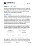
Open LPC17xx.h and search for “SCS”. Thankfully there is only one instance of SCS and as you can see it
is one of about 30 registers inside the SC_TypeDef struct. Generally, that is enough information as the
root name of the TypeDef (i.e. “SC”) is usually the symbol name assigned to it. When you get into
i
register sets that can have multiple roots like GPIO1, GPIO2, etc., you may have to do a second search to
find all of your options.
Try searching for SC_TypeDef and you will find just one instance where the symbol “SC” is defined. This
gives you a good
ood view of what is going on – all these symbols are set as pointers of TypeDef to their
respective peripheral base addresses. Now go back to the SC_TypeDef definition, and see that the
register names are simply spaced out according to their offset from tthe
he peripheral base address. Figure
2.1.2.1 shows this for the SC peripheral set and traces through all of the definitions to show how this
works.
notes_mpgl2_chapter2.docx
Release 1.1
Page 5 of 35
MPG LEVEL 2
Figure 2.1.2.1: Tracing through definitions to see how CMSIS symbol assignment works.
notes_mpgl2_chapter2.docx
Release 1.1
Page 6 of 35
MPG LEVEL 2
The #define for SC assigns the number SC_BASE and designates it to be of type pointer to SC_Typedef as
shown in #2 of Figure 2.1.2.1 (this “enforcement” is only at the compiler level). The value SC_BASE is
(APB1_BASE + 0x7C000) as shown in #3. The value APB1_BASE is 0x40080000 as shown in #4.
Therefore, the symbol SC is the number 0x40080000 + 0x7C000 = 0x400FC000. When you access
SC->register_name, you are dereferencing the pointer to one of the registers inside the SC_TypeDef. If
you look at the datasheet for the SCS register in the SC_TypeDef, you see that it is 105 32-bit words
down in the list (found by counting the number of words before SCS in the struct). The offset is thus 104
(since the first byte is at 0 offset) x 4bytes = 419 = 0x1A0. Finally, take 0x400FC000 + 0x1A0 =
0x400FC1A0 and you see that this equals the address of the SCS register as shown in datasheet (and
shown as proof in Figure 2.1.2.2).
Figure 2.1.2.2: Datasheet section showing FLASHCFG address
Source: UM10360 LPC17xx User manual Rev. 01 – 4 January 2010, NXP Semiconductors
We can summarize all that by stating that the CMSIS way to access registers is through pointers to base
addresses plus offsets defined by a register’s position in a struct. To access a particular address, you
simply dereference the pointer to the struct element using the arrow operator. In other words, to load
the value SCS_INIT into in the SCS register, the line of code is:
SC->SCS = SCS_INIT;
Obviously the definition structure takes care of the math so computing addresses never has to be done.
Bits in these registers can also be accessed with standard names. For example, the OSCEN bit in the SCS
register should be defined somewhere as SC_SCS_OSCEN. NXP defines the bit names in peripheralspecific header files, and most of the bit names can be found. However, here is another example where
the CMSIS standard was not followed exactly. First of all, OSCEN does not seem to be defined
anywhere in the NXP example files. Secondly, the header file where the rest of the registers of the
SC_Type are held are defined in clkpwr.h, and instead of “SC” as the leading label, CLKGEN is used. Still,
the OSCEN bit should be present in this file but the SCS register is not there. Under NXP’s naming, it
should be CLKGEN_SCS_OSCEN.
Though the label is missing, in general, to find the predefined BITNAME, copy the symbol name from the
data sheet and search it in the header file of the appropriate peripheral where it is found. It should
appear with the TYPE_REGISTER_BITNAME convention. If not, you might try a different header file or
notes_mpgl2_chapter2.docx
Release 1.1
Page 7 of 35
MPG LEVEL 2
accept that it is not present and define it elsewhere. As in the case of the SCS bits, the file lpc175x_.h
was created for this purpose.
After all that, we can finally enable the main oscillator and then sit in a loop until the OSCSTAT flag is set
which indicates the oscillator is ready.
void CoreSetup(void)
{
/* Turn on the main oscillator and wait for it to start up */
SC->SCS |= SC_SCS_OSCEN;
while( !(SC->SCS & SC_SCS_OSCSTAT) );
2.1.3 Clocking
With the oscillator functioning properly, it can be switched in to provide the clock source for the
processor. Understanding how the various clock sources are derived inside the MCU is very important.
For one, if you do not feed the correct clock to specific parts of the processor, some things may have
unexpected behavior (like if a clock divider is in place when you do not expect it to be) or may not work
at all (when a clock signal is turned off). The clock generation diagram shows you how the rates of all
the system clocks come to be (Figure 2.1.3.1).
Figure 2.1.3.1 LPC17xx clock generation
Source: UM10360 LPC17xx User manual Rev. 01 – 4 January 2010, NXP Semiconductors
notes_mpgl2_chapter2.docx
Release 1.1
Page 8 of 35
MPG LEVEL 2
Being able to read a clock diagram is an essential skill for an embedded designer. The diagram shows
you what signals come into the processor’s clock module and what logic they are subjected to that can
scale them in different ways. The LPC175x clock block is fairly straight forward, so let us go through it all
to ensure it is fully understood.
On the left side, there is a group of three clock signals:
1. osc_clk: the signal from the external oscillator circuit (12.000MHz in the case of this design)
2. rtc_clk: the real-time clock input (typically a 32.768kHz crystal – the footprint for this is present
on the MPG Level 2 development board but the part is not populated)
3. irc_osc: internal resistor/capacitor oscillator (generated internal to the processor with a nominal
frequency of 4 MHz)
These three signals are the main sources that the processor can use and are certainly the most common
sources found on practically any MCU. The signals are gated by a 3-channel multiplexer called the
System Clock Select that allows the processor to select which clock source it will use. By default and
after every power-up, the internal RC oscillator is selected because this is always present and will,
generally, always work even though it may vary in frequency substantially based on the operating
environment. However, it is the most reliable clock source to get the processor up and running so a
different oscillator can be selected if desired.
Whichever of the three clock sources is selected, the signal is split and either feeds the device’s PLL
(phase lock loop) or is fed directly to a second mux, the CPU PLL selection mux. A PLL is an interesting
device that up-converts clock signals into faster clock signals. PLLs are everywhere these days, and are
found in most radio systems for converting a slow baseband frequency to a fast radio frequency (the
ANT AP2 IC uses an internal PLL to up-convert the 16MHz signal to 2.45GHz). The input to a PLL must be
very stable (usually a crystal oscillator or better) and the output of a PLL is adjustable, though usually
only up in frequency. The reason the PLL is on the LPC175x is so a slower crystal can be used but the
system can still generate faster frequencies for certain device functionality like USB. The system could
run at this speed all the time, or it could change the PLL output to run at different frequencies at
different times. Slower operating speeds always consume less power, and crystals in the range 4-20MHz
are less expensive and widely available.
From the output of the sysclk, another mux selects whether to use the PLL or direct sysclk signal, and
this signal is labeled pllclk. pllclk runs into the CPU clock divider which can scale the clock signal down
based on the value in the CCLKCFG register (anywhere from 1 to 256). Since 12MHz is plenty fast for the
system and we do not have any USB functionality, we will save power by not running the PLL and
sticking with a 1:1 divider to give us the core clock, cclk.
notes_mpgl2_chapter2.docx
Release 1.1
Page 9 of 35
MPG LEVEL 2
Notice the other USB-related blocks in the upper half of the clock diagram. The USB has a dedicated PLL,
or the USB clock can be derived from pllclk through its own divider. The mux USB PLL chooses between
the two and gives usb_clk.
While the core will use cclk, each peripheral requires a clock source as well. Every peripheral has four
options of cclk scaling (1:1, 1:2, 1:4 and 1:8). This can help to save some power depending on what the
peripheral has to do and often the system performance does not suffer since the core is usually doing a
lot more work that a peripheral. Therefore the default value of 1:4 scaling will be kept for now, though
the registers PCLKSEL0 and PCLKSEL1 will still be initialized. Each peripheral clock is called
PCLK_PERIPHERAL_NAME.
Lastly, there is the watchdog clock source selected with the watchdog mux. Since a crystal oscillator can
fail and one of the main purposes of a watchdog reset is to save a system whose oscillator has stopped,
osc_clk is not one of the options for clock the watchdog system. Either rtc_clk, irc_osc or PCLK_WDT (a
dedicated watchdog clock) can be used to provide wd_clk.
Since various calculations in the rest of the development will use these clock names, it is handy to do
two things:
1. Keep a printout of the clock diagram and label it with the frequencies and divider values that
have been set
2. Create some constant definitions with the values for the frequencies and dividers.
2.1.3.1 Implementing the clock setup
Now that all of the details and requirements for the clocking system are understood, the code to
implement the settings can be written. Setting all of the registers is straightforward and because so
many defaults can be used, only two registers end up needing configuration. The INIT values for each of
the registers of interest will be defined and then simple assignments are used to load the values to their
respective locations. What the INIT values need to be is determined by patiently reading the register
descriptions in Chapter 4 of the LPC user guide. Check out the completed code in the header and source
files of CoreSetup () and be sure to understand the choices and implementation.
2.2 System Diagram and Power Control
Once the processor is running, a simple main loop with the correct clock source and the peripheral
drivers to enable the device can start to be added add in. Again, depending on the processor, activating
a peripheral may involve a few different steps. In simple MCUs, the supporting hardware may be ready
to go as soon as the particular peripheral registers are initialized. In other MCUs like the Cortex-M3
parts, there are often several different registers that need to have certain bits set to run a peripheral
including the clock source and power or enable bits.
notes_mpgl2_chapter2.docx
Release 1.1
Page 10 of 35
MPG LEVEL 2
The system diagram (Figure 2.2.1) can sometimes help you to understand how everything is built onto
the microcontroller and how different parts of the device interact.
Figure 2.2.1: LPC17xx block diagram
Source: UM10360 LPC17xx User manual Rev. 01 – 4 January 2010, NXP Semiconductors
notes_mpgl2_chapter2.docx
Release 1.1
Page 11 of 35
MPG LEVEL 2
AHB stands for Advanced High Performance bus. To find out what that really means, read through the
ARM and NXP documentation and figure out many of the low-level details. The basic meaning is that it
is interconnect wires that link all the peripherals to the main core in the fastest way possible. One of the
wires will be a clock source, so you must be aware if a particular processor has more than one peripheral
bus as there may be different bits in different places to activate clocks to certain peripherals. That being
said, the LPC17xx does split the peripherals into two groups, but there is not any distinction between
the two worth noting at this time.
2.2.1 Flash Accelerator
Notice the Flash Accelerator block between the AHB matrix and the Flash memory. Reading flash
memory is relatively slow (and writing flash memory takes forever, comparatively) so if the core is
running above 20MHz, then the flash cannot provide information fast enough. If the flash is too slow for
the processor core, wait states are required which is all controlled by the Flash Accelerator block. There
are some more details in Chapter 5 of the user guide and since it is only a few pages it is worth reading
to gain a bit more understanding about what the core must actually put up with.
The course hardware runs at 12MHz thus no wait cycles are required. Therefore, the default setting of
1:4 to 1:1 can be changed by clearing a few bits in SC-> FLASHCFG.
2.2.2 Power Control
The last thing to configure in the system core is power control. There are two registers here that do
different things. The first, PCON, controls the power modes of the core and this will be very important
to us very shortly for putting the processor to sleep. The second, PCONP, controls power/clocks to each
peripheral and this is our concern right now.
As mentioned earlier, every peripheral can be turned on individually so that only those needed in the
system will consume power. On some processors, even the GPIO ports have to be individually enabled.
As the various modules of a design are programmed, peripherals required can be activated. A single
write to PCONP is an efficient way to set this up. All the bits are mapped out in development.h so it will
be relatively easy to turn peripherals on as they are programmed into the system. Right now, the value
PCONP_INIT that is defined has every peripheral turned off. This setup value will be revisited
throughout the course as peripherals are required to be activated. Though all the active peripherals
could be figured and activated now, enabling them as they are used helps to emphasize the point. The
process is again very simple, but the effects are critical.
A really important note to make: if you are ever debugging a peripheral problem during development
and even simple writes to registers do not seem to have any effect (the register contents stay zero), it is
very likely that the peripheral clock and/or power have not enabled with a bit that may be nowhere near
the other peripheral configuration bits. Though the peripheral itself may have a separate enable bit,
nothing will happen if the clock or power from the core is not connected.
notes_mpgl2_chapter2.docx
Release 1.1
Page 12 of 35
MPG LEVEL 2
You may start to notice that the order of these notes and corresponding setup that is taking place is the
same order in which the reference guide for the processor is organized. These steps are truly the
essentials to getting up and running on a processor, so it makes since that the information is presented
this way. Kudos to NXP for structuring their documentation like this – other processor manufacturers
jump around more and can result in missing some important register configurations.
2.3 Interrupts
With a reasonably solid understanding of interrupts from MPG Level 1, we can dive right in to interrupts
on the LPC175x without covering all of the background information. However, a fair amount of time will
be taken to discuss the details of actually implementing interrupts on the NXP processor since it is such a
fundamental, important concept. If you do not have previous experience or equivalent experience
implementing interrupts on another processor, it is highly recommended that you review MPG Level 1
Chapter 9. The interrupt controller on the LPC175x processor is actually easier to use than on the
LPC214x family. However, both are more complex than lower-power 8 and 16-bit processors.
That being said, we will start by taking a bit of time reviewing the fundamentals of interrupts that apply
to any embedded system. The idea itself is simple: any event that needs immediate attention grabs the
program counter to execute a special function called an interrupt service routine (ISR) or interrupt
handler, runs the ISR, then returns the program counter to the location where it was “stolen” from in
the first place. The program then continues its normal progression through the code in flash and has no
idea that it was temporarily suspended while other code executed.
The key concepts are:
1. An interrupt source must be configured and enabled in order to provide an interrupt signal to
the interrupt controller. If the interrupt is not enabled, the interrupt signal (flag) will still be
asserted with the event, but the signal will not be propagated to the interrupt controller and the
ISR will not execute. However, the signal can be polled instead, so you can use the logic of the
interrupt in a more controlled/predictable fashion to trigger events.
2. There is almost always some sort of global interrupt enable (GIE) that must also be set to allow
any interrupts to be active. If the GIE is disabled, the individual interrupt signal will still be
present and an interrupt will be triggered if the GIE is later enabled (as long as the signal has not
been cleared). The GIE is called different things depending on the processor. ARM has not
included a traditional GIE bit on Cortex-M3 processors that can be accessed at any time, but it is
instead protected and generally not used frequently. Instead, each interrupt source is
individually enabled / disabled.
3. When an interrupt occurs, an ISR is called automatically based on the source of the interrupt.
Generally every interrupt source can have a unique ISR.
4. On the LPC17x processors, priorities are available for all interrupt sources. Any time an enabled
interrupt source occurs that is a higher priority than an interrupt already active and running its
notes_mpgl2_chapter2.docx
Release 1.1
Page 13 of 35
MPG LEVEL 2
5.
6.
7.
8.
9.
ISR, the processor will stop execution and switch to the higher priority interrupt. In this way, the
Cortex processor can “nest” up to 256 interrupts levels, thus the name “Nested Vectored
Interrupt Controller.”
Active interrupts of the same hardware priority can be further prioritized in firmware, so even if
two interrupts occur simultaneously, the higher priority interrupt can be serviced first.
An interrupt source can occur even if its ISR is executing. Since interrupts of the same priority
level are disabled while an ISR runs, the new interrupt event will not have any impact until the
current ISR exits. The interrupt signal will trigger another call to the ISR as soon as the
interrupts are re-enabled as the ISR exits. The Cortex processor refers to this as tail-chaining
and recognizes it to avoid restoring and re-saving the processor context which saves valuable
processor cycles and thus speeds up interrupt latency time.
An interrupt can occur at any time and in any place in the code (as long as the required interrupt
enable bits are set). This means the program must be able to survive being interrupted at any
point. If there are places where the program simply cannot survive if it is interrupted, then
interrupts must be disabled during that part of the code – a handy use of the GIE bit if it is
available. Since no GIE bit exists on the Cortex parts, one must be a bit more careful to ensure
that all interrupt sources that could impact the critical code are disabled.
When an interrupt occurs, the program “context” needs to be saved so that resources can be
used to execute the ISR code without destroying values in locations that maybe overwritten
during the ISR. On the Cortex-M3, the program counter, processor status register, link register
and the registers r0-r3 and r12 are all automatically saved (this costs 12 processor cycles in
latency between the interrupt occurring and the ISR starting). If you use other resources that
are shared in the main code and ISR, then those resources must be saved as well. For example,
say you have a scratch register “temp” that you use all the time for temporary storage. If the
ISR uses “temp” as well, then it must be saved first and restored on exit.
An ISR should execute as quickly as possible. When complete, the system context must be
restored. The Cortex automatically restores the registers it saves and the function returns and
re-enables the interrupt source that was suspended during the ISR execution.
When talking about interrupts, the term “exception” often pops up – even in the NXP documentation.
NXP implies that interrupts are a subset of exceptions, which may not be exactly correct depending on
what definition you read. Though both will cause the program counter to vector to a particular handler
address, the reason the program counter moves is where the distinction occurs. The preferred
classification is that exceptions arise from “faults” that come about from code that is running. For
example, bad memory accesses and divide-by-zero operations. Interrupts, on the other hand, are
desired signals that you want to capture and respond to. They are asynchronous to the normal program
flow (i.e. they can occur at any time and any place), and ISRs are in place because the interrupt is
expected to occur. Examples include GPIO signals, timers, bytes arriving in serial peripherals, etc.
notes_mpgl2_chapter2.docx
Release 1.1
Page 14 of 35
MPG LEVEL 2
2.3.1 Interrupts on the LPC175x
Even with just this basic understanding of interrupts, we can take a look at getting them up and running
on the LPC175x processor which should, ultimately, fully bring you up to speed. As with any new
peripheral you want to learn, you should start by reading the appropriate section in the datasheet. Do
that now, even if you do not understand everything you read. As an embedded designer, this is the
approach that you typically have to take. Since much of the interrupt functionality takes place entirely
on the Cortex core, a lot of the specific details are not included in the NXP documentation and instead
are found in the Cortex-M3 documentation from ARM. If you would like to learn more about how the
NVIC operates, check out these two documents that are linked on the course website:
1. Cortex-M3 Technical Reference Manual r2p0
2. ARMv7-M Architecture Reference Manual
So far all we have in our source code is the interrupt vector table in startup_LPCxx.s that is a bunch of
memory locations loaded with the addresses of the interrupt service routines (handlers) that are called
when the interrupt happens. Adding the functionality to configure and enable those interrupts is what
comes next.
Table 50 in the NXP reference manual is important as is lists all of the interrupts available to the
processor and indicates what flags (sources) can trigger each main interrupt source (see Figure 2.3.1.1).
You may want to print this table for the course bible, though you will not refer to it too often after initial
setup.
There is a handler in startup.LPCxx.s corresponding to each of these interrupt IDs. For example,
interrupt source 5 is the UART0 peripheral interrupt. If this interrupt is triggered, then the UART0
handler is called. Since there are six different flags, the ISR must parse out which interrupt signal in the
UART0 peripheral caused the interrupt. It is up to you to prioritize which flag is checked first and thus
gets attention first. Once the particular flag is cleared, the ISR will exit. If another flag was also set, the
UART0 handler would be re-entered immediately at which time your code would parse through and find
the next flag that was set to handle it.
ISRs only need to be written for interrupt sources that are enabled, though robust firmware could
include code that handles all interrupt sources to ensure the code does not get stuck if an unexpected
interrupt gets enabled and triggered.
notes_mpgl2_chapter2.docx
Release 1.1
Page 15 of 35
MPG LEVEL 2
Figure 2.3.1.1: Interrupt sources
Source: UM10360 LPC17xx User manual Rev. 01 – 4 January 2010, NXP Semiconductors
notes_mpgl2_chapter2.docx
Release 1.1
Page 16 of 35
MPG LEVEL 2
The reference manual talks about remapping the interrupt vector table, but that will not be done for the
course. Remapping simply adds an offset to the location loaded in the program counter when an
interrupt occurs so the vector table can be stored elsewhere in memory but still operate the same way
as far as the programmer is concerned. The primary reason for moving the interrupt table would be to
allow a custom boot loader to be stored at the beginning of flash space, with the main code stored
beyond that. Firmware can be written to upgrade itself where the first part of code is a simple program
for erasing and reloading the rest of the code (from an external flash memory, for example). The
firmware update would need to update the interrupt table, so it would have to be in the part of code
that the boot loader erased and reloaded. The table can also be moved to RAM which could allow a
performance improvement if the processor was running at a high clock speed and flash accesses were
slower.
2.3.1.1 LPC175x NVIC registers
From our knowledge of interrupts, we know that interrupt configuration requires the following (roughly
in this order):
1. Identify the interrupt sources to use
2. Setup the NVIC registers to tell the NVIC what interrupts it should pay attention to and what
priorities they will have
3. Enable the selected interrupts
4. Write interrupt service routines to handle the enabled interrupts
All interrupt-related code will live in interrupts.c and interrupts.h. These files are part of the Chapter 2
End package on the course website. As this firmware platform comes together, there will be quite a few
different interrupts that are set up and running to provide the system functionality. In the design phase
you would want to consider what interrupt sources will be used and make some initial decisions on the
priority of those sources even though some adjustments might be made later on. Some of the interrupt
registers can then be set up though until the code is written that will ultimately make those interrupts
active, the enable bits can be kept off. Interrupts required for this application in order of highest to
lowest priority are as follows:
1. System tick: a one-millisecond timer that is used to keep a count of system time. This needs to
be set as the highest priority to ensure that system timing is bang-on.
2. ANT chip-select line: ANT indicates a message is ready through a GPIO line to the LPC processor.
To avoid any possible buffer overflows in the ANT subsystem, this interrupt will be given the
next highest priority.
3. UART RX: Incoming communications line from the debug serial port that indicates a byte has
been received.
notes_mpgl2_chapter2.docx
Release 1.1
Page 17 of 35
MPG LEVEL 2
4. I²C TX: Outgoing communications line to the LCD module where screen data is sent. Very long
messages (up to 8k for an entire screen refresh) are queued and then handed off to the
interrupt mechanism to send out all the data while the processor does other things. Every time
a byte is sent, the interrupt fires to load up the next byte in the queue for transmission.
5. Button inputs: the four-axis of the trackball and 3 momentary switches will use interrupts to
signal the processor.
The priorities are assigned based on the importance of the signal and the nature of the input source.
Devices like ANT and the debug UART generate “unsolicited” messages. That is, the host processor does
not need to take any action for messages from ANT or the debug port to arrive. These sources are
therefore given highest priority to minimize any chance of losing data. While buttons are also
unsolicited data inputs, they are at a much lower data rate since they are human inputs and are also just
1 bit in length with no subsequent data. They can be low priority as the chance of missing an input is
virtually nil, especially since there is a long debounce period on them anyway. However, all GPIO input
interrupts use the same interrupt signal to the NVIC, so the buttons will end up at the same priority level
as the ANT chip-select.
Interrupts from sources where the processor has initiated the data transfer are the next level of priority.
Data can be transferred very quickly, but because the MCU is expecting it, it can be managed more
easily. For example, any I²C transfer to the LCD is entirely controlled by the host. The LCD does not care
how often bytes arrive, so it does not matter if the MCU is a bit late queuing up the next byte in a
sequence because it is busy servicing a higher priority interrupt.
With this information in hand, we can write the setup code for the interrupts. The registers in the NVIC
are easy to understand:
•
ISERx / ICERx to set and clear specific interrupt sources. All interrupt sources are off by default
and will remain off for now since we have not reached the point where they are ready to be
active.
•
ISPRx / ICPRx to manually set interrupts (if required), for determining what sources are active,
and for clearing the active bit. ISPRx is the register you would read if you were using an
interrupt source “manually” – i.e. polling the interrupt flag for an event even though the
interrupt was not active.
•
IABRx indicates which interrupt sources are active (not sure why this is different than pending)
•
IPRx are the priority set registers where the priority of each interrupt is selected.
Of these registers, the priority registers can be setup and hooks for ISER will be written so that bits can
be flipped in the configuration file to enable interrupt sources as they are required. The CMSIS access
for the interrupt registers make use of array indexing since the definitions are intended to support all
notes_mpgl2_chapter2.docx
Release 1.1
Page 18 of 35
MPG LEVEL 2
families of Cortex parts and thus there can be quite a few registers of the same base name. For
example, there are nine priority registers IPR0 through IPR8, so the CMSIS access to the ith register is
NVIC->IPR[i].
IPRx_INIT values are defined in interrupts.h where the four interrupt sources of interest are assigned
priorities and all other interrupt sources are set as the lowest priority. Since there are eight priority
registers, the init values are setup in an array and loaded with a loop. A type cast is required inside the
loop so the compiler knows how to index the IP array properly.
void InterruptSetup(void)
{
u32 au32PriorityConfig[] = {IPR0_INIT, IPR1_INIT, IPR2_INIT, IPR3_INIT, IPR4_INIT,
IPR5_INIT, IPR6_INIT, IPR7_INIT, IPR8_INIT};
/* Set interrupt priorities */
for(u8 i = 0; i < PRIORITY_REGISTERS; i++)
{
((u32*)(NVIC->IP))[i] = au32PriorityConfig[i];
}
/* Enable interrupts */
NVIC->ISER[0] = ISER0_INIT;
NVIC->ISER[1] = ISER1_INIT;
} /* end InterruptSetup(void) */
A close look at the priority settings and enable bits reveals that there is no reference to the System Tick
timer interrupt, and in fact the ANT/GPIO interrupt has been assigned priority 0 (the highest interrupt
priority). This is because the Cortex-M3 has a built-in system tick timer that is part of the core
exceptions and thus higher in priority than any configurable interrupt. To find the details of the system
tick, look at the Cortex-M3 Technical Reference Manual.
Loading and enabling interrupts always occurs in the main program after all of the peripherals are set up
but before any application initializations that will expect their interrupt resources to be ready for use.
Turning on interrupts before the peripherals from which they are sourced will probably result in
undesired spurious interrupts.
2.3 System Timing and Sleep
From this point on, the processor reference manual will no longer be followed in order. The information
needed for each new peripheral will be found in specific chapters which can be referenced as required.
The next peripheral to activate is the system tick – chapter 23 in the reference guide.
notes_mpgl2_chapter2.docx
Release 1.1
Page 19 of 35
MPG LEVEL 2
2.3.1 System tick
Timing in the system will be kept with the core system tick timer that will be configured to count
millisecond periods. The ISR will then be set to keep a running count of these periods in a 32-bit global
variable, GGu32SysTime1ms. Another 32-bit global, GGu32SysTime1s, will count elapsed seconds. The
device will not know the actual time and date but will instead base timing information from a reference
of 0 time when the whole system starts up. It would be easy to track the actual time and date using the
real-time clock peripheral, but since the system does not need this information, there is no point in
doing it.
The overflow period of GGu32SysTime1ms is just over 49 days, and GGu32SysTime1s is good for over
136 years! It is safe to say that no attention to handle system time overflows is required as it is fairly
unlikely that someone will play Pong continuously for 136 years on their device.
The system tick timer is similar to any other timer peripheral except that it is built into the Cortex core.
The main purpose of its existence is for use with an operating system where the process time can be
clocked with the system tick (10ms is the nominal value discussed in the data sheet). It can be
reconfigured as required by writing to the correct setup addresses. To use a custom value with certain
versions of code from IAR, a setup routine in core_cm3.c might need to be overridden by changing the
value of a define in LPC17xx.h to 1:
#define __Vendor_SysTickConfig
1
/*!< Set to 1 for different SysTick Config */
Beyond that, setup is straight forward with just two registers required. Since this functionality is closely
coupled to the development board, the source code will be in development.c with the interrupt handler
in interrupt.c.
void SysTickSetup(void)
{
GGu32SysTime1ms = 0;
GGu32SysTime1s = 0;
SysTick->LOAD
= (u32)SYSTICK_COUNT;
SysTick->VAL
= (0x00);
/* Load the SysTick Counter Value */
SysTick->CTRL
= SYSTICK_CTRL_INIT;
} /* end SysTickSetup(void) */
void SysTickHandler(void)
{
static u16 u16SecondCounter = 1000;
/* Update the 1ms system timer */
GGu32SysTime1ms++;
/* Update the 1 second timer if required */
notes_mpgl2_chapter2.docx
Release 1.1
Page 20 of 35
MPG LEVEL 2
if(--u16SecondCounter == 0)
{
u16SecondCounter = 1000;
GGu32SysTime1s++;
}
/* Clear the interrupt flag */
SCB->ICSR |= SCB_ICSR_PENDSTCLR;
} /* end SysTickHandler(void) */
The definition for SCB_ICSR_PENDSTCLR must be added to lpc175x_.h (this register bit is defined on
page 170 in the Cortex Technical Reference manual).
2.3.2 Sleep
Managing power consumption in an embedded system is always important as saving power is always
good. The ANT radio system is specifically designed to consume as little power as possible which is one
of the reasons why it stands out so well from its competition. Many ANT systems can maintain an
average current in the uA range even while maintaining a data connection to another device.
Microcontrollers typically have several sleep modes where different parts of the MCU are put to sleep.
These can range from just shutting down the core and leaving peripherals running, to completely turning
off the device other than some basic logic to wake up the processor.
The course system will make use of two of the Cortex-M3 low power modes:
1. Sleep mode: the core clock is stopped but all peripheral functions continue to operate. Any
interrupt will wake the processor back up. Wakeup takes only a few cycles, so the system can
respond quickly to any event.
2. Deep sleep mode: practically everything in the microcontroller is shut down. The processor can
only be woken up in certain ways, including external interrupts. In this mode, the system will
rely entirely on the ANT subsystem to wake it back up so it can process gaming instructions,
perform any user interface updates, then go back to sleep. The disadvantage of Deep Sleep is
that it takes about 4096 instruction cycles to start back up (341us), and all of the clock
configuration must be repeated with each wake up. This creates substantial latency in the
system, though for our device the timing is still insignificant.
Deep Sleep is a bit more challenging to implement successfully and there is some further information to
explore to fully understand what options are available, what state the processor will be in, and what the
wakeup requirements are. Therefore, it will be left for an advanced exercise, though all the design up to
that point will be done keeping the needs of Deep Sleep in mind.
notes_mpgl2_chapter2.docx
Release 1.1
Page 21 of 35
MPG LEVEL 2
For now, two registers need to be loaded to specify that the processor enters sleep mode when
requested using the intrinsic function WFI(). PCON configuration is added to CoreSetup(), and the
function SystemSleep() is added in development.c where the write to the System Control Register is
performed (later this write will be conditioned on what power-down mode is desired).
void SystemSleep(void)
{
/* Set the system control register for Sleep (not Deep Sleep) */
SCB->SCR &= ~SCB_SCR_SLEEPDEEP;
/* Now enter the selected LPM */
__WFI();
} /* end SystemSleep(void) */
2.4 Watchdog Setup
The Watchdog timer is implemented to help mitigate any firmware problems that may result in the
code getting stuck somewhere. Stuck code can result for numerous reasons including on-purpose
infinite loops meant to hold code in a place that it “should” never get to (this is more for development
purposes, since holding code doing nothing is not useful to a user), unexpected infinite loops from
coding errors, or unexpected infinite loops conditioned on signals that may never happen.
Like any other timer, the watchdog counts down and will do something when it reaches 0. Unlike other
timers, the watchdog has the power to reset the processor. The intended implementation is to never let
the watchdog reach 0 by always reloading it. It also has a dedicated clock source separate from the
main oscillator so it can still operate if the main clock dies. When the processor is reset, it restarts on
the internal oscillator and will try to restart the crystal. A fully complete system would handle the case
when the crystal will not restart (likely the case if the watchdog reset the processor in the first place). If
the internal oscillator fails, then even the watchdog will not be able to save it, but the chances of that
happening are close to zero. It is not so uncommon to have a crystal fail, especially if the device is
subject to extreme temperatures or vibration.
To configure the watchdog, four registers are loaded. The source code is placed in development.c and
development.h as this is a board-level function. Since the watchdog is a system-critical peripheral, the
peripheral registers are protected in several ways:
1. Any changes to the watchdog mode register will not take effect until the watchdog is “fed.”
2. Once the watchdog timer is enabled through software, it cannot be disabled.
3. The watchdog clock source selection register contains a bit that can be set to lock off any access
to the watchdog registers.
notes_mpgl2_chapter2.docx
Release 1.1
Page 22 of 35
MPG LEVEL 2
4. To reset the watchdog timer and to latch any changes to WDMOD, a “key sequence” must be
written to the watchdog feed register. The key sequence is 0xAA followed by 0x55 to WDFEED.
This will cause the processor to reload the watchdog with the value in WDTC.
To choose the timeout duration, the WDTC register is loaded with a value that will be used to reset the
counter. The watchdog timer has a built-in 1:4 prescaler and the internal oscillator is 4MHz nominal and
4.04MHz max. For a minimum 1 second watchdog timeout, the watchdog counter must be set at
1,010,000. This value is reloaded to the counter every time the feed sequence is executed.
void WatchDogSetup(void)
{
WDT->WDCLKSEL = WDT_WDCLKSEL_INIT;
WDT->WDTC
= WDT_COUNTER;
WDT->WDMOD
= WDT_WDMOD_INIT;
ThrowBone();
} /* end void WatchDogSetup() */
Activating the watchdog is done at the end of the device initialization period just before interrupts are
enabled. At this time, the system is expected to be running smoothly and the regular watchdog timer
resetting can begin. Note that most embedded designers tend to have their own amusing term used to
reset the watchdog timer. This system uses “ThrowBone()” to keep the dog happy.
As a last note, mistakes can be made when configuring the watchdog timer such that the processor will
be stuck trying to reset. This will cause the JTAG debugger to be unable to connect to the core to halt it.
If this occurs, correct the erroneous code and start up the development board in boot loader mode
before trying to reattach the JTAG. For extended troubleshooting, disable the watchdog reset in
WDMOD and just use the interrupt until the source of the error is found.
2.5 GPIO Setup
Finally the system is ready to start doing some configuration that will actually be visible on the output.
GPIO setup loads all of the data direction registers, sets the pin functions, and puts the initial starting
conditions on the output lines. This setup source code is in development.c and development.h.
CMSIS access to GPIO registers are as follows:
1. Pin mode selection: Set the PINSEL registers per the PINSEL tables in the reference guide. To
load the values use:
PINCON->PINSELx = PINSELx_INIT
notes_mpgl2_chapter2.docx
Release 1.1
Page 23 of 35
MPG LEVEL 2
2. Pin driver configuration: Set the PINMODE registers to select pull-up, floating, or pull-down. To
load the values use:
PINCON->PINMODEx = PINMODEx_INIT
3. Pin open drain config: Set the PINMODE_OD registers to select open drain or push-pull driver.
To load the values use:
PINCON->PINMODE_ODx = PINMODE_ODx_INIT
4. Data direction: Set the FIODIR registers to select input / output configuration of the pin To load
the values use:
GPIOx->FIODIR = FIOxPIN_INIT
5. Initial values: Set the FIOPIN registers to select the logic start state for output pins. To load the
values use:
GPIOx->FIOPIN = FIOxPIN_INIT
Most of the work involved with configuring GPIO comes with defining the setup values. These
definitions are done bit-wise in development.h and then loaded to the processor during setup. It takes
several hours to map out all the configurations and assign them to initialization values, but doing them
this way gives clear visibility to how every GPIO is configured and makes it easy to make changes should
the need arise.
An important note: when testing the GPIO configuration, it was discovered that writes to the PINCON
block worked correctly but any write to GPIOx registers did not work. As stated earlier during
configuration of the power control / peripheral clock activation, when processor registers are being
written in firmware but the debugger shows that no changes are made, it strongly suggests that either
the power or the clock to that peripheral is disabled. The NXP datasheet clearly states that the GPIO
peripheral is always powered, and nowhere in the documentation is there any mention of power control
bits. However, the symptoms pointed toward a power enable bit, so further investigation of the PCONP
register was conducted.
Using the debugger register window, it was found that there is indeed a GPIO enable bit in the PCONP
register as shown in the highlighted bit location in Figure 2.5.1. As a test, this bit was set to 1 using the
debugger, and that enabled the GPIO so writes to the GPIOx-> registers worked properly. This bit was
traced to bit 15 and the PCONP initialization value was updated which allows GPIO to work properly. If
not for recognizing the symptoms of the problem, this likely would have cost several hours of
troubleshooting and eventually some correspondence with NXP tech support. The lessons learned are
that everyone makes mistakes and trust your experience.
notes_mpgl2_chapter2.docx
Release 1.1
Page 24 of 35
MPG LEVEL 2
Figure 2.5.1: The mysterious PCGPIO bit
The latest version of the processor documentation has this error corrected. This is a good reminder that
everyone is human and anyone can make mistakes. Since most of the time mistakes will probably be
your own, you should thoroughly investigate problems to understand them as much as possible prior to
contacting technical support. If you are convinced that what you are doing is correct, it still pays to be
open-minded when discussing the issue with someone else.
Once the GPIOs have been configured, setting bits in registers should be done with the FIOSET register;
clearing bits should be done with the FIOCLR register. However, GPIO access can also be performed
through FIOPIN for reading and writing to the whole port.
2.6 LEDs
LEDs are fairly simple to understand as basic output indicators: if the LED is active-high and the GPIO line
attached to an LED is high, then the LED will be on. For simple systems this is all you have to worry
about, but what happens as your system starts to get more complicated? As an example, consider the
act of blinking an LED. The very basic loop structure is:
while(1)
{
Toggle LED
Wait blink time
}
notes_mpgl2_chapter2.docx
Release 1.1
Page 25 of 35
MPG LEVEL 2
Simple enough. If you want to blink more LEDs at different rates, you can set up more counters. Until
you have many, many LEDs, adding a counter for each and handling it individually is not that big of a
deal. What happens, though, if you start having several different applications wanting to use the same
LED? For example, maybe the yellow LED needs to be used to indicate that a button is pressed, but it
also needs to show that communication is taking place by blinking at a certain rate or toggling every
time a byte is received. If both applications have control of the LED, then they will fight and the desired
functionalities will conflict resulting in garbage output to the user.
As another example, what if an LED is in a blinky state with one application, and another application gets
to a point where it needs to turn the LED on solid for a while. Since applications often do not have any
knowledge about each other, when the second application is done keeping the LED on solid it may just
turn it off. If the first application was not looking to see if its LED got turned off (why would it, since it
does not know any other programs exist?), it may continue operating with the belief that the LED is still
blinking when it is not. Indeed, the application could have code added that would take care of this, but
it certainly does not solve all the potential problems. Though there are not necessarily going to be any
circumstances where the Pong system needs to multiplex the meaning of an LED, it could certainly take
place in a more complicated device that may have several functions multiplexed to only one or two
LEDs.
So in general, any time a resource is shared, you have to think about how the users of that resource are
going to play together. This applies to memory resources, communication resources, and of course
simple device resources like LEDs.
To combat that problem an LED application can be used to supply a controlled interface to the
hardware. This provides the important first step of abstracting the LED functionality into its own
application and forcing other applications to communicate to it if they want to use the LED resource. To
help manage LED conflicts, the LED application will provide two levels of priorities for the LEDs so that
other applications can manage use of the lights without overwriting each other. Higher priorities will
pre-empt the lower priorities, but the low-priority state will be saved so it can be restored once the
higher-priority application is finished.
As a starting point, two new files are created: led.c and led.h. These files will hold the majority of the
LED code including the low-level drivers for toggling the correct pins and the higher level state machine
code that will be running to manage the task of blinking.
notes_mpgl2_chapter2.docx
Release 1.1
Page 26 of 35
MPG LEVEL 2
2.6.1 LED State Machine State Diagram
Figure 2.6.1.1 shows the state diagram for the LED SM.
Figure 2.6.1.1: LEDSM State Diagram
LEDInitialize occurs only on power up to setup registers and run a quick visual test of the LEDs.
Idle() monitors a countdown to put the LEDs to sleep (turn them all off) for power savings if there is no
button activity. Applications can change the state to Blinky() if they make a blinking LED Request.
Blinky() manages the timing for the blinking LEDs. The LEDs can go to sleep even if they are blinking. If
all applications that have Requested blinking LEDs release the LEDs, then Idle() is resumed.
2.6.2 LED Functions and API
The core private driver functions take care of toggling the correct lines to turn on and off each LED. The
functions are setup with certain assumptions about what GPIO port the LEDs are on to minimize code
space, but this can easily be modified to account for LEDs on any GPIO.
notes_mpgl2_chapter2.docx
Release 1.1
Page 27 of 35
MPG LEVEL 2
/* Private functions */
u32 LEDGetLEDBitLocation(LEDNumberType);
void LEDSet(LEDNumberType);
void LEDClear(LEDNumberType);
void LEDToggle(LEDNumberType);
void LEDUpdate(LEDNumberType);
/*
/*
/*
/*
/*
Return the pin/bit location of the LED */
Turn on an LED */
Turn off an LED */
Toggle an LED */
Refresh LED based on current settings */
The two main API functions for other applications to gain access to LEDs are LEDRequest() and
LEDRelease(). The calling application must provide its Requester ID and specify parameters of the LED it
wants to control. Once the application is done with an LED, it must release it.
/* Public functions */
void LEDRequest(LEDSetType*);
void LEDRelease(LEDSetType*);
/* Request for control of an LED */
/* Release control of an LED */
Currently the system handles only two priorities of LED requester. If two levels of LED requester
priorities have already requested an LED and a third LED requester of higher priority requests the LED,
the lowest priority requester will not be restored after the two higher priority requesters have released
the LED. The functions are written so any call to LEDRelease() by a requester who was bumped off the
queue will still complete gracefully.
It would be a simple task to expand the system to allow more levels, perhaps one for every requester
type so that no LED state would get lost. The value in doing so could be debated as it is likely that the
system will rarely require more than two levels of LED history.
2.6.3 LED Typedefs
To help keep the code looking organized and self-documenting, the LED driver makes several
enumerated type definitions:
typedef enum {LED0, LED1, LED2, LED3} LEDNumberType;
/* LED Requester Priority List: lowest number = lowest priority */
typedef enum
{
LED_REQUESTER_FREE,
LED_REQUESTER_BUTTONS,
LED_REQUESTER_ANT,
LED_REQUESTER_USER
} LEDRequesterType;
typedef enum
{
LED_OFF, LED_ON, /* These two must be the lowest value entries */
LED_0_5HZ = 1000, LED_1HZ = 500, LED_2HZ = 250,
LED_4HZ = 125, LED_8HZ = 63
} LEDBlinkRateType;
notes_mpgl2_chapter2.docx
Release 1.1
Page 28 of 35
MPG LEVEL 2
typedef struct
{
LEDNumberType eLED;
LEDRequesterType eRequesterID;
LEDBlinkRateType eBlinkRate;
} LEDSetType;
LEDNumberType provides a shorthand to each LED and orders them in incrementing value that will be
used by different LED functions. LEDs can easily be added or removed if the design changes or if the
code is ported to a new design.
Priorities are assigned in the LEDRequesterType simply by the order that the requesters are defined.
This allows priorities to be changed easily if required, and again allows for easy addition or deletion of
requesters.
To keep multiple LEDs blinking consistently can actually be a bit of a challenge in a busy system. The
approach to blinking is to choose set periods that LEDs are allowed to blink at. The rates provided offer
a good mix of toggling rates that can be observed by the human eye. Notice that the OFF and ON states
are part of the type definition implying that the function that uses the enumeration will not need special
cases for fully on or fully off LEDs.
Finally, a struct is used to group all the relevant LED parameters into one bundle. This helps users
ensure that they always include the correct information when making function calls.
2.7 Buttons
There are three mechanical buttons in this system that can be toggled by a user. Like the LEDs, a button
system was designed that is easily scalable and can provide all the functionality required of a button
with little effort. All of the button source code will be captured in buttons.c and buttons .h.
Detecting button presses is trivial, and both a polling solution and an interrupt driven solution work well.
There are quite a few advantages to using the interrupt method including instantaneous response and
the ability to wake up from sleep when a button interrupt occurs.
In addition to detecting that the button has been pressed, there are two functions involved with buttons
that can be slightly irritating to implement: debouncing and hold detection. Both of these functions
require timing and polling of the button input to ensure the button status is accurately captured and
reported to the system. The button system for the course uses interrupts to detect initial button state
changes – both when the button is pressed and when the button is released. As soon as a button
interrupt occurs, that interrupt is disabled and monitoring of the button is picked up by the button state
machine. The state machine times the debounce period and then checks to see if the new button state
notes_mpgl2_chapter2.docx
Release 1.1
Page 29 of 35
MPG LEVEL 2
is still present. If it is, the button state is considered changed and the interrupt is re-enabled. If the new
state is the pressed state, then the time stamp of the valid press is recorded.
It can therefore be said that two main states exist for a button: a steady state during which interrupts
are enabled, and a transient state in which interrupts are disabled.
The exact same logic and process is applied to all the buttons in the system. Managing this is simply a
matter of updating two lines in buttons.h:
#define TOTAL_BUTTONS
3
/* Total number of Buttons in the system */
typedef enum {BUTTON0, BUTTON1, BUTTON_CN} ButtonNumberType;
The only requirements here are that the order that ButtonNumberType values are defined must match
up with the order of the switch statement in GetButtonBitLocation(), and the default numbering for the
enum type should be maintained (i.e. BUTTON0 == 0, BUTTON1 ==1, BUTTON_CN == 2). This allows
loop indexing to be used with a typecast to ButtonNumberType which is critical in the function
ButtonSMButtonActive (). With those definitions in place, all of the button functions will work.
2.7.1 Button State Machine
Figure2.7.1.1 shows the button state machine as it applies to the system.
Figure 2.7.1.1: Button state machine
GGabButtonDebounceActive is an array with an element for each button in the system. If any of the
buttons are active, the SM will be in ButtonActive() where it will stay until all of the buttons are no
longer active. The purpose of having an Idle() state is for power consumption since the ButtonActive()
state contains a relatively large amount of code to execute.
notes_mpgl2_chapter2.docx
Release 1.1
Page 30 of 35
MPG LEVEL 2
When a button’s debounce active flag is set, the code in ButtonActive() checks the button’s interrupt
time against the value BUTTON_DEBOUNCE_TIME. Once the time is up the button state is compared to
the last known button state. If the states are different, the button’s state change is logged. In either
case, the button’s debounce active flag is cleared.
2.7.2 GPIO Interrupt Configuration
To implement the state machine the GPIO interrupts must be set up. All GPIO pins on port 0 and port 2
can generate a GPIO interrupt. The catch is that there is only one GPIO interrupt signal line into the
NVIC, so essentially every enabled GPIO interrupt is ORed together. The GPIO interrupt is also shared
with the EINT3 interrupt. It is therefore up to the interrupt handler to parse out the interrupt flags to
determine which GPIO caused the interrupt.
From section 5.6.2 in the reference manual we find the GPIO interrupt configuration registers. These
settings can be added into GPIOSetup(). Only the registers for Port0 needed to be configured because
there are no signals on Port2 that require interrupts. To globally enable the GPIO interrupts, the EINT3
interrupt bit in the ISER0_INIT value must be enabled. This value is already loaded to the correct
location in InterruptSetup().
2.7.3 GPIO Interrupt Parsing
While a single interrupt service routine handles all of the GPIO interrupts, only those interrupts that are
enabled need to be parsed out. This is a reasonable assumption since the entire system is tightly
controlled. However, a catch function at the end of the ISR is added as a debug mechanism just in case
the behavior of the device is not as expected. Code that is stuck in an ISR because the interrupt that got
it there is not serviced is a fairly common bug to come across, especially when working on a new
processor.
Since the code is somewhat challenging for those new to this sort of thing, it is shown and described
here in detail starting with the variable definitions:
volatile vu32 vu32GPIOInterruptSources;
u32 u32CurrentButtonLocation;
ButtonNumberType eActiveButton;
Volatile variables often appear when dealing with GPIO or any other register where a piece of hardware
can change the value. Volatile forces the compiler to write the assembly code in a way that ensures the
variable is always read. Without the volatile keyword, the compiler may look at all the code, see that
the memory location is never modified by the program, and therefore assume it to be constant and save
some instructions by just using a fixed value. If variables are not getting updated as you expect, it is a
good idea to check the assembly code at the suspect location to see if something like this is occurring.
notes_mpgl2_chapter2.docx
Release 1.1
Page 31 of 35
MPG LEVEL 2
vu32GPIOInterruptSources = GPIOINT->IO0IntStatR | GPIOINT->IO0IntStatF;
The button inputs interrupt on both rising edge and falling edge and there is a different register for the
flags of each. The button system does not care if the button is being pressed or released, so the two
registers are ORed together here to capture the value in a single register as it will be used several times
later on.
/* Check if any buttons interrupted */
if( vu32GPIOInterruptSources & GPIO0_BUTTONS )
The constant GPIO0_BUTTONS is defined in buttons.h and is the ORed value of all the GPIO button
locations. These bit locations correspond to the interrupt source flag bits so if the result of the logical
AND is non-zero, then we know at least one of the buttons has interrupted and can proceed with a
bunch of code to parse them out. Without this check, the ISR would always run the code to parse all the
buttons.
{
/* Parse through all the buttons to find those that have interrupted */
eActiveButton = BUTTON0;
for(u8 i = 0; i < TOTAL_BUTTONS; i++)
{
u32CurrentButtonLocation = GetButtonBitLocation(eActiveButton);
A loop structure is used and will automatically work regardless of the number of Port0 buttons in the
system. Though this particular system will not change, porting the code to another system can be done
more easily like this. Using a loop structure also helps to save redundant code where there are only
subtle differences. With each iteration through the loop, u32CurrentButtonLocation is updated with the
GPIO button location provided by GetButtonBitLocation.
if( vu32GPIOInterruptSources & u32CurrentButtonLocation)
{
/* Clear the flag, disable the button's interrupts and start the button's
debounce timer */
GPIOINT->IO0IntClr = u32CurrentButtonLocation;
GPIOINT->IO0IntEnR &= ~u32CurrentButtonLocation;
GPIOINT->IO0IntEnF &= ~u32CurrentButtonLocation;
GGabButtonDebounceActive[eActiveButton] = TRUE;
GGau32ButtonDebounceTimeStart[eActiveButton] = GGu32SysTime1ms;
The interrupt flag is cleared by writing a 1 to whichever flag needs clearing. Like all the other interrupt
registers, the location of a specific bit matches with the GPIO bit location. The same value can therefore
be used to clear the interrupt flag and disable both the rising and falling interrupts for that particular
notes_mpgl2_chapter2.docx
Release 1.1
Page 32 of 35
MPG LEVEL 2
button. The DebounceActive flag is set for the current button here as well, which is what advances the
Button state machine.
} /* end if for the current button */
eActiveButton++;
} /* finished the current button
} /* end button interrupt checking */
All that is left to do is make sure the button functions in ButtonSMButtonActive() properly re-enable
interrupts once the debounce time expires.
2.7.4 Button Public Functions
The button “class” provides four public functions that any application can access to determine a
button’s state or get some other information.
1. bool IsButtonPressed(ButtonNumberType eButton_) returns true when the button of interest is
pressed.
2. bool WasButtonPressed(ButtonNumberType eButton_) returns true when the button of interest
was pressed but not necessarily still pressed. A call to this function should be followed by a call
to Button Acknowledge().
3. void ButtonAcknowledge(ButtonNumberType eButton_) clears a button’s “New Press” flag so
that the calling application knows it has processed a new button press on not one that has been
processed already but the user has not let go (and maybe the button has not been held long
enough to be considered “held” yet).
4. bool IsButtonHeld(ButtonNumberType eButton_, u32 u32ButtonHeldTime_) provides the
button held functionality where the “held time” is entirely up to the application. This works
because every new button press logs the system time when the press occurred. A glitch could
occur if the user holds the button across the rollover period of the ms system timer, in which
case there would be a brief moment when IsButtonHeld returns FALSE. As unlikely a scenario as
this is (once every 49 days), it could be easily mitigated in various ways if you decided it was
important.
The only thing that this system does not account for is extremely rapid button presses where an
application polling for new button input with IsButtonPressed() and ButtonAcknowledge() could miss
several consecutive button events. As long as a human is pushing the buttons this will never happen
and even if it did, it would not matter for this system. If it was possible and did matter, the system could
be easily updated to accommodate using an incrementing counter for every new button press. Calls to
ButtonAcknowledge() would decrement the counter until it was zero so even if rapid button presses
occurred they would not be missed.
notes_mpgl2_chapter2.docx
Release 1.1
Page 33 of 35
MPG LEVEL 2
2.8 Trackball
The final driver to write in this chapter will be used to detect inputs from the trackball. This is actually
the easiest system to code since the trackball has a distinct signal for each of the four directions, and the
signals are digital. All that is required is to detect the rising edge of each input and do something with
that information. Since the trackball inputs are somewhat like buttons, the small bit of source code and
definitions will be kept in buttons.c and buttons.h.
Given the system in which the trackball is operating, a reasonable approach is to manage the input
assuming it will always control something like a cursor on the LCD. The exact details can be refined
depending on the application, but for now some simple rules can be defined. Specifically, a vertical
counter will be maintained that increments every UP signal and decrements every DOWN signal. The
counter will be bounded by the constant s TRACKBALL_MAX_VERTICAL on the high end and
TRACKBALL_MIN_VERTICAL on the low end. Similarly, a horizontal counter will be kept that increments
with every RIGHT signal and decrements every LEFT signal. The counter will be bounded by the
constants TRACKBALL_MAX_HORIZONTAL on the high end and TRACKBALL_MIN_HORIZONTAL on the
low end. The values for the limits will be based on LCD pixels (the screen is 160x100 pixels), and the
starting point for the counters will be TRACKBALL_VERTICAL_START and
TRACKBALL_HORIZONTAL_START.
Interrupts will be used to get the counters to update on the trackball signals. Since the GPIO interrupt
is already set up, adding the code into the ISR is trivial. The ISR checks if any trackball interrupt has
occurred and if it does, runs through four very similar pieces of code to look at which interrupt occurred
and update the correct counter. One of the code sections is shown here:
if( vu32GPIOInterruptSources & P0_25_BUTTON_LT)
{
/* Clear the interrupt flag and adjust the counter */
GPIOINT->IO0IntClr = P0_25_BUTTON_LT;
if(GGu8TrackballHorizontalCount != TRACKBALL_MIN_HORIZONTAL)
{
GGu8TrackballHorizontalCount--;
}
}
The code is entirely self-explanatory. Since the trackball will never have more than four directions and
the code is short and unique enough for each of the four movements, writing the four blocks separately
and not trying to use a loop makes sense. Looping would most likely result in more lines of code than
the method used.
notes_mpgl2_chapter2.docx
Release 1.1
Page 34 of 35
MPG LEVEL 2
2.9 Chapter Exercise
If you have been following along with this chapter, most of the code needed to be completed has
already been done. The complete code is available for downl
download
oad from the website. At the very least,
load the code and test it on a development board. Be sure to take some time to explore each of the
applications and understand how they work. Try the following:
1. Place breakpoints in the GPIO interrupt handler an
and
d experiment with different inputs to see how
the system behaves. Observe the NVIC registers and make sure you can find the interrupt flags
that get set and cleared and understand why those flags are doing what they do. Why do the
red and yellow LEDs go on when the buttons are pressed?
2. Test sleep mode using an oscillos
oscilloscope to see how much time the device spends sleeping mode.
Thee process for checking this information will be used later to test the overall system time and
look for missed sleep cycles where the processor gets too busy to have time to take a nap.
nap You
do not need to write any code for this as it is already do
done,
ne, but you do need to find the code in
main.c that is providing the ou
output
tput which you can measure. Find the logical name of the pin on
the schematics to find the test point.
3. Complete the three programs below
below. Use a #define to enable you to quickly select which
functionality to build and run. Use LED_REQUESTER_USER when requesting access to LEDs.
Feel free to come
ome up with some other creative programs using the LED and Button functionality
provided by the code at this point.
a. Add code in Chapter2Initialize to give control of all four LEDs to the Chapter2 task. With
only the initialization code updated, build and run the program. What is different and
why? Next, add
dd code to make the green LED operate in the same manner as the blue
LED, except using BUTTON1. Rather than cutting and pasting, type out the code in full
and be sure to understand how the function calls are working and what they are doing.
b. Change the Chapte
Chapter2 code to implement a 4-bit binary counter that increments
crements with
every press of BUTTON
BUTTON0. The counter should overflow back to 0. Be clever in deciding
how to set the LED states.
c. Make the counter operate automatically, incrementing once every 0.5
.5 seconds. Use the
IsTimeUp() function to manage this timing.
notes_mpgl2_chapter2.docx
Release 1.1
Page 35 of 35