1
Introduction
TinyPLC is an advanced type of PLC, which is designed with a different concept from that of the
general PLC. Using Relay Ladder Diagram as a programming tools same as the general PLC,
TinyPLC has different composition of system conspicuously. The most difference that distinguishes
itself from other PLC is that TinyPLC has module type CPU. We, Comfile Technology, provide CPU
of TinyPLC in form of module independently. Let us look over the characteristics of TinyPLC.
l
Programming with the Relay Ladder Diagram
l
User can change freely the input/output direction of the port.
l
Been stored in flash memory, a program can be conserved safely without the battery-backup.
l
It is possible to create and edit a ladder program without an additional handy-loader and
download it via RS232 port.
l
Support real-time monitoring.
l
Free software for editing ladder program : MPGL2, TinyPLC studio
l
Supporting the source protection
l
As TinyPLC is semiconductor type, it can be installed on the PCB. You can lessen unnecessary
wiring work.
l
Economical price cut down manufacturing cost.
l
Small footprint: the whole size of the product can be considerably reduced.
In addition, TinyPLC provides various functions that conventional PLCs cannot support without addon unit.
l
Built-in 30 KHz 16 bit high-speed counter
l
Built-in A/D converter with 10 bit & 8 channels
l
Supporting LCD module(16 X2 to 20 X4)
l
Supporting 7 Segment module ( up to 8 piece of 5 DIGIT)
l
General purpose communication
l
Supporting 8 x 8 key matrix
l
Supporting Digital Temperature sensors (DS1820)
TinyPLC is, as above, highly efficient one-board processors integrating functions of previous PLC into
semiconductor type of a module. Comfile Technology, are very proud of this new product. We hope
that you will get a good result out of using our product.
TinyPLC User’s Manual
Chapter 1
TinyPLC
Overview
This chapter covers overview and basic specifications of
TinyPLC.
2
TinyPLC User’s Manual
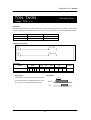
1.1. Overview
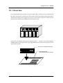
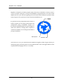
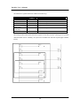
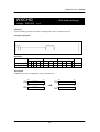
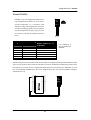
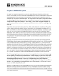
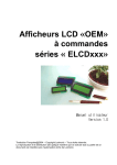
PLC, Programmable Logic Controller, is a typical controller that is commonly used in industrial field.
The picture shown below is general type of PLC which you have been familiar with. Because that its
all-in-one case contains power supply, CPU and I/O, you can place it inside of a control box and
OUTPUT
INPUT
INPUT
CPU
POWER
program various functions by installing extra units where necessary.
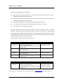
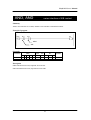
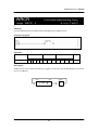
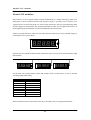
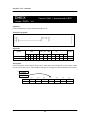
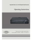
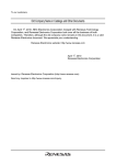
TinyPLC has very different composition from the general PLCs. “TinyPLC” is provided in the forms
of CHIP (similar to CPU of general PLC). By adding additional device such as I/O circuits, users can
organize their own PLC.
52
51
50
49
48
47
46
45
44
43
42
41
40
39
38
37
36
35
34
33
32
31
30
29
28
27
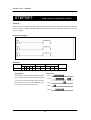
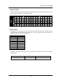
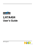
TinyPLC CPU module (TPC-3X series)
1
2
3
4
5
6
7
8
9
10
11
12
13
14
15
16
17
18
19
20
21
22
23
24
25
26
Programmable Logic Controller
3
User-made I/O board
(Or standard I/O board from Comfile)
TinyPLC User’s Manual
TinyPLC gives advantages to user as follows.
l
Being able to design and assemble I/O parts except CPU, users can make their own PLC.
(Suitable for designing dedicated machines)
l
Needing to purchase CPU module only at lower-price than usual PLC, user can reduce the cost
of materials. (profitable to mass-production)
l
User can freely set direction of I/O ports and it makes the most of I/O port.
l
You can reduce cable-wiring work to the minimum, if basic circuits are on PCB.
l
As it is small, you can make compact product.
TinyPLC is suitable for the people who mass-produce FA machine. Originally, TinyPLC is designed
that users compose I/O board and Power Supply. To make easy the process examining and
producing products, Comfile Technology put basic Power Supply Modules and I/O boards (so called
baseboard) as standard type on market. If you use Tiny PLC Module, Baseboard and Power Supply
Module together, it is same as using common PLC.
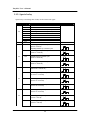
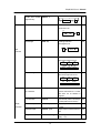
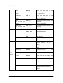
The table below lists Baseboard type and their features.
Model Name
BASE-C20R
(TPC33, 37)
EIO-DI8-24A
EIO-RY8A
EIO-TR8A
Model Name
BASE-C64R
(TPC38)
Description
Basic Baseboard for TPC37
20 points of input and output port
General purpose RS232C connect port LCD, SGN
connection ports
Expansion I/O Module connecting to TPC-BUS
DC24V Input 8 Points
Point of Input and Output
DC24V Input : 12 Points
RELAY Output : 8 Points
Expansion I/O Module connecting to TPC-BUS
REALY Output 8 Points
Expansion I/O Module connecting to TPC-BUS
TR Output 8 Points
Relay Output : 8 Points
Description
Basic Baseboard for TPC38
64 points of input and output port
General purpose RS232C connect port LCD, SGN
connection ports
Point of Input and Output
DC24V Input : 24 Points
RELAY Output : 24 Points
I/O CELL point: 16 Points
DC24V Input : 8 Points
TR Output : 8 Points
*You can find more various baseboard and detailed information at www.comfile.co.kr or Product Catalog, Vo.7.
4
TinyPLC User’s Manual
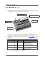
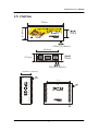
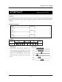
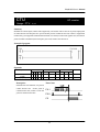
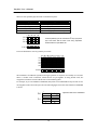
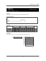
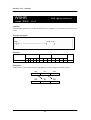
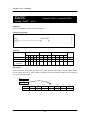
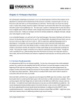
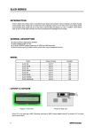
1.2. Baseboard
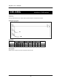
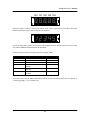
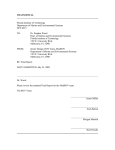
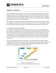
The picture shown below is the diagram of BASE-C20R that is generally used as basic Baseboard of
TinyPLC. You can connect the BASE-C20R to LCD (Serial Display Module provided by Comfile
Technology) and SGN (Seven Segment Network module) directly. There are RS232C connector and
Level converter Circuit for Communication with PC. Basically, there are 8points of built-in Relay
Output and 12points of DC24V Input. Power Supply is available for 5V and 24V (available for
connecting to AU-0524, COMFILE SMPS product).
Serial LCD module
DC24V Input Point
TPC37 Module
DC24V
Power Output
TPC-BUS
AC85V~264V
P2:7
P2:6
P2:5
P2:4
P2:3
P2:2
P2:1
P2:0
P0:3
P0:2
P0:0
Power Input
COMFILE SMPS
P1:0
P1:1
P1:2
P1:3
P1:4
+ - - +
24V 5V
P1:5
Output Status LED
P1:6
RS232C
24V
Input Status LED
P1:7
SGN module
Programmable Logic Controller
High Speed
Counter
Input
+ -
Reserved
Port
P0:1
STATUS LED
DC24V Output Point
AU-0524
You can add Expansion I/O module (Model no. starts with EIO), if necessary, by connecting to TPCBUS.
You can use TPC33 and TPC37 as Tiny PLC Module (CPU).
5
TinyPLC User’s Manual
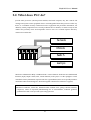
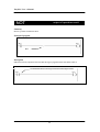
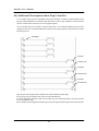
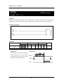
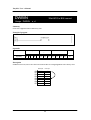
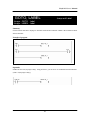
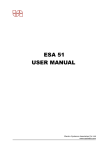
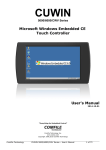
1.3. Block type PLC
Block type PLC consists of CPU module and SMPS (Switching Module Power Supply) Relay Output
and DC24V Input Part. The picture below shows composition of SB36.
RS485 communication module
TinyPLC CPU module: TPC37
DC24V Input
SMPS
supply
Power
Relay Output part
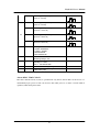
The table shown below is the representative product line of Single-unit PLC. Comfile Technology is
providing more various type of PLC such as Indicator type, Module type and Case type.
You can find more various baseboard and detailed information at www.comfile.co.kr or Product
Catalog, Vo.7
Model
CPU
Power Input
SB-14R
TPC33
AC85V ~ 264V
SB-30S
TPC33
AC85V ~ 264V
SB-22R
TPC33
AC85V ~ 264V
SB-36R
TPC37
AC85V ~ 264V
Input/Output
DC24V input: 8 points RELAY output: 6 points
RS485 communication port
DC24V input: 8 points RELAY output: 6 points
RS485 communication port
EIO extension module connection
DC24V input: 12points RELAY output: 10points
RS485 communication port
DC24V input: 20points RELAY output: 16points
RS485 communication port
Encoder input port
For detailed information on Single-unit PLC, see appendix.
6
TinyPLC User’s Manual
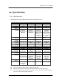
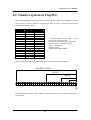
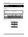
1.4. Specification
1.4.1. TPC3X series
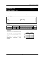
The table below lists comparison about function and capacity of TPC3X series.
Contents
Program memory
Scan-time
Basic Instruction
Application
Instruction
Input/Output Relay
(P area)
DA Output
(DA area)
Internal-relay
(M area)
Step control
(S area)
KEEP Relay
(K area)
Timer (T area)
counter (C area)
Data (D area)
LCD display buffer
(CH area)
SGN display buffer
(G area)
AD converter
( AD area)
High-speed timer
( CNT area)
Package
l
l
l
TPC 26
16K byte
2.5mS
27
84
TPC 33
16K byte
2.5 or 5mS
27
84
TPC 37
128K byte
2.5 or 5mS
27
84
TPC 38
128K byte
5mS
27
84
26 points
(Available for
setting I/O to all of
26 Points)
24 points
(Available for
setting I/O to all
of 26 Points)
-
-
40 points
(Available for
setting I/O to
24points, 8 point is
INPUT only, 8
points is OUTPUT
only)
-
256points
256points
1024points
68 points
(Available for
setting I/O to
24points, 20 point
is INPUT only, 24
points is OUTPUT
only)
10bit,
2chennel
(PWM)
1024points
16 pairs, 255 steps
16 pairs, 255
steps
512 points
32 pairs, 255
steps
512 points
32 pairs, 255
steps
512points
64points(word)
32 points(word)
220 word
20 by 4 (80
byte )
5 by 8 (40 byte )
256points(word)
256 points(word)
1024 word
20 by 4 (80 byte )
256points(word)
256 points(word)
1024 word
20 by 4 (80 byte )
5 by 8 (40 byte )
5 by 8 (40 byte)
8 word
(10bit, 8chennel
built-in A/D)
(Using P2:X as
A/D input)
1 word (16 BIT)
8 word
(10bit, 8chennel
built-in A/D)
(Using P3:X as
A/D input)
1 word (16 BIT)
8 word
(10bit, 8chennel
built-in A/D)
(Using P3:X as
A/D input)
1 word (16 BIT)
36 pins DIP type
52pins DIP type
80 pins DIP type
512 points
64 points(word)
32 points(word)
220 word
20 by 4 (80 byte)
5 by 8 (40 byte )
8 word
(10bit, 8chennel
built-in A/D) (Using
P2:X as A/D input)
1 word (16 BIT)
40pins DIP type
(semiconductor
chip)
TPC3X series is TPC26, TPC33, TPC37 and TPC38. (Jan 2003)
SGN is Product name of Seven Segment Display Module from Comfile Technology.
In case of connection with LCD, only Serial LCD module provided from Comfile Technology is
allowed to connect toTPC3X (1line connection)
7
TinyPLC User’s Manual
1.4.2. TinyPLC
The table below describes general specifications of Tiny PLC.
Item
SMPS Power Source Input
Tiny PLC Power Source
Power Consumption
Power Failure Allowance
Operation Temperature
Storage Temperature
Working Humidity
Working Condition
Noise Area
Pressure-proof
Insulation Resistance
Vibration-proof
Impact
Ground
Specification
AC 85V~254V 50~60Hz (in case apply AU-0524)
DC 5V Single Power Source
10VA
10mS
0~55 ℃
-10 ~ 70 ℃
5 ~95% RH, no dew form
no dust and gas
1500V Vpp, 1uS
AC 1500V / min
Over 10M ohm (DC 500V insulation resistance)
16.7Hz complex vibration 2mm, 2 hr
10 G (3 shock each in 3 axes)
100 Ohm
8
TinyPLC User’s Manual
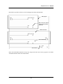
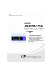
1.5. Outline
31.8mm
72mm
900mil
100mil (2.54mm)
46.2mm
20.7mm
700mil
100mil (2.54mm)
600mil(15.24mm)
1
2
3
4
5
6
7
8
9
10
11
12
13
14
15
16
17
18
19
20
40
39
38
37
36
35
34
33
32
31
30
29
28
27
26
25
24
23
22
21
2.54mm
1900 mil
1
2
3
4
5
6
7
8
9
10
11
12
13
14
15
16
17
18
19
20
41
42
43
44
45
46
47
48
49
50
51
52
53
54
55
56
57
58
59
60
40
39
38
37
36
35
34
33
32
31
30
29
28
27
26
25
24
23
22
21
80
79
78
77
76
75
74
73
72
71
70
69
68
67
66
65
64
63
62
61
2mm
9
2mm
TinyPLC User’s Manual
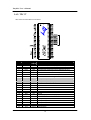
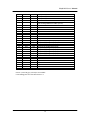
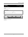
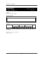
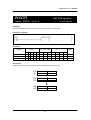
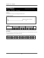
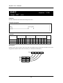
1.6. PINOUT
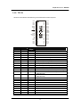
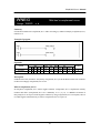
1.6.1. TPC33
This section describes PIN OUT of TPC33.
Pin no.
name
1
2
3
4
5
6
7
8
9
10
11
12
13
14
15
16
17
18
19
20
+5V
GND
DRX
DTX
RX
TX
485TE
CLK
Dout
Din
P0:0
P0:1
P0:2
P0:3
P0:4
P0:5
P0:6
P0:7
P1:7
P1:6
Input
/Output*
Power
Power
Input
Output
Input
Output
Output
Output
Output
Input
I/O
I/O
I/O
I/O
I/O
I/O
I/O
I/O
I/O
I/O
21
22
P1:5
P1:4
I/O
I/O
Description
Power Source Input Terminal ( Support 4.5V~5.5V)
Ground
RX Terminal for download (Connect to RS232C-TD of PC)
TX Terminal for download (Connect to RS232C-RD of PC)
Common communication terminal RX (Connect to TD of Host)
Common communication terminal TX (Connect to RD of Host)
RS485 transmission enable signal
For expansion (Clock signal)
For expansion (Data Output signal)
For expansion (Data Input signal)
I/O port
I/O port (High-speed counter input port)
I/O port
I/O port
I/O port
I/O port
I/O port
I/O port
I/O port
I/O port
I/O port
I/O port
10
TinyPLC User’s Manual
23
24
25
P1:3
P1:2
P1:1
I/O
I/O
I/O
26
27
28
29
30
31
32
33
34
35
36
P1:0
P2:7
P2:6
P2:5
P2:4
P2:3
P2:2
P2:1
P2:0
Vref
N/C
I/O
I/O
I/O
I/O
I/O
I/O
I/O
I/O
I/O
I
I/O port
I/O port
I/O port
I/O port
I/O port (Analog Ch7 Input port)
I/O port (Analog Ch6 Input port)
I/O port (Analog Ch5 Input port)
I/O port (Analog Ch4 Input port)
I/O port (Analog Ch3 Input port)
I/O port (Analog Ch2 Input port)
I/O port (Analog Ch1 Input port)
I/O port (Analog Ch0 Input port)
Analog standard voltage Input
Not connected
* Pin no. 8, 9 and10 (grey-colored) is not available.
* On installing, take care of location of Pin no. 1.
11
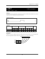
TinyPLC User’s Manual
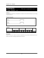
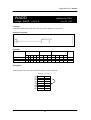
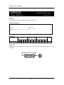
1.6.2. TPC 37
This section describes PIN OUT of TPC37.
Input
Pin no.
name
1
2
3
4
5
6
7
8
9
10
11
12
13
14
15
16
17
18
19
20
21
22
23
+5V
GND
DRX
DTX
RX
TX
485TE
CLK
Dout
Din
P0:0
P0:1
P0:2
P0:3
P0:4
P0:5
P0:6
P0:7
P1:0
P1:1
P1:2
P1:3
P1:4
Input/
Output*
Power
Power
Input
Output
Input
Output
Output
Output
Output
Input
I/O
I/O
I/O
I/O
I/O
I/O
I/O
I/O
Output
Output
Output
Output
Output
Function
Power Source Input Terminal ( Support 4.5V~5.5V)
Ground
RX Terminal for download (Connect to RS232C-TD of PC)
TX Terminal for download (Connect to RS232C-RD of PC)
Common communication terminal RX (Connect to TD of Host)
Common communication terminal TX (Connect to RD of Host)
RS485 transmission enable signal
For expansion (Clock signal)
For expansion (Data Output signal)
For expansion (Data Input signal)
I/O port
I/O port
I/O port
I/O port
I/O port
I/O port
I/O port (High-speed counter Input port)
I/O port
Output port only
Output port only
Output port only
Output port only
Output port only
12
TinyPLC User’s Manual
24
25
26
27
28
P1:5
P1:6
P1:7
GND
VREF
Output
Output
Output
Power
Input
29
30
31
32
33
34
35
36
37
38
39
40
41
42
43
44
45
46
47
48
49
50
51
52
P2:7
P2:6
P2:5
P2:4
P2:3
P2:2
P2:1
P2:0
P3:7
P3:6
P3:5
P3:4
P3:3
P3:2
P3:1
P3:0
P4:7
P4:6
P4:5
P4:4
P4:3
P4:2
P4:1
P4:0
I/O
I/O
I/O
I/O
I/O
I/O
I/O
I/O
Input
Input
Input
Input
Input
Input
Input
Input
I/O
I/O
I/O
I/O
I/O
I/O
I/O
I/O
Output port only
Output port only
Output port only
Ground terminal
A/D standard voltage Input
(AD converting between 0V~VREF. Up to 5V)
I/O port
I/O port
I/O port
I/O port
I/O port
I/O port
I/O port
I/O port
Input port only (Analog Ch7 Input port)
Input port only (Analog Ch6 Input port)
Input port only (Analog Ch5 Input port)
Input port only (Analog Ch4 Input port)
Input port only (Analog Ch3 Input port)
Input port only (Analog Ch2 Input port)
Input port only (Analog Ch1 Input port)
Input port only (Analog Ch0 Input port)
I/O port
I/O port
I/O port
I/O port
I/O port
I/O port
I/O port
I/O port
* Pin no. 8, 9 and 10 (grey-colored) is not available.
* On installing, take care of location of Pin no. 1.
13
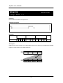
TinyPLC User’s Manual
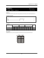
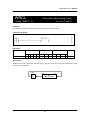
1.6.3. TPC 38
This section describes PIN OUT of TPC38.
Pin no.
Name
1
2
3
4
5
6
7
8
+5V
GND
DRX
DTX
RX
TX
485TE
VREF
Input/
Output*
Power
Power
Input
Output
Input
Output
Output
Input
9
10
11
12
13
14
15
16
17
18
19
20
21
22
23
24
25
P0:0
P0:1
P0:2
P0:3
P1:0
P1:1
P1:2
P1:3
P1:4
P1:5
P1:6
P1:7
P2:7
P2:6
P2:5
P2:4
P2:3
I/O
I/O
I/O
I/O
Output
Output
Output
Output
Output
Output
Output
Output
I/O
I/O
I/O
I/O
I/O
Function
Power Source Input Terminal ( Support 4.5V~5.5V)
Ground
RX Terminal for download (Connect to RS232C-TD of PC)
TX Terminal for download (Connect to RS232C-RD of PC)
Common communication terminal RX (Connect to TD of Host)
Common communication terminal TX (Connect to RD of Host)
RS485 transmission enable signal
A/D standard voltage Input
(AD converting between 0V~VREF Up to 5V)
I/O port
I/O port
I/O port
I/O port
Output port only
Output port only
Output port only
Output port only
Output port only
Output port only
Output port only
Output port only
I/O port
I/O port
I/O port
I/O port
I/O port
14
TinyPLC User’s Manual
26
27
28
29
30
31
32
33
34
35
36
37
38
39
40
41
42
43
44
45
46
47
48
49
50
51
52
53
54
55
56
57
58
59
60
61
62
63
64
65
66
67
68
69
70
71
72
73
74
75
P2:2
P2:1
P2:0
P0:7
P0:6
P0:5
P0:4
P5:7
P5:6
P5:5
P5:4
P5:3
P5:2
P5:1
P5:0
+5V
GND
DA0
DA1
P7:0
P7:1
P7:2
P7:3
P7:4
P7:5
P7:6
P7:7
P4:0
P4:1
P4:2
P4:3
P4:4
P4:5
P4:6
P4:7
P3:7
P3:6
P3:5
P3:4
P3:3
P3:2
P3:1
P3:0
P6:7
P6:6
P6:5
P6:4
P6:3
P6:2
P6:1
I/O
I/O
I/O
I/O
I/O
I/O
I/O
Output
Output
Output
Output
Output
Output
Output
Output
Power
Power
Output
Output
Input
Input
Input
Input
Input
Input
Input
Input
I/O
I/O
I/O
I/O
I/O
I/O
I/O
I/O
Input
Input
Input
Input
Input
Input
Input
Input
Output
Output
Output
Output
Output
Output
Output
I/O port
I/O port
I/O port
I/O port
I/O port (High-speed counter Input port)
I/O port
I/O port
Output port only
Output port only
Output port only
Output port only
Output port only
Output port only
Output port only
Output port only
Power Source Input Terminal ( Support 4.5V~5.5V)
Ground
DA Output port only 0 (PWM Output state)
DA Output port only 1 (PWM Output state)
Input port only
Input port only
Input port only
Input port only
Input port only
Input port only
Input port only
Input port only
I/O port
I/O port
I/O port
I/O port
I/O port
I/O port
I/O port
I/O port
Input port only (Analog Ch7 Input port)
Input port only (Analog Ch6 Input port)
Input port only (Analog Ch5 Input port)
Input port only (Analog Ch4 Input port)
Input port only (Analog Ch3 Input port)
Input port only (Analog Ch2 Input port)
Input port only (Analog Ch1 Input port)
Input port only (Analog Ch0 Input port)
Output port only
Output port only
Output port only
Output port only
Output port only
Output port only
Output port only
15
TinyPLC User’s Manual
76
77
78
79
80
P6:0
P8:3
P8:2
P8:1
P8:0
Output
Input
Input
Input
Input
Output port only
Input port only
Input port only
Input port only
Input port only
* On installing, make certain location of Pin no. 1.
Ports of TPC38 are digested as follows;
I/O port: 24points
… … … … … … … … (P0, P2, P4)
Input port only: 20points
Output port only: 24points
… … … … … (P3, P7, P8)
… … … … (P1, P5, P6)
DA Output port: 2points
Total: 70points
Caution
The following instruction is prohibited from using at P5~P8 of TPC38.
LCDOUT, SGNOUT, THIN, KEYSCAN
16
TinyPLC User’s Manual
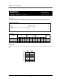
1.6.4. TPC26
TPC26 is semiconductor and Module type PLC different from other TinyPLCs.
P0:0
P0:1
P0:2
P0:3
485TE
DOUT
DIN
CLK
RESET
+5V
GND
OSCOUT
OSCIN
RX
TX
P3:0
P3:1
P0:4
P0:5
P0:6
Pin no.
Name
1
2
3
4
5
6
7
8
9
10
11
12
13
14
P0:0
P0:1
P0:2
P0:3
485TE
DOUT
DIN
CLK
/RESET
+5V
GND
OSCOUT
OSCIN
RX
Input/
Output*
I/O
I/O
I/O
I/O
Output
Output
Input
Output
Input
Power
Power
Output
Input
Input
15
TX
Output
16
17
18
19
20
21
22
23
24
25
26
P3:0
P3:1
P0:4
P0:5
P0:6
P0:7
P1:0
P1:1
P1:2
P1:3
P1:4
I/O
I/O
I/O
I/O
I/O
I/O
I/O
I/O
I/O
I/O
I/O
1
2
3
4
5
6
7
8
9
10
11
12
13
14
15
16
17
18
19
20
40
39
38
37
36
35
34
33
32
31
30
29
28
27
26
25
24
23
22
21
P2:0
P2:1
P2:2
P2:3
P2:4
P2:5
P2:6
P2:7
AREF
AGND
AVCC
P1:7
P1:6
P1:5
P1:4
P1:3
P1:2
P1:1
P1:0
P0:7
Function
I/O port
I/O port (High-speed counter Input port)
I/O port
I/O port
RS485 transmission enable signal
For expansion (DATA OUTPUT) signal
For expansion (DATA INPUT) signal
For expansion (CLOCK) signal
Reset signal (Reset will turn on at Low status)
Power source Input terminal (Support 4.5V~5.5V)
Ground terminal
Oscillator connect terminal
Oscillator connect terminal (7.3728MHz Crystal connecting)
Download and RS232/485 communication port
(19200 baud rate)
Download and RS232/485 communication port
(19200 baud rate)
I/O port
I/O port
I/O port
I/O port
I/O port
I/O port
I/O port
I/O port
I/O port
I/O port
I/O port
17
TinyPLC User’s Manual
l
27
28
29
30
31
32
P1:5
P1:6
P1:7
AVCC
AGND
AREF
I/O
I/O
I/O
Power
Power
Input
33
34
35
36
37
38
39
40
P2:7
P2:6
P2:5
P2:4
P2:3
P2:2
P2:1
P2:0
I/O
I/O
I/O
I/O
I/O
I/O
I/O
I/O
I/O port
I/O port
I/O port
Analog Power source Input terminal
Analog Ground Input terminal
Analog Input Standard voltage Input terminal
Convert 0~3V, if input is 3V. Convert 0~5V, if input is 5V.
Input port only (Analog Ch7 Input port)
Input port only (Analog Ch6 Input port)
Input port only (Analog Ch5 Input port)
Input port only (Analog Ch4 Input port)
Input port only (Analog Ch3 Input port)
Input port only (Analog Ch2 Input port)
Input port only (Analog Ch1 Input port)
Input port only (Analog Ch0 Input port)
All pins name of which start with P are I/O pins. The name of all I/O pins starts with P. It can
be used as Input or Output pin alternatively in accordance with User’s definition.
l
Because CLKIN terminal can detect Rising Edge, High-speed pulse even about 20 KHz can be
counted.
l
OSCIN, OSCOUT must be connected to 7.3728MHz Crystal.
l
RESET terminal should be connected to 5V Power source without any additional circuit.
CAUTION
l
Reading and erasing TPC26 chip with a general ROM-writer could bring about critical adverse
effect or disability. We strongly recommend you do not to perform that.
l
TPC26, which is provided in form of chip, is very vulnerable to static electricity.
l
It is strongly recommended to install Bypass condenser (around 0.1uF) at the closest part of
power supply (+5V, GND). Bypass condenser is an essential component ensuring stable
operation of the chip. (Ceramic or monolithic type condenser)
l
Data communication of TPC26 is 19200 baud rate. (Other TPC 3X is 9600 baud rate).
18
TinyPLC User’s Manual
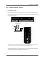
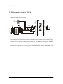
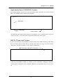
1.7. Connection with PC
1.7.1. RS232C cable
DRX and DTX, allocated at pin no. 3 and 4 of TPC33/37/38 each, are communication port for use of
download and monitoring. There is no need of extra converting device in connecting with RD and TD
terminal in RS232C port of PC.
TinyPLC
RS232C of PC
(9 pins)
5 (GND)
3 (TD)
2 ( RD)
2 (GND)
3 (DRX)
4 (DTX)
RS232C of PC
(25pins)
7 (GND)
2 (TD)
3 (RD)
PC RS232 (9 PIN)
RD
TD
GND
1
2
3
4
5
6
7
8
9
1
2
3
4
5
6
7
8
9
10
11
12
13
14
15
16
17
18
19
20
21
22
23
24
25
26
Programmable Logic Controller
+5V
GND
DRX
DTX
RX
TX
SS
CLK
DOUT
DIN
P0:0
P0:1
P0:2
P0:3
P0:4
P0:5
P0:6
P0:7
P1:0
P1:1
P1:2
P1:3
P1:4
P1:5
P1:6
P1:7
52
51
50
49
48
47
46
45
44
43
42
41
40
39
38
37
36
35
34
33
32
31
30
29
28
27
P4:0
P4:1
P4:2
P4:3
P4:4
P4:5
P4:6
P4:7
P3:0
P3:1
P3:2
P3:3
P3:4
P3:5
P3:6
P3:7
P2:0
P2:1
P2:2
P2:3
P2:4
P2:5
P2:6
P2:7
VREF
GND
Communication protocol is RS232C, 19200 baud rate, N,8,1. As TPC module has built-in Level
convert circuit, download ports (pin no.3 and 4) can be connected to RS232C directly.
* Caution: Maximum length of download cable can not be more than 2M and the cable must be
separated in operation. (To avoid affixing of unnecessary noise)
19
TinyPLC User’s Manual
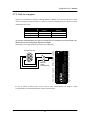
1.7.2. Download circuit for TPC26
Communication of TPC26 to PC is different from that of other modules. The picture shown below is
simplest circuit for operating TPC26.
2
PC
RS232C
Port
3
5
5V
5V
0.1uF
5V
0.1uF
0.1uF
0.1uF
0.1uF
1
2
3
4
5
6
7
8
0.1uF
16
15
14
13
12
11
10
9
7.3728
MHz
X-TAL
P0:0
P0:1
P0:2
P0:3
485TE
DOUT
DIN
CLK
RESET
+5V
GND
OSCOUT
OSCIN
RX
TX
P3:0
P3:1
P0:4
P0:5
P0:6
1
2
3
4
5
6
7
8
9
10
11
12
13
14
15
16
17
18
19
20
40
39
38
37
36
35
34
33
32
31
30
29
28
27
26
25
24
23
22
21
P2:0
P2:1
P2:2
P2:3
P2:4
P2:5
P2:6
P2:7
AREF
AGND
AVCC
P1:7
P1:6
P1:5
P1:4
P1:3
P1:2
P1:1
P1:0
P0:7
5V
5V
Level converting chip, MAX232, is used to communicate with RS232C in PC. (As most of Single-unit
PLC and baseboard have a circuit which has same function as shown above circuit, users have only to
connect cable for instant use.) Being semiconductor type, TPC26 should be connected with basic
circuits such as Oscillator circuit, Power-supply circuit and Reset circuit in order to operate.
Having same composition as above circuit, basic dedicated baseboard of TPC26, BASE-F24R, would
be used with ease.
20
TinyPLC User’s Manual
1.7.3. Link to computer
TinyPLC can be linked to computer. Through RS232 (or RS485), user can read and write in data
memory of TinyPLC. RX and TX, pin no. 5 and 6, are common communication ports (protocol is fixed
at 9600 baud rate, N, 8, 1).
TinyPLC pin
2 (GND)
5 (RX)
6 (TX)
RS232C of PC
(9 pins)
5 (GND)
3 (TD)
2 ( RD)
RS232C of PC
(25 pins)
7 (GND)
2 (TD)
3 (RD)
As common communication port (pin no.5 and 6) have not built-in level convert circuit, user
MUST use level converting chip to input 5V level signal.
(Baseboard from Comfile Technology includes converting chip)
PC RS232 (9 PIN)
1
2
3
4
5
6
7
8
9
1
2
3
4
5
6
7
8
9
10
11
12
13
14
15
16
17
18
19
20
21
22
23
24
25
26
Programmable Logic Controller
MAX232
LEVEL
CONVERTER
+5V
GND
DRX
DTX
RX
TX
SS
CLK
DOUT
DIN
P0:0
P0:1
P0:2
P0:3
P0:4
P0:5
P0:6
P0:7
P1:0
P1:1
P1:2
P1:3
P1:4
P1:5
P1:6
P1:7
52
51
50
49
48
47
46
45
44
43
42
41
40
39
38
37
36
35
34
33
32
31
30
29
28
27
P4:0
P4:1
P4:2
P4:3
P4:4
P4:5
P4:6
P4:7
P3:0
P3:1
P3:2
P3:3
P3:4
P3:5
P3:6
P3:7
P2:0
P2:1
P2:2
P2:3
P2:4
P2:5
P2:6
P2:7
VREF
GND
In case of TPC26, download port can be used for data communication. See chapter 6 Data
Communication for detailed information on data communication.
21
TinyPLC User’s Manual
1.8. Data memory map
1.8.1. TPC33
7
P0
Byte area
~
0
P
Basic I/O
(24points)
P2
P3
7
F0
Byte area
~
0
F
Special relay
(64points)
Word area
15
~
0
T0
F7
M0
Remote I/O
(or internal relay)
(1024points)
T
Timer area
KEEP area(T16~31)
M
Internal relay
(256points)
TPC33 (up to T63)
TPC33 (up to T31)
C0
P15
C
Counter area
(total 32points)
M31
Total 28points
C16
S0
S
Step controller
(16pairs)
S15 0 ~ 255steps
K0
K
KEEP relay
(512points)
K63 7
~
0
KEEP area
C31
D0
D
Data area
(220words)
D219
CH0
CH area (80bytes)
LCD buffer
G0
AD0
AD7
10bit A/D converting
Result storage area
G area (40bytes)
SGN buffer
CNT 16bit high-speed counter
value area
n
n
n
n
n
As being in keep area, some part of Timer/Counter area is able to conserve data even while power is
off.
Timer/Counter area is unitized as 16bit (1 word) unit, the others (P, M, K, CH, G) is unitized as byte
unit.
Word unit area is stored data with following high/low rank byte order. (High rank byte enter low
address)
Except Keep area, all area turn “0” when power-on.
As data in Keep area is written in EEPROM physically, there is no need of extra battery backup.
22
TinyPLC User’s Manual
1.8.2. TPC37, 38
7
P0
Byte area
~
0
P
Basic I/O
(40points)
P4
P5
7
F0
Byte area
~
0
Word area
15
~
0
F
Special relay
(128points)
T0
M
Internal relay
(1024points)
T239
T240
T
Timer area
(total 256points)
F15
M0
Remote I/O
(or internal relay)
(88points)
KEEP area
T255
C0
P15
M127
Total 128points
C
Counter area
(Total 256points)
S0
S
Step controller
(32pairs)
S31 0 ~ 255 steps
K0
K
KEEP relay
(256points)
K31 0
~
7
C239
C240
KEEP area
C255
D0
D
Data area
(1024 words)
CH0
CH area (80bytes)
LCD buffer
D102
3
G0
G area( (40bytes)
SGN buffer
AD0
AD7
10bit A/D converting
Result storage area
CNT
16bit high-speed counter
value area
DA0 10bit D/A converting value
DA1
Storage area
(TPC38 only)
23
TinyPLC User’s Manual
1.8.3. TPC26
7
P0
Byte area
~
0
P
Basic Input/Output
(24points)
P2
P3
7
F0
Byte area
~
0
F
Special Relay
(64 points)
Word area
15
~
0
T0
F7
M0
Remote I/O
(or Internal-relay)
(104 points)
P15
T
Timer area
Keep area (T16~31)
M
Additional relay
(256 points)
T63
C0
C
Counter area
(total 32 points)
M31
Total 128 points
C16
S0
S
Step controller
(16 pairs)
S15 0 ~ 255 steps
K0
K
KEEP relay
(512 points)
K63 7
~
0
KEEP area
C31
D0
D
Data area
(220 words)
D219
CH0
CH area
(80
bytes)
LCD buffer
G0
AD0
AD7
10 bit A/D converting
Result storage area
CNT
16bit high-speed area
G area (40bytes)
SGN buffer
n
n
n
n
n
As being in keep area, some part of Timer/Counter area is able to conserve data even while power is
off.
Timer/Counter area is unitized as 16bit (1 word) unit, the others (P, M, K, CH, G) is unitized as byte
unit.
Word unit area is stored data with following high/low rank byte order. (High rank byte enter low
address)
Except Keep area, all area turn “0” when power-on.
As data in Keep area is written in EEPROM physically, there is no need of extra battery backup.
24
TinyPLC User’s Manual
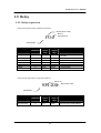
1.9. Relay
1.9.1. Relay expression
All relay of TinyPLC can be symbolized as follows;
Word or byte (0~ 1023)
Bit (0~7)
Not more than 8
P0:0
Relay identifier
Relay type
Relay
identification
I/O relay
P
Word
express
range
0~15
Special relay
Internal relay
Keep relay
Timer
Counter
Data
F
M
K
T
C
D
0~15
0~127
0~31
0~255
0~255
0~1023
Bit
express
range
0~7
0~7
0~7
0~7
Not use
Not use
Not use
Function
Turn ON/OFF outer ports, read
pins state.
Keep state while power off
Timer terminal
Counter terminal
Data area
S relay used in step control is expressed as follows;
Pair (0~ 31)
Step number: 0~255
S31:200
Step identifier
Relay type
Step control relay
Relay
identification
S
Word
express
range
0~31
Bit
express
range
0~255
25
Function
Step control (up to 32pair 256step)
TinyPLC User’s Manual
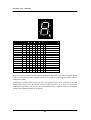
1.9.2. Special relay
Special relay is controlling state of CPU, mode selection and signal.
Special relay
F0:0
F0:1
F0:2
F0
F0:3
F0:4
F0:5
F0:6
F0:7
F1:7
F1
F2:0
F2
F3
F4
Function
Constant OFF
Constant ON
ON during 1 scan time at initial power input
OFF during 1 scan time at initial power input
Not use
Generating pulse by 0.01sec cycle
(5mS on : 5mS off)
Repeating ON/OFF by 1 scan time cycle
Remarks
0.01s
F2:1
Generating pulse by 0.02sec cycle
(10mS on : 10mS off)
0.02s
F2:2
Generating pulse by 0.04sec cycle
(20mS on : 20mS off)
0.04s
F2:3
Generating pulse by 0.08sec cycle
(40mS on : 40mS off)
0.08s
F3:0
Generating pulse by 0.1sec cycle
(0.05 sec on : 0.05 sec off)
0.1s
F3:1
Generating pulse by 0.2sec cycle
(0.1 sec on : 0.1 sec off)
0.2s
F3:2
Generating pulse by 0.4sec cycle
(0.2 sec on : 0.2 sec off)
F3:3
Generating pulse by 0.8sec cycle
(0.4 sec on : 0.4 sec off)
F4:0
Generating pulse by 1sec cycle
(0.5 sec on : 0.5 sec off)
1s
F4:1
Generating pulse by 2sec cycle
(1sec on : 1sec off)
2s
F4:2
Generating pulse by 4sec cycle
(2 sec on : 2 sec off)
4s
26
0.4s
0.8s
TinyPLC User’s Manual
F5
F6
F7
F8
F9
F10
F4:3
Generating pulse by 8sec cycle
(4 sec on : 4 sec off)
F5:0
Generating pulse by 10sec cycle
(5 sec on : 5 sec off)
10s
F5:1
Generating pulse by 20sec cycle
(10 sec on : 10 sec off)
20s
F5:2
Generating pulse by 40sec cycle
(20 sec on : 20 sec off)
40s
F5:3
Generating pulse by 80sec cycle
(40 sec on : 40 sec off)
80s
Selecting Korean font for Korean LCD
0 : SMALL SAEMMOOL
1 : SMALL GOTHIC
2 : BIG MYUNGJO
3 : BIG TAEGOTHIC
Address for RS485 communication
Allowed appointing 0~ 255
Real time sec-clock
Operating in 0 ~ 59sec
F8:0 ? 1sec ON/1sec OFF
8s
For WRITE
TPC33
Real time minute-clock (operating 0~ 59minutes)
N/A in TPC33
Real time hour-clock (operating 0~255hour, return to N/A in TPC33
0 after reaching 255)
About REAL TIME CLOCK
RTC that is allocated at F8, F9, F10, is operational in only TPC37, TPC38. RTC can be clear to “0”
automatically upon power-on and can conserve data while power is on. RTC is much useful in
operation, which need precise timer.
27
TinyPLC User’s Manual
Chapter 2
Basic of PLC
This chapter gives you general idea of PLC and ladder
programming. If you have ever used PLC, you do not
have to read this chapter.
28
TinyPLC User’s Manual
2.1. What is PLC?
PLC (Programmable Logic Controller), which is one of the most typical FA controllers, has wide range
of users and is on the right track as industrial controllers. As being comprehensible diagram
programming language, Relay Ladder Diagram is providing ease approach to engineers, who have
not majored in electronics/computer science, and is applicable in short time without accumulated
experience in industrial field. PLC is a controller that is programmed and operated by Relay Ladder
Diagram.
<Example: Relay Ladder Diagram>
The most outstanding difference of Relay Ladder Diagram from general programming language such
as C, Assembly and BASIC is “Multi-tasking”.(Multi-tasking: conducting more than 2 operations
simultaneously) C and Assembly are sequential programming language. It means that only one
operation can be processed at a certain point of time in processing.
But, it is a problem in PLC programming due that Ladder Diagram supports multi-tasking. Diagram
shown below describes a structure that X is on if A inputs and Y is on if B inputs at the same time.
A
X
B
Y
Two circuits work independently
without interference.
29
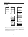
TinyPLC User’s Manual
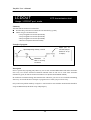
Regardless of complicacy of Ladder program, input points/relays on the ladder are always ready to
work in accordance with input. A concept of SCANTIME in programming PLC is from this. SCAN
TIME means time space between beginning and end of Relay Ladder Program in operation. Relay
Ladder Program runs repeatedly at certain constant SCANTIME interval.
Running
program
It is performed not only interpretation and execution of
Ladder program but also Input/output-refresh and
self-inspection during SCANTIME. TinyPLC has
fixed-5mS SCANTIME regardless program length. It is
much more efficient to manage time compared to
variable SCANTIME. (You can change SCAN TIME as
per types of machine.)
Self-inspection
I/O Refresh
You don’t have to worry too much about SCAN TIME in using Relay Ladder Program, but keep in
mind that program is basically placed on SCAN TIME structure. This is the biggest difference from
sequential technical language such as C or Assembly.
30
TinyPLC User’s Manual
2.2. What does PLC do?
Just like other processors (One-chip microcontroller, One-board computer, PC), PLC controls and
manages and operate various peripheral devices. It is distinguished from other processors in the way
that it, as a substitute of Relay switchboard used in equipment and production automation, can
effectively control peripheral devices on each production line. For instance, it controls conveyers and
enables each proximity sensor and temperature sensor to move in a constant sequence after they
contact valves and motors.
Sensors
Motors
Switch
Lamps
While PLC substituted for Relay switchboard had a various functions beside the most fundamental
functions (input/output control, timer, counter function) in the past, it is in the spotlight as a total
controller for factory automation at present. PLC has a great influence, thus no one possibly mentions
automation without considering PLC. The following table summarizes to what PLC is applied;
Automated warehouse, return line, industrial Robot, machine tools, pumps, thermal controller,
compressor, loader in inspection/manufacturing line of semiconductor, industrial generator,
production line such as conveyer and reprocessing system etc.
31
TinyPLC User’s Manual
2.3. General structure of PLC
PLC consists of three fundamental structures;
CPU, which play a role in human’s brain, reads nimonic type of data/instruction from the memory
then interprets and runs it. I/O part accept external input and proceed output as if human’s eyes, ears,
hands and legs. Memory part is in charge of memorization and stores all the information incurred
during operation and ladder program drawn by user.
There are several types of memory; RAM, ROM, EEPROM, FLASH ROM etc.
l
RAM (Random Access Memory) can freely read and write.
l
ROM (Read Only Memory) can only read.
l
EEPROM can be clear electrically and be changed its contents during running and stays online
without electric power. Otherwise, RAM can not conserve its contents without electric power.
l
FLASH ROM has a similar feature as EEPROM in the way of running but is different from
EEPROM in the way of manufacturing.
Ladder Diagram drawn by user is translated into performable codes and stored in FLASH ROM. All
information incurred during operation is stored in RAM. Some information needed to be conserved
after power-off is stored separately in EEPROM (KEEP area).
I/O part of TinyPLC is composed of I/O port with the TTL level format (*TTL level recognizes 0V as 0
and 5V as 1). Therefore, you can turn ON/OFF a great amount of load by adding Relay or Photo
coupler at I/O ports. COMFILE supplies this I/O extension part as a product named BASEBOARD.
32
TinyPLC User’s Manual
2.4. Type of Relay
Relays in PLC mean not only components connecting outer-part but also internal relays not providing
external output. The followings are descriptions for Relays dealt with on TinyPLC. Since Relays are
classified with alphabet initial as P, M, K, T, C, you also had better learn them.
Initial
Name
Functions
P
Input/output
This Relay is directly connected to external Relays or input parts. An input
Relay
contact point relays the HIGH/LOW state or an external input port. An
output contact point is connected to external valve or motor and influence
their states when input relay changes.
There are totally 128 points of P area on TinyPLC including spares.
Some part of P area is used for connection with external I/O. The other
part is used as REMOTE I/O etc. If REMOTE I/O is not used, it could be
used as an Internal Relay.
M
Internal Relay
This Relay operates only within program. It can not execute input /output
directly outside, but play a supporting role in transmitting information etc
(M area is only place where can be used for input of DF, DFN.).
K
Keep Relay
This Relay has a same role as M relay, but is different in conserving its
data without electric power. Data needed to keep during power failure is
to be stored here.
F
Special Relay
This Relay displays state of internal operation, result of operation and
various information of time in PLC. For instance, some relay repeat
ON/OFF every one second.
T
Timer
This Relay controls time. It has ON timer and OFF timer, and computes
time in 10mS or 100mS unit and its contacting point is ON when it
reaches a settled number. Please refer to instruction for details.
33
TinyPLC User’s Manual
C
Counter
This Relay counts the number of pulse. It has Up timer and Down timer,
counts the edge part of input pulse. Its contact point turns on when it
reaches a settled number. Please refer to Chapter 3 instruction for
details (Pulses faster than SCAN TIME should be measured by highspeed counter.).
D
Data
This Relay stores data used for operation and deals with data in word
(16bit) unit. There are several instructions on TinyPLC, which deal with
Data.
S
Step Controller
This Relay is specially used for sequential works. Since PLC runs
Relay
repeatedly during SCAN TIME, sequential works, which can be solved
quite simply by other program languages, can be difficult to work
sometimes. In this case, you can solve the problem easily by using Step
Controller Relay.
CH
LCD Display
This is for display buffer of LCD. ASCII code date written in CH area will
appear on LCD. When the CH area is full with blank (ASCII code 20H),
LCD is cleared.
G
SGN Display
This is for buffer of seven-segment display. ASCII code written in G area
will appear on SGN (Seven-seGment compile Module).
AD
AD Conversion
The result of A/D conversion is recorded in AD area. TinyPLC do A/D
result storage
converting automatically without user’s instruction and the result is
recorded in AD area. Users can get A/D results simply by referring to this
area.
CNT
High-speed
The result of high-speed counter is recorded in CNT area. Without any
counter result
instruction, users can use the result of high-speed counter simply by
storage
referring to CNT area.
* All S areas except KEEP area is reset to 0 on power-on.
34
TinyPLC User’s Manual
2.5. Ladder INPUT and RUN
In order to use PLC, you need a Ladder Program input device, download cable (RS232C cable) and
PLC mail frame.
There are many Ladder input devices and some of them use Handy Loader. However, PC is most
common device these days. Because Ladder can be described with graphics on PC and that data
backup is relatively easy. Ladder diagrams drawn on PC can be downloaded or uploaded through
RS232C cable. Downloaded programs are ready to operate in the Stand-Alone state and input
programs run whenever power is turned on because they are always saved even after power is off.
Compile and
Download
Ladder Drawing
Operation
Checking
Development of program with TinyPLC proceeds repeating three steps, which are Ladder drawing,
Compile/download and Operation checking.
35
TinyPLC User’s Manual
Program translation process on TinyPLC
TinyPLC take three steps of translation process in order to download Ladder program. Since TinyPLC
is a compile-typed PLC, drawn Ladders are translated into nimonics and then changed into assembler
codes by compiling (MPGL2 program operates automatically by this point, users don’t have to worry
about it.). Then, Ladders are downloaded into Tiny PLC module through RS232C cable.
Ladder
Command
LOAD
OR
OUT
END
P1:0
P1:1
P1:2
36
Machine Code
34
98
23
89
FA
9B
43
36
00
03
11
00
37
C9
32
00
TinyPLC User’s Manual
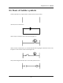
2.6. Basic of Ladder symbols
Ladder symbol has very simple structure. Ladder needs two basic bus lines.
These bus lines are electric lines.
When a lamp is connected to those electric lines, the light is on.
When a switch is connected here, it is described like the following diagram. When the switch is ON,
the light is on and when the switch is OFF, the light is off.
Relay Ladder Diagram describes above circuit with symbols as below.
37
TinyPLC User’s Manual
When several input symbols are organized as below, logic, such as AND and OR, can be realized.
Combination of X and Z, as an AND condition, and combination X and Y, as an OR condition, are
organized in one circuit. When X and Z are ON, the lamp is on. Or when Y and Z are ON, the lamp
is on.
X
Z
Y
Though Relay Ladder Circuit seems to be simple, you can make various applications. The following is
a Self-Sustenance circuit. “Self-sustenance” circuit is a latch circuit, which can remember its state until
new signal inputs.
X
Z
Y
Y
In this circuit, when X is pressed, Y is on. Because output Y is connected to OR condition in inputting,
once Y is on, Y sustains ON. When Z is pressed, ON state unlatches. (Z is a contact point switch, which
always stays ON, but changes into OFF when input comes in.)
38
TinyPLC User’s Manual
Chapter 3
Basic Instruction
This chapter describes basic instructions of TinyPLC in detail.
39
TinyPLC User’s Manual
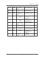
3.1. Introduction Instructions
3.1.1. Basic Instruction
Name
Load
Instruction
Ladder Symbol
LOAD
Description
Page
Operation starts from A contact
48
(Normal Open)
Load Not
LOADN
Operation starts from B contact
48
(Normal Close)
And
AND
A contact series connection
49
And Not
ANDN
B contact series connection
49
Or
OR
A contact parallel connection
50
Or Not
ORN
B contact parallel connection
50
And Stack
ANDS
AND connection between blocks
56
Or Stack
ORS
OR connection between blocks
57
Output
OUT
Output result of operation
51
Not
NOT
Reverse result of operation
54
Step
STEPSET
Output step controller
64
Sequential Set
(sequential control)
40
TinyPLC User’s Manual
Step Output
STEPOUT
Output step controller (LIFO)
65
Master Control
MCS
Start master control relay
61
MCSCLR
Terminate master control relay
61
DF
Output “ON” during 1 scan time if
60
Set
Master Control
Clear
Differential
input condition rise.
(differential input)
Differential Not
Output “OFF” during 1 scan time if
DFN
60
input condition pull down.
(differential reverse input)
Set Output
SETOUT
Set output of contact point ON
58
Reset Output
RSTOUT
Reset output of contact point OFF
59
Save Status
SAVES
No ladder
SAVE present operation state
-
Read Status
RDS
No ladder
Read saved state
-
SAVES and RDS are used
at ladder branch
End
END
End of program
41
47
TinyPLC User’s Manual
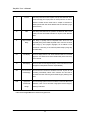
3.1.2. TIMER/COUNTER
Name
On Timer
Instruction
Ladder Symbol
TON
Description
Page
0.01sec ON delay timer
(10mS)
58
(maximum 327.67sec)
With input, timer starts to operate.
Without input, timer becomes
reset. In case timer value reaches
set point, point of contact becomes
On.
Off Timer
0.01 sec OFF delay timer
TOFF
59
(maximum 327.67 sec)
(10mS)
With
input,
point
of
contact
becomes On. In case input is cut,
point of contact is not directly Off.
And after set time passed, it
becomes Off
On Timer
TAON
0.1 sec ON delay timer
(100mS)
58
(maximum 3276.7 sec)
Operation is same with TON
command
Off Timer
TAOFF
0.1 sec OFF delay timer
(100mS)
59
(maximum 3276.7 sec)
Operation is same with TOFF
command
Up Counter
CTU
Up counter
60
(able to count to maximum 65535)
With input it augments by 1, and
then it reaches to set point, point of
contact becomes On. With reset
input, counter becomes 0.
Down Counter
CTD
Down counter
(able to count from maximum
65535)
With input it decays by1, and then it
reaches to 0, point of contact is set
to set point.
42
61
TinyPLC User’s Manual
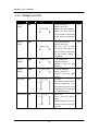
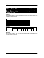
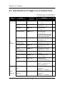
3.1.3. Comparing Command
Comparing command can be implemented in Tiny PLC to use command, which start with a sign of
inequality, to input symbol as shown below.
In case D0 = D2, point of contact becomes ON.
Only in case of D0 = D2,
this command is executed.
Classification
16 Bit comparing command
32 Bit comparing command
Instruction
Format
Description
Page
=, S1, S2
In case S1 = S2, point of contact becomes ON.
It compares 1 word (16 Bit) value.
63
>, S1, S2
In case S1 > S2, point of contact becomes ON.
63
<, S1, S2
In case S1 < S2, point of contact becomes ON.
63
<=, S1, S2
In case S1 <= S2, point of contact becomes ON.
63
>=, S1, S2
In case S1 >= S2, point of contact becomes ON.
63
<>, S1, S2
In case S1 ? S2, point of contact becomes ON.
In case S1 = S2, point of contact becomes ON.
It compares double word (32 Bit) value.
63
D>, S1, S2
In case S1 > S2, point of contact becomes ON.
65
D<, S1, S2
In case S1 < S2, point of contact becomes ON.
65
D<=,
S1,
In case S1 <= S2, point of contact becomes ON.
65
S1,
In case S1 >= S2, point of contact becomes ON.
65
S1,
In case S1 ? S2, point of contact becomes ON.
65
D=, S1, S2
65
S2
D>=,
S2
D<>,
S2
***S1, S2 mean argument1, argument 2.
AND and OR interface is free to be used with Comparing command, same as general point of contact
input.
43
TinyPLC User’s Manual
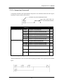
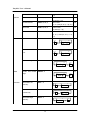
3.1.5. Bad Ladder Input
LOAD command should start from the first column (the very side of mother line).
Ladder should spread out as below.
Output symbol could not be located on the first column (the very side of left mother line).
44
TinyPLC User’s Manual
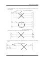
You cannot interface from one line to various output point of contact. In this case, you should correct as
below and input.
Over one branch processed as error
There should not occur collision of same output.
There occurs contradiction the same
output have different value
If you insert unnecessary blank (crossway), translation error occurs. (You should make it close without
blank.)
There should not be blank.
45
TinyPLC User’s Manual
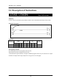
3.2. Description of Instructions
LOAD, LOADN
Start A/B contact
Summary
LOAD is start of A (Normally open) contact; LOADN is start command of B (Normally closed) contact.
Example of program
LOAD
LOADN
Operands
Command
LOAD
LOADN
Relay
P
M
F
K
S
C
time
r
T
O
O
O
O
O
O
O
O
O
O
O
O
O
O
counte
r
Etc.
AD
CH
constant
G
Descriptions in detail
If A contact P0:0 become ON, Output P1:0 become ON,.
If B contact become ON, Output P1:1 become ON,.
( P0:0 and P0:1for input should be set input on MPGL2 program. Same way, P1:0 and P1:1 for output
should be set output. Incase input/output set is wrong, it does not work right.)
46
TinyPLC User’s Manual
AND, AND
series interface of A/B contact
Summary
AND is series interface of A contact, ANDN is series interface command of B contact.
Example of program
ANDN
AND
Operands
Command
AND
ANDN
P
M
O
O
O
O
Relay
F K
O
O
O
O
Counter
Timer
S
C
T
O
O
O
O
O
O
AD
Description
If P0:0 and P0:1 become ON, output P1:1 become ON.
If B contact P0:2 become ON, output P1:1 become OFF.
47
Etc.
CH
Constant
G
TinyPLC User’s Manual
OR,ORN
interface of A/B contact
Summary
OR is parallel interface of A contact, ORN is parallel interface command of B contact.
Example of program
OR
ORN
Operands
Command
OR
ORN
P
Relay
M F K
O
O
O
O
O
O
O
O
S
Counter
C
Timer
T
O
O
O
O
O
O
AD
Description
If P0:0 or P0:1 or P0:2 become ON, output P1:1 become ON.
48
Etc.
CH
Constant
G
TinyPLC User’s Manual
OUT
output operation result
Summary
Do output the result of operation to contact point.
Example of program
OUT
Operands
Command
OUT
P
Relay
M F K
O
O
S
Counter
Timer
C
T
AD
O
Description
If P0:0 become ON, output P1:1 become ON.
49
Etc.
CH
Constant
G
TinyPLC User’s Manual
NOT
output of operation result
Summary
Reverse operation result before NOT.
Example of program
NOT
Description
If P0:1 become ON, output P1:1 become OFF. The upper program has the same effect as below.
The result will be same, even though remove NOT and change B contact.
50
TinyPLC User’s Manual
END
end of program
Summary
It shows the end of the entire program. (It should be always located on the end of program.)
Example of program
Description
MPGL2 translate as far as END instruction and deposit. Please be careful, all of the instructions which
made after END are ignored.
51
TinyPLC User’s Manual
ANDS
AND interface between block
Summary
It is series interface command between block.
Example of program
A Block
B Block
Description
When block A and block B are ON, output P1:0 become ON.
52
TinyPLC User’s Manual
ORS
OR interface between blocks
Summary
It is parallel interface command, between block.
Example of program
A Block
B Block
Description
When block A or block B is ON, output P1:0 become ON.
53
TinyPLC User’s Manual
SETOUT
maintain output ON
Summary
Maintain output point of contact ON.
Example of program
Operands
Command
SETOUT
P
Relay
M F K
O
O
S
Counter
Timer
C
T
AD
Etc.
CH
O
Description
If P0:0 become ON, P1:0 output point of contact maintain ON.
54
Constant
G
TinyPLC User’s Manual
RSTOUT
maintain output OFF
Summary
Maintain output point of contact OFF.
Example of program
Operands
Command
RSTOUT
P
Relay
M F K
O
O
S
Counter
Timer
C
T
AD
Etc.
CH
O
Description
If P0:1 become ON, maintain P1:0 output point of contact OFF.
55
Constant
G
TinyPLC User’s Manual
DF, DFN
differential input
Summary
DF : If rise edge of input condition (Off-->On) is verified, output point of condition become ON for 1 scan
time.
DFN : If pull-down edge of input condition (On-->Off) is verified, output point of condition become ON for
1 scan time.
Example of program
DF.
DFN.
Operands
Command
P
DF
DFN
M
Relay
F K
Counter
S
C
Timer
T
AD
Etc.
CH
Constant
G
O
O
* Caution: DF and DFN command should be used only at M .
Description
Time Chart
The moment P0:1 become ON, P1:0 become ON
for 1 scan time.
P0:1
The moment P0:2 become OFF, P1:1 become
P0:2
ON for 1 scan time.
M0:0 P1:0
1 SCAN
M0:1 P1:1
1 SCAN
56
TinyPLC User’s Manual
MCS, MCSCLR
master control relay
Summary
If input condition of MCS is ON, it executes until MCSCLR which have same number but is OFF, it does
not executes. In case it does not execute, all outputs in the range of MCS ~ MCSCLR become OFF.
Example of program
Number of MCS
Time Chart
Description
If P0:7 become ON, ladder in the range of MCS 1
~ MCSCLR 1 is executed. If P0:7 become OFF,
ladder in the range of MCS 1 ~ MCSCLR 1 is not
P0:7
P0:0
executed. Also output P1:0 and P1:1 become
OFF.
P0:1
MCS number is available to use from 0 to 7. 0
P1:0
have the highest priority and 7 have the lowest
P1:1
priority. Therefore, if you release MCS the
highest priority, the rest of MCS are also
released.
57
TinyPLC User’s Manual
The table below explains instructions influenced in MCS loop.
Instruction
OUT
SETOUT
RSTOUT
Timer instruction
(TON, TOFF..)
Counter instruction
(CTU, CTD)
The rest of instructions
MCS is ON
condition
Normal execution
Normal execution
Normal execution
Normal execution
MCS is OFF condition
Unconditional OFF
Maintain constantly the state before MCS become OFF
Maintain constantly the state before MCS become OFF
Reset initial value
Normal execution
Maintain constantly the state before MCS become OFF
Normal execution
Not execute
The nesting of MCS, MCSCLR instruction examples are described as below. (Nesting level is possible
until maximum 8 level. Certainly, do layout lower number first and then layout higher number
inside.)
58
TinyPLC User’s Manual
Caution
When you do not nest level, you should keep using MCS0.
Above diagram must be corrected as follows.
59
TinyPLC User’s Manual
STEPSET
step control (sequential control)
Summary
In case the previous number in same group is ON, present number becomes ON and previous number
become OFF. (It is called sequential control because it becomes ON in sequential order.) From 0 to 255
steps is available.
Example of program
Operands
Command
P
STEPSET
M
Relay
F K
Counter
S
C
Timer
T
AD
Etc.
CH
O
Description
Time Chart
If P0:2 become ON, 2 step of 0 group attempt to
P0:1
be ON. At that time, if 1 step of same group was
P0:2
ON, 1 step become OFF and 2 step become ON.
In case P0:3 become ON, unconditionally it put
P0:3
back in 0 step. (0 step is used for reset.)
S0:1
S0:2
60
Constant
G
TinyPLC User’s Manual
STEPOUT
step control (LIFO)
Summary
Even though lots of input is processed in the same group, only the last step become ON and the rest steps
become OFF. (The last step has the priority, and then it is called Last In First Out.) From 0 to 255 step is
available.
Example of program
Operands
Command
P
STEPOUT
M
Relay
F K
S
Counter
Timer
C
T
AD
Etc.
CH
Constant
G
O
Description
Time Chart
If P0:1 become ON, 1step of ) group become
P0:1
ON. After that, if P0:3 become ON, 0 step
P0:2
become ON. After that P0:2 become ON, 2 step
P0:3
become ON. Unconditionally, the last step
become ON only, and the rest steps become
S0:1
OFF.
S0:2
S0:0
61
TinyPLC User’s Manual
#1) Additional Description about Step Controller
C or assembly easily processes sequential control, but sometimes it cannot be implemented on PLC
because of the characteristic of scan time. Then the mode so called, “step controller” is made from this
cause. It is useful when it comes to process in regular sequence.
You can execute process in sequence as below, after process 1 is executed and then next step is ON,
and after process 2 is executed and then the next step is ON. (The program as shown below use timer
instead of process.)
Start signal
Process 1
Process 1 end
Process 2
Process 2 end
Process 3
Process 3 end
Step relay has self-storage function. (Before other input, maintain present state.)
In one group only one output is ON. (same concept with interlock)
In case of sequential control; It is able to move back only one column.(possible to be ON, incase the
previous number is ON)
Incase of LIFO ; Even though lots of input is processed, all is ignored and only the last one become ON.
62
TinyPLC User’s Manual
TON, TAON
Usage : TON
ON delay timer
t, n
Summary
If input condition become ON, timer start to move, and become OFF, timer is reset. If timer value reaches
set point, output point of contact becomes ON. There is two types of timer, which have different time unit.
Type of Timer
TON
TAON
Unit
0.01 sec
0.1 sec
Maximum value
327.68 sec
3276.8 sec
Example of program
Operands
Operand
P
Relay
M F K
Counter
S
Timer
C
T
t
n (set point)
Description
Data
D
AD
Etc.
CH
Constant
G
O
O
O
Time Chart
1s
After P0:1 become ON, if 1 sec go by, TO point
of contact become ON. After P0:2 become ON, if
P0:1
10 sec go by, T1 point of contact become ON.
T0
63
TinyPLC User’s Manual
TOFF, TAOFF
Usage : TOFF
OFF delay timer
t, n
Summary
Right after input condition become ON, output point of contact becomes ON. After that, even if input
becomes OFF, point of contact does not changed directly to OFF, but become OFF after set time passed.
There are tow types of timer, which have different time unit.
Type of Timer
TOFF
TAOFF
Units
0.01 sec
0.1 sec
Maximum value
327.68 sec
3276.8 sec
Example of program
Operands
Operand
Relay
P M F K
Counter
S
Timer
C
T
t (timer point of contact)
n (set point)
Description
Data
D
AD
Etc.
CH
Constant
G
O
O
O
Time Chart
1s
Right after P0:1 become ON, T0 become ON.
After P0:1 become OFF, if 1 sec go by, T0 point
P0:1
of contact become OFF.
T0
64
TinyPLC User’s Manual
CTU
Usage : CTU
UP counter
c, n
Summary
Each time of counter input, counter value augment by 1. If counter value is same as set point, output point
of contact become ON. If input is also processed after point of contact become ON, counter is augmented
continuously. (It is augmented until maximum 65535. Over 65535, counter starts again from 0, and state of
point of contact is maintained.) If reset input is processed, counter value become 0.
Example of program
Operands
Operand
Relay
Counter
P M F K S
C
c (counter point of
contact)
n (set point)
Timer
T
AD
Etc.
CH
Constant
G
O
O
Time Chart
Description
If P0:0 become ON 100 times, C0 point of
contact become ON.
Data
D
If P0:1 point of
contact become ON, counter is reset and
point of contact become OFF.
P0:1
P0:2
C0
65
O
TinyPLC User’s Manual
CTD
Usage : CTD
DOWN counter
c, n
Summary
Each time of counter input, counter value is decayed by1. If counter value become 0, output point of
contact become ON. If reset is input, counter value become set point. (It is set to the point of power-on.)
Example of program
Operands
Operand
Counter
P M F K S
c (counter point of
contact)
n (set point)
Timer
C
T
AD
Etc.
CH
Constant
G
O
O
Description
Time Chart
If P0:0 become ON 100 times, C0 point of
contact become ON.
Data
D
If P0:1 point of
contact become ON, 100 is set to counter
and point of contact become OFF.
P0:1
P0:2
C0
66
O
TinyPLC User’s Manual
Implementation of UP/DOWN Counter
Even though TinyPLC do not have special UP/DOWN counter command, if you input as shown
below, UP / DOWN counter is able to be implemented.
UP signal
Reset signal
DOWN signal
1 decay command
After differential P0:2 signal by DF command, execute WDEC, 1 decay command. Then counter CO
value is decayed by 1. You can use P0:0 as augment input and, P0:2 as decay input.
KEEP of Timer and Counter
If you see memory map, part of TIMER and COUNT (slash mark) is KEEP, which keep state during
the power failure. If you use this, timer (or counter) value under processing is not gone and kept
during the power failure, and after power-on it process continuously.
KEEP of Counter (In case TPC37, from C240 to
Caution: If you use KEEP of counter, you should use CTU command for counting the consecutive
value from power-off, because CTD command is initialized to corresponded value, in case of poweron.
67
TinyPLC User’s Manual
= , <>, >, <, >=, <=
word comparing command
Usage : =, s1, s2
Summary
In case it satisfies condition with comparing two of word value, point of contact becomes ON. There are
totally 6 of comparing command.
Comparing command
= , s1, s2
<> , s1, s2
>, s1, s2
<, s1, s2
>=, s1, s2
<=, s1, s2
Execution
In case s1 = s2 , point of contact becomes on.
In case s1 ? s2 , point of contact becomes on.
In case s1 > s2, point of contact becomes on..
In case s1 < s2, point of contact becomes on.
In case s1 >= s2, point of contact becomes on.
In case s1 <= s2, point of contact becomes on.
Example of program
68
TinyPLC User’s Manual
Operands
Operand
P
Relay
M F K
s1
s2
C
T
Data
D
O
O
O
O
O
O
Counter
S
Timer
AD
Etc.
CNT
O
O
O
O
Constant
CH
G
O
O
Description
In case D0 = D1, P1:0 become ON.
In case D0 ? D1, P1:1 become ON.
In case D0 > D1, P1:2 become ON. In case D0 < D1, P1:3 become ON. In case D0 >= D1, P1:4 become ON.
In case D0 <= D1, P1:5 become ON.
It is possible to use AND, OR interface as shown below.
In case C2 = 30 and C0 >= 100, P1:0 become ON. Also in case D1 < 3 and C0 >= 100, P1:0 become ON.
69
TinyPLC User’s Manual
D=, D<>, D>,
D<, D>=, D<=
double word
comparing command
Usage : D=, s1, s2
Summary
In case it satisfies condition with comparing two of double word value, point of contact becomes ON. There
are totally 6 of comparing command.
Comparing command
D= , s1, s2
D<> , s1, s2
D>, s1, s2
D<, s1, s2
D>=, s1, s2
D<=, s1, s2
Execution
In case s1 = s2 , point of contact becomes on.
In case s1 ? s2 , point of contact becomes on.
In case s1 > s2, point of contact becomes on..
In case s1 < s2, point of contact becomes on.
In case s1 >= s2, point of contact becomes on.
In case s1 <= s2, point of contact becomes on.
Operands
Operand
P
Relay
M F K
s1
s2
C
T
Data
D
O
O
O
O
O
O
Counter
S
Timer
AD
Etc.
CNT
O
O
O
O
Constant
CH
G
O
O
Description
All of executions are the same with “word comparing command” which is explained before, except
comparing double word (32 Bit value).
70
TinyPLC User’s Manual
Chapter 4
High Level Instruction
This chapter describes high level instructions of TinyPLC in detail.
71
TinyPLC User’s Manual
4.1. Introduction of High Level Instructions
“s” means source and “d” means destination.
“n” indicates number(or arbitrary number)
class
Function
Formation of
Description
Pg
instructions
Byte Move
MOVE s, d
Data move by 8bits
(s)
Byte
Complement
CMOVE s, d
Move
Word Move
76
--> (d)
Data complement move by 8bits
77
complement(s) --> (d)
WMOV s, d
Data move by 16bits
78
(s) --> (d)
Double Word Move
DWMOV s,d
Data move by 32bits
79
(s, s+1) ---> (d, d+1)
* For 32bits, high-level word is
saved at s, low-level at s+1 (this is
similar to other instructions)
Word Complement
WCMOV s,d
Move
Move
Instructions
Double Word
81
complement(s) --> (d)
DWCMOV s,d
Complement Move
Word Negative Move
Data complement move by 16bits
Data complement move by 32bits
82
complement (s, s+1) --> (d, d+1)
WNEG s,d
Data negative move by 16bits
83
Negative 2 (s) --> (d)
Double
DWNEG s,d
Word Negative Move
Word Exchange Move
Data negative move by 32bits
84
Negative 2 (s, s+1) --> (d, d+1)
WXCHG s,d
Data interchange by 16bits
85
(s) <--> (d)
Double Word Exchange
DWXCHG s,d
Move
Fill Move
Data interchange by 32bits
86
(s, s+1) <--> (d, d+1)
FMOV s,d,n
Data filling instructions
87
(s) -> number of n data from (d)
Group Move
GMOV s,d,n
Group transmit instructions
88
Number of n data from (s) --->
number of n data from (d)
Word Binary to BCD
WBCD s,d
code
Converting 16bit binary data into 4
89
Digit BCD code.
(16bit Binary ) ---> (4 digit BCD )
convert
Double Word Binary to
instructions
BCD code
DWBCD s,d
Converting 32bit binary data into 8
Digit BCD code
(32bit Binary ) ---> (8 digit BCD )
72
90
TinyPLC User’s Manual
Word BCD code to
WBIN s,d
Converting 4 Digit BCD code into
Binary
91
16bit binary data
(4 digit BCD ) ---> (16 bit Binary )
Double
Word
BCD
DWBIN s,d
code to Binary
Converting 8 Digit BCD code into
92
32bits binary data
(8 digit BCD ) ---> (32 bit Binary)
Word Increment
WINC d
Increment 1 for 16bits
93
(d) + 1 ---> (d)
Increment
&
Double Word Increment
DWINC d
Increment 1 for 32 bits
decrement
instructions
94
(d, d+1) + 1 --> (d, d+1)
Word Decrement
WDEC d
Decrement 1 for 16 bits
95
(d) + 1 ---> (d)
Double Word Decrement DWDEC d
Decrement 1 for 32 bits
96
(d, d+1) + 1 --> (d, d+1)
Word Addition
WADD s1, s2, d
Addition for 16bits
97
(s1) + (s2) --> (d)
Arithmetic
Double Word Addition
DWADD s1, s2, d
Calculation
Addition for 32 bits
98
(s1, s1+1) + (s2, s2+1) --> (d, d+1)
Word Subtraction
WSUB s1, s2, d
Subtraction for 16 bits
99
(s1) - (s2) --> (d)
Double Word
DWSUB s1, s2, d
Subtraction
Word Multiplication
Subtraction for 32 bits
100
(s1, s1+1) - (s2, s2+1) --> (d, d+1)
WMUL s1, s2, d
Multiplication by 16bits (result is 32
101
bits)
(s1) * (s2) --> (d, d+1)
Double Word
DWMUL s1, s2, d
Multiplication
Multiplication by 32bits (result is 64
102
bits) (s1, s1+1) * (s2, s2+1) --> (d,
d+1, d+2, d+3)
Word Division
WDIV s1, s2, d
Division for 16 bits
103
(s1) / (s2) -->(d) for share, (d+1) for
surplus
Double Word Division
DWDIV s1, s2, d
Division for 32 bits
104
(s1, s1+1) / (s2, s2+1) --> (d, d+1) for
share, (d+2, d+3) for surplus
Word AND
WAND s1, s2, d
AND for 16bits
105
(s1) AND (s2) --> (d)
Logic
Double Word AND
DWAND s1, s2, d
AND for 32bits
(s1, s1+1) AND (s2, s2+1) --> (d,
73
106
TinyPLC User’s Manual
d+1)
Operation
Word OR
WOR s1, s2, d
OR for 16bits
107
(s1) OR (s2) --> (d)
Double Word OR
DWOR s1, s2, d
OR for 32bits
108
(s1, s1+1) OR (s2, s2+1) --> (d, d+1)
Word XOR
WXOR s1, s2, d
XOR for 16bits
109
(s1) XOR (s2) --> (d)
Double Word XOR
DWXOR s1, s2, d
XOR for 32bits
110
(s1, s1+1) XOR (s2, s2+1) --> (d,
d+1)
Word Rotate Left
WROL d
111
CARRY
MSB
LSB
C
Double Word Rotate
DWROL d
112
CARRY
Left
Word Rotate Right
d
MSB
LSB
C
d
WROR d
113
MSB
CARRY
LSB
d
Rotate
Double Word Rotate
DWROR d
Word Rotate Left
114
MSB
Right
instructions
d
C
WRCL d
115
with Carry
MSB
LSB
C
d
DWRCL d
116
CARRY
Left with Carry
Word Rotate Right
CARRY
LSB
CARRY
Double Word Rotate
C
MSB
LSB
C
d
WRCR d
117
MSB
with Carry
LSB
d
74
CARRY
C
TinyPLC User’s Manual
Double Word Rotate
DWRCR d
118
MSB
Right with Carry
Bit Shift Left
CARRY
LSB
d
BSHL d,n
C
119
Bit shift left instruction
Shift (d) left by n bit
MSB
LSB
d
Bit Shift Right
BSHR d,n
0
Bit shift right instruction
120
Shift (d) right by n bit
MSB
LSB
d
0
Shift
Instruction
Word Shift Left
WSHL s1, s2
Word shift left instruction
121
Shift 1word to left from s1to s2
Word Shift Right
WSHR s1, s2
D0
D1
D2
1234H
5678H
9ABCH
D0
D1
D2
5678H
9ABCH
0000H
Word shift right instruction
122
Shift 1word to right from s1to s2
D0
D1
D2
1234H
5678H
9ABCH
D0
0000H
Convert
SEG s,d
D1
1234H
D2
5678H
Convert instruction for 7 SEGment
for 7 SEGment
123
Converts 16bit values in s to 4bite
data which can be indicated in
7segment
LCD area Clear
LCDCLS
Insert SPACE( ASCII code 20H) in
125
CH area (clears the LCD screen)
Display
LCD data Output
LCDOUT port,mode
instructions
Display output to LCD from data in
126
CH area.
SGN data Output
SGNOUT port
Display output to SGN from data in G
130
area.
String Store
STRING d,”string”
Store “string” character at d.
“string” --> (d)
75
133
TinyPLC User’s Manual
Word
Bin
HEX s,d
to
ASCII
Convert
HEX
ASCII
DHEX s,d
Convert
HEX
to
134
Word
32bit
binary value to
135
hexadecimal ASCII code.
format
(s, s+1) --> 4bytes from (d)
ASC s,d,n
Convert 16bit binary value to decimal
Bin to ASCII DEC
ASCII code.
format
(s, s+1) --> n bytes from (d)
Double Word
DASC s,d,n
Convert 32bit binary value to decimal
Bin to ASCII DEC
ASCII code.
format
(s, s+1) --> n bytes from (d)
Goto, LABEL
Jump
value
(s) --> 4bytes from (d)
Double Word
to
binary
hexadecimal ASCII code.
format
Bin
16bit
Subroutine CALL, RET
Looping
GOTO label
Jump instruction
LABEL label
Label definition instruction
CALLS label
Call subroutine
SBRT label
Define subroutine
RET
Return instruction
LOOP label, n
Repeat instruction, jump to label till n
136
137
138
139
141
is 0.
Key Matrix Scan
KEYSCAN
Key Matrix Scan instruction
142
maximum connection to 8 * 8
(64keys)
Used for connecting membrane key
panels.
Other
Output all off
OUTOFF
Off I/O port set to output
144
Distribute
DIST s,d,n
Distribute 16bit data by 4bit to d.
145
Combine
UNIT s,d,n
Combine 16bit data just including
146
Instruction
lower 4bits into 1word.
Encode
ENCO s,d
Encode lower 4bits of s and store at
147
d.
Decode
DECO s,d
Decode 16bits of s and store at
148
lower 4 bits.
Thermometer Input
THIN port, d
Measure current temperature from
Digital thermometer DS1820 and
store at d.
76
149
TinyPLC User’s Manual
4.2. Number system in TinyPLC
Before explaining High Level Instructions, the concept of number system and code (BCD code, ASCII
code) treated in TinyPLC should be explained first. There are binary, decimal and hexadecimal
numbers and marked as below.
decimal
0
1
2
3
4
5
6
7
8
9
10
11
12
13
14
binary
0000
0001
0010
0011
0100
0101
0110
0111
1000
1001
1010
1011
1100
1101
1110
Hexadecimal
0
1
2
3
4
5
6
7
8
9
A
B
C
D
E
15
1111
F
?
A binary number of four figures can be
expressed by one hexadecimal.
? A~F is used to express 10~15 in hexadecimal.
? Number expression at ladder program
- Binary: 00011010B
- Decimal: 123, 80
- Hexadecimal: 0ABH, 12345H
There are units as bit, byte, word and double word to classify the dimension of numbers.
Double Word
Word
Byte
Nibble
bit
Bit is the basic unit to express 1 and 0. 1 nibble is composed of 4bits. 1 byte is composed of 8bits and 1
word of 16bits.
77
TinyPLC User’s Manual
There are areas parted by byte unit and word unit in TinyPLC.
Area by byte
P area (in/output)
K area (KEEP)
M area (sub relay)
CH area (LCD display data)
G area (SGN data)
Area by word
T area (timer)
C area (counter)
D area (data)
AD area (AD result)
CNTarea (high speed counter value)
76543210
P0
P1
P2
:
P15
A
P area is parted by byte unit. P0:0 shows 0th bit (A spot) of P0
byte. This shows that the P0:8 is the wrong expression
because there is no spot after 8th bit.
D area in which data is stored is parted by word unit.
FEDCBA9876543210
D0
D1
D2
D3
D4
:
D1023
The instructions of arithmetic operation and logic operation in TinyPLC are basically in word unit.
There is “double word” instruction, which 2words are put together. In using double word, the
assigned word number is used with the next word number together.
For example, if you run DWMOV 12345678H, D0 (means store 12345678H in D0), D0 and D1 are
used together. Data is stored in byte order. The following figure shows the state of D0 how 12345678H
is stored.
0
7
D0
1
2
D1
3
5
4
6
7
8
78
4 bytes are used to store 12345678H.
TinyPLC User’s Manual
ASCII CODE
ASCII Code system is used for displaying and printing. 1byte indicates 1number. The following is the
table of ASCII code. (ASCII code of number 8 is 38H)
0
High
rank
4bit
2
3
4
5
6
7
0
@
P
`
p
1
!
1
A
Q
a
q
2
“
2
B
R
b
r
3
#
3
C
S
c
s
4
$
4
D
T
d
t
5
%
5
E
U
e
u
Lower rank 4bit
6
7
8
&
‘
(
6
7
8
F
G
H
V
W
X
f
g
h
v
w
x
9
)
9
I
Y
i
y
A
*
:
J
Z
j
z
B
+
;
K
[
k
{
C
,
<
L
\
l
|
D
=
M
]
m
}
E
.
>
N
^
n
F
/
?
O
_
o
BCD CODE
BCD (binary-coded decimal) code system represents decimal (0~9) numbers to binary 4BI (represents
a decimal number of one figure by 4bit unit).1byte can express 2 digit decimal number and 2 byte
4digit. The following chart shows BCD code.
decimal
0
1
2
3
4
5
6
7
8
9
BCD code
0000
0001
0010
0011
0100
0101
0110
0111
1000
1001
It is similar to the binary number, but the next example shows the difference between binary number
and BCD code.
Decimal (original number)
Transfer by binary
Transfer by BCD code
100
01100100 (64H)
000100000000 (100H)
79
TinyPLC User’s Manual
4.2. Description of high level instructions
MOVE
8BIT Move
Usage : MOVE
s, d
Summary
It is data transfer instruction by 8bit. Transfers the value (or 8bit constants)in s to d.
Example of program
Operands
operand
s (source)
d (destination)
Relay
P
M
O
O
O
O
F
K
O
O
S
counter
time
r
data
etc
C
T
D
AD
CNT
CH
G
O
O
O
O
O
O
O
O
O
O
O
O
O
O
Constant
O
Description
if the M:01 becomes ON, 100 is transferred to CH1. If M0:2 becomes ON, CH1 is transferred into G3. (Byte
can indicate 0~255)
Precautions in using C, T, D area:
As MOVE instruction transfers data by byte unit and C, T, D area by word unit, we need some precautions
in usage. If the instruction is “MOVE 100, DO”, 100 will be stored at the higher rank area of D0 and all the
values of D0 will be wrong. In this case, we must use WMOV instruction (word unit instruction) which
will be explained later.
80
TinyPLC User’s Manual
CMOVE
8bit Complement Move
Usage : CMOVE
s, d
Summary
It is data complement transfer instruction by 8bit. After completing the value (or 8bit constants) is s, it is
transferred to d.
Example of program
Operands
operand
s (source)
d (destination)
Relay
P
M
O
O
O
O
F
K
O
O
S
counte
r
C
time
r
T
data
Etc.
constant
D
AD
CNT
CH
G
O
O
O
O
O
O
O
O
O
O
O
O
O
O
O
Description
If M0:1 becomes ON, complement 100(155) is transferred to CH1. If M0:2 becomes ON, complement CH1
is transferred to G3.
decimal
01100100
64H (100)
hexadecimal
CH1
10011011
81
9BH (155)
TinyPLC User’s Manual
WMOV
16bit Move
Usage : WMOV
s, d
Summary
It is data transfer instruction by 16bit. The value (or 16bit constant) is transferred to d.
Example of program
Operands
operand
s (source)
d (destination)
P
M
Relay
F K
O
O
O
O
O
O
S
counter
timer
C
T
data
D
AD
Etc.
CNT
CH
G
constant
O
O
O
O
O
O
O
O
O
O
O
O
O
O
O
Description
If M0:1 becomes ON, 100 is transferred to D. If M0:2 becomes ON, C0 is transferred to D5. In using
constants, we can’t use over 65535. (Word can express 0~65535)
Precautions in using byte area:
As WMOV instruction transfers data by word unit and P,M,K by byte, we need some precautions in usage.
When we run WMOV, it executes by 2 bytes. For example, if you run “WMOV 1234H, CH0”, 12H is
stored at CH0 and 34H at CH1.
82
TinyPLC User’s Manual
DWMOV
Usage : DWMOV
32Bit Move
s, d
Summary
It is data transfer instruction by 32 bit. The value (or 32bit constants) in s is transferred to d.
Example of program
Operands
operand
s (source)
d (destination)
P
M
Relay
F K
O
O
O
O
O
O
S
counter
timer
C
T
data
D
AD
Etc.
CNT
CH
G
constant
O
O
O
O
O
O
O
O
O
O
O
O
O
O
Description
If M0 becomes ON, 0 is transferred to D0 and
HIGH byte
100 to D1. Figure beside shows that 100 is
stored at D1 and and 0 at D0.(higher area in
D0
D1
D2
D3
order)
you
cannot
(7FFF0000H
use
in
over
2,147,418,112
hexadecimal)
in
using
constants)
83
00H
00H
LOW byte
00H
64H
O
TinyPLC User’s Manual
About storage of byte, word and double word data…
There are three kinds of data transfer instruction.
Classification
Byte unit
Word unit
Double word unit
Transfer instruction
MOVE
WMOV
DWMOV
Complement transfer instruction
CMOVE
WCMOV
DWCMOV
Following shows the result of the instruction of transferring hexadecimal 12H to D0.
D0
D1
D2
D3
MOVE 100,D0
WMOV 100,D0
HIGH byte
HIGH byte
64H
LOW byte
D0
D1
D2
D3
00H
LOW byte
64H
Usable constant range by each unit is as follows.
Classification
Byte unit
Word unit
Double word unit
Range(decimal)
0~255
0~65535
0~2147418112
Range(hexadecimal)
0~0FFH
0~0FFFFH
0~7FFF0000H
Reference
Word instructions starts with W (example: WMOV)
Double word instructions start with DW (example: DWMOV)
84
DWMOV 100,D0
HIGH byte
D0
D1
D2
D3
00H
00H
LOW byte
00H
64H
TinyPLC User’s Manual
WCMOV
16bit complement move
Usage : WCMOV
s, d
Summary
It is complement transfer instruction by 16 bit.. Transfers the complement value in s (or 16bit constant) to d
Example of program
Operands
operand
s (source)
d (destination)
Relay
P
M
O
O
O
O
F
K
O
O
S
counter
time
r
data
Etc.
constant
C
T
D
AD
CNT
CH
G
O
O
O
O
O
O
O
O
O
O
O
O
O
O
O
Description
If M0:1 becomes ON, it transfers 65435(complement of 100) to D0. If M0:2 becomes ON, it transfers
complement C0 to D5. In using constants, over 65535 cannot be used. (word can express 0~65535)
85
TinyPLC User’s Manual
DWCMOV
Usage : DWCMOV
32bit complement move
s, d
Summary
It is 32bit complement transfer instruction. It transfers the complement value in s(or 32bit constant) to d.
Example of program
Operands
operand
s (source)
d (destination)
relay
P
M
O
O
O
O
F
K
O
O
S
counte
r
C
time
r
T
data
Etc.
D
AD
CNT
CH
G
O
O
O
O
O
O
O
O
O
O
O
O
O
O
HIGH byte
Description
If M0:1 becomes ON, it transfers 0 to D0 and
D0
D1
D2
D3
100 to D1. The figure beside shows the result.
86
0FFH
0FFH
constant
LOW byte
0FFH
09BH
O
TinyPLC User’s Manual
WNEG
16bit two’s complement move
Usage : WNEG
s, d
Summary
It is transfer instruction of complement, two’s. After converting s(or 16bit constant) by complement, two’s,
transfers to d.
Example of program
Operands
operand
S (source)
d (destination)
P
M
relay
F K
O
O
O
O
O
O
S
counter
timer
C
T
data
D
AD
Etc.
CNT
CH
G
constant
O
O
O
O
O
O
O
O
O
O
O
O
O
O
O
Description
If M0:1becomes ON, it transfers –100 (100 by complement, two’s) to D0. If M0:2 becomes ON, it transfers
C0 after converting by complement, two’s to D5.
What is complement, two’s?
In computers complement, two’s means negative number. Complement, two’s complements ordinary
numbers and add 1. (Complement, two’s of 1 is 0FFFFH.) As 1 + (-1) = 0, 1 + 0FFFFH is 0. Because of
this principal we can express all the negative numbers by using complement, two’s. In TinyPLC, there is
no actual negative instruction but you can use complement, two’s to express it.
87
TinyPLC User’s Manual
DWNEG
32bit two’s complement move
Usage : DWNEG
s, d
Summary
It is 32bit transfer instruction by complement two. It transfers values(or 32bit constants) in s by converting
complement two to d.
Example of program
Operands
operand
S (source)
d (destination)
relay
P
M
O
O
O
O
F
K
O
O
S
counte
r
C
time
r
T
data
etc.
constant
D
AD
CNT
CH
G
O
O
O
O
O
O
O
O
O
O
O
O
O
O
O
Description
If M0:1 becomes ON, it transfers –100 (100 by complement, two’s) to D0, D1. If M0:2 becomes ON, it
transfers C0,C1 after converting by complement, two to D5, D6.
88
TinyPLC User’s Manual
WXCHG
Usage : WXCHG
16bit data exchange
s, d
Summary
It is data exchange instruction by 16bit.. It exchanges the value in s with the value in d.
Example of program
Operands
operand
S (source)
d (destination)
P
relay
M F
K
O
O
O
O
O
O
counter
timer
C
T
data
D
AD
etc.
CNT
CH
G
O
O
O
O
O
O
O
O
O
O
O
O
O
O
S
constant
Description
If M0:1 becomes ON, it exchanges the value in D0 with in C0.
15
C0
1234H
15
D0
15
0
C0
0
7654H
15
0
7654H
D0
89
0
1234H
TinyPLC User’s Manual
DWXCHG
Usage : DWXCHG
32bit data exchange
s, d
Summary
It is data exchange instruction by 32bit.. It exchanges the value in s with the value in d.
Example of program
Operands
operand
s (source)
d (destination)
relay
P
M
O
O
O
O
F
K
O
O
S
counter
time
r
data
etc.
C
T
D
AD
CNT
CH
G
O
O
O
O
O
O
O
O
O
O
O
O
O
O
Description
If M0:1 becomes ON, it exchanges the values in D0, D1 with in C0, C1.
90
constant
TinyPLC User’s Manual
FMOV
Filling up data
Usage : FMOV
s, d, n
Summary
It fills up the value (or 16bit constants) in s from d by assigned number n.
Example of program
Operands
operand
relay
timer
data
C
T
D
AD
CNT
CH
G
O
O
O
O
O
O
O
O
O
O
O
O
O
O
counte
etc.
constan
t
r
S (source)
d (destination)
N(number)
P
M
O
O
O
O
F
K
S
O
O
O
O
Description
If M0:1 becomes ON, it stores value (16bit value) in C0 to D0, D1, D2, D3, D4.
15
C0
15
0
1234H
D0
D1
D2
D3
D4
D5
D6
D7
91
0
1234H
1234H
1234H
1234H
1234H
TinyPLC User’s Manual
GMOV
Group transfer
Usage : GMOV
s, d, n
Summary
It is the transfer instruction by group which can transfer various data. It transfers the assigned number (n)
of value from s to d.
Example of program
Operands
operand
S (source)
d (destination)
n (number)
relay
P
M
O
O
O
O
F
time
r
data
C
T
D
AD
CNT
CH
G
O
O
O
O
O
O
O
O
O
O
O
O
O
O
counter
K
S
O
O
etc.
constan
t
O
Description
If M0:1 becomes ON, it transfers C0-->D0, C1--> D1, C2-->D2, C3--> D3, C4--> D4.
HIGH byte
C0
C1
C2
C3
C4
C5
C6
C7
00H
01H
02H
03H
04H
05H
LOW byte
HIGH byte
64H
65H
66H
67H
68H
69H
D0
D1
D2
D3
D4
D5
D6
D7
92
00H
01H
02H
03H
04H
05H
LOW byte
64H
65H
66H
67H
68H
69H
TinyPLC User’s Manual
WBCD
16bit BIN to BCD convert
Usage : WBCD
s, d
Summary
It converts 16bit binary data to 4 digit BCD data.
Example of program
Operands
operand
S (source)
d (destination)
relay
P
M
O
O
O
O
F
K
S
O
O
counter
time
r
data
etc.
constant
C
T
D
AD
CNT
CH
G
O
O
O
O
O
O
O
O
O
O
O
O
O
O
Description
If M0:2 becomes ON, it stores the value in D0 to D4 after converting to 4digit BCD code.
HIGH byte
D0
D1
D2
D3
D4
D5
D6
D7
LOW byte
00H
64H
01H
00H
93
O
TinyPLC User’s Manual
DWBCD
32bit BIN to BCD convert
Usage : DWBCD
s, d
Summary
It converts 32bit binary data to 8 digit BCD data.
Example of program
Operands
operand
S (source)
d (destination)
relay
P
M
O
O
O
O
F
time
r
data
C
T
D
AD
CNT
CH
G
O
O
O
O
O
O
O
O
O
O
O
O
O
O
counter
K
S
O
O
etc.
constan
t
O
Description
If M0:1 becomes ON, it stores the value in D0,D1 to D4 after converting to 8digit BCD code. (0BC614EH is
12345678 in decimal number.)
HIGH byte
D0
D1
D2
D3
D4
D5
D6
D7
LOW byte
00H
61H
BCH
4EH
12H
56H
34H
78H
94
TinyPLC User’s Manual
WBIN
16bit BCD to BIN convert
Usage : WBIN
s, d
Summary
It converts 4 digit BCD data to 16bit binary data.
Example of program
Operands
operand
S (source)
d (destination)
relay
P
M
O
O
O
O
F
time
r
data
C
T
D
AD
CNT
CH
G
O
O
O
O
O
O
O
O
O
O
O
O
O
O
counter
K
S
O
O
etc.
constan
t
O
Description
If M0:2 becomes ON, it stores the value from D0 to D4 after converting from 4digit BCD code to binary
value.
HIGH byte
D0
D1
D2
D3
D4
D5
D6
D7
LOW byte
01H
00H
00H
64H
95
TinyPLC User’s Manual
DWBIN
32bit BCD to BIN convert
Usage : DWBIN
s, d
Summary
It converts 8 digit BCD data to 32bit binary data.
Example of program
Operands
operand
S (source)
d (destination)
relay
P
M
O
O
O
O
F
K
S
O
O
counter
time
r
data
etc.
constan
t
C
T
D
AD
CNT
CH
G
O
O
O
O
O
O
O
O
O
O
O
O
O
O
O
Description
If M0:2 becomes ON, it stores the value from D0 to D4 after converting 8digit BCD code to binary value.
HIGH byte
D0
D1
D2
D3
D4
D5
D6
D7
LOW byte
00H
34H
12H
56H
00H
E2H
01H
40H
96
TinyPLC User’s Manual
WINC
Increase 1 by 16bit
Usage : WINC
d
d=d+1
Summary
It is increase 1 instruction by 16bit.
Example of program
Operands
operand
relay
P
M
F
K
d
S
counter
time
r
data
C
T
D
AD
CNT
O
O
O
O
O
Description
If M0:1 becomes ON, 1 increase at D0.
( D0 = D0 + 1)
97
etc.
constant
CH
G
TinyPLC User’s Manual
DWINC
Increase 1 by 32bit
Usage : DWINC
d
d=d+1
Summary
It is increase 1 instruction by 32bit.
Example of program
Operands
operand
relay
P
M
F
K
S
d
counter
time
r
data
C
T
D
AD
CNT
O
O
O
O
O
Description
If M0:1 becomes ON, 1 increases at D0, D1.
( D0 ,D1 = D0,D1 + 1)
98
etc.
constan
t
CH
G
TinyPLC User’s Manual
WDEC
1 decrease by 16bit
Usage : WDEC
d
d=d-1
Summary
It is decrease 1 instruction by 16bit.
Example of program
Operands
operand
relay
timer
data
C
T
D
AD
CNT
O
O
O
O
O
counte
etc.
constan
t
r
P
M
F
K
d
S
Description
If M0:1 becomes ON, 1 decrease at D0.
(D0 = D0 - 1)
99
CH
G
TinyPLC User’s Manual
DWDEC
1 decrease by 32bit
Usage : DWDEC
d
d=d-1
Summary
It is decrease 1 instruction by 32bit.
Example of program
Operands
operand
relay
P
M
F
K
S
d
counter
time
r
data
C
T
D
AD
CNT
O
O
O
O
O
Description
If M0:1 becomes ON, 1 decreases at D0, D1.
(D0, D1 = D0, D1 - 1)
100
etc.
constan
t
CH
G
TinyPLC User’s Manual
WADD
Addition by 16bit
Usage : WADD
s1,s2, d
d = s1 + s2
Summary
It is addition instruction by 16bit. It stores the result of the addition of s1 and s2 at d.
Example of program
Operands
operand
relay
P
M
F
K
S
s1
s2
d
counter
time
r
data
etc.
C
T
D
AD
CNT
O
O
O
O
O
O
O
O
O
O
O
O
O
Description
If M0:1 becomes ON, it stores the result of the addition of D0 and D2 at D4.
HIGH byte
D0
D1
D2
D3
D4
D5
D6
D7
LOW byte
00H
12H
00H
34H
00H
46H
101
constant
CH
G
O
O
TinyPLC User’s Manual
DWADD
Addition by 32bit
Usage : DWADD
s1,s2, d
d = s1 + s2
Summary
It is addition instruction by 32bit. It stores the result of the addition of s1 and s2 at d.
Example of program
Operands
operand
relay
P
M
F
K
s1
s2
d
S
counter
time
r
data
etc.
C
T
D
AD
CNT
O
O
O
O
O
O
O
O
O
O
O
O
O
constan
t
CH
G
Description
If M0:1 becomes ON, it stores the result of the addition of D0, D1 and D2, D3 at D4 and D5.
HIGH byte
D0
D1
D2
D3
D4
D5
D6
D7
00H
03H
00H
04H
00H
07H
LOW byte
01H
12H
02H
34H
03H
46H
102
O
O
TinyPLC User’s Manual
WSUB
Subtraction by 16bit
Usage : WSUB
s1,s2, d
d = s1 - s2
Summary
It is subtraction instruction by 16bit. It stores the result of subtraction from s1 to s2 at d.
Example of program
Operands
operand
relay
timer
data
C
T
D
AD
CNT
O
O
O
O
O
O
O
O
O
O
O
O
O
counte
etc.
constan
t
r
P
M
F
K
s1
s2
d
S
Description
If M0:1 becomes ON, it stores the result of subtraction from D0 to D2 at D4.
HIGH byte
D0
D1
D2
D3
D4
D5
D6
D7
LOW byte
34H
56H
12H
34H
22H
22H
103
CH
G
O
O
TinyPLC User’s Manual
DWSUB
32bit subtract
Usage : DWSUB
s1,s2, d
d = s1 - s2
Summary
It is subtraction instruction by 32bit. It stores the result of subtraction from s1 to s2 at d.
Example of program
Operands
operand
relay
P
M
F
K
s1
s2
d
S
counter
time
r
data
etc.
C
T
D
AD
CNT
O
O
O
O
O
O
O
O
O
O
O
O
O
constan
t
CH
G
Description
If M0:1 becomes ON, it stores the result of subtraction from D0, D1 to D2, D3 at D4, D5.
HIGH byte
D0
D1
D2
D3
D4
D5
D6
D7
34H
78H
12H
56H
22H
22H
LOW byte
56H
9AH
34H
78H
22H
22H
104
O
O
TinyPLC User’s Manual
WMUL
16bit multiplication
Usage : WSUB
s1,s2, d
d = s1 * s2
Summary
It is 16bit multiplication instruction. It stores the multiplication result of s1 s2 at d by 32bit.
Example of program
Operands
operand
relay
P
M
F
K
s1
s2
d
S
counter
time
r
data
etc.
C
T
D
AD
CNT
O
O
O
O
O
O
O
O
O
O
O
O
O
constan
t
CH
G
O
O
Description
If M0:1 becomes ON, it stores the multiplied value of D0 and D2 at D4 by 32bit. (you need precaution as
the result is by double word unit).
HIGH byte
D0
D1
D2
D3
D4
D5
D6
D7
LOW byte
01H
23H
04H
56H
00H
EDH
04H
C2H
105
TinyPLC User’s Manual
DWMUL
32bit multiplication
Usage : DWSUB
s1,s2, d
d = s1 * s2
Summary
It is 32bit multiplication instruction. It stores the multiplication result of s1 s2 at d by 64bit.
Example of program
Operands
operand
relay
P
M
F
K
s1
s2
d
S
counter
time
r
data
etc.
C
T
D
AD
CNT
O
O
O
O
O
O
O
O
O
O
O
O
O
constan
t
CH
G
O
O
Description
If M0:1 becomes ON, it stores the multiplied value of D0, D1 and D2, D3 at D4, D5, D6, and D7 by 64bit.
HIGH byte
D0
D1
D2
D3
D4
D5
D6
D7
00H
34H
00H
33H
00H
00H
7FH
FDH
LOW byte
12H
56H
33H
33H
00H
00H
70H
6CH
106
TinyPLC User’s Manual
WDIV
16bit division
Usage : WDIV
s1,s2, d
d = s1 / s2
Summary
It is division instruction by 16bit. It stores the quotient of s1 divided by s2 at d and remainder at d+1.
Example of program
Operands
operand
relay
timer
data
C
T
D
AD
CNT
O
O
O
O
O
O
O
O
O
O
O
O
O
counte
etc.
constan
t
r
P
M
F
K
s1
s2
d
S
CH
G
Description
If M0:1 becomes ON, it stores the quotient of D0 divided by D1 at D4 and remainder at D5.
HIGH byte
D0
D1
D2
D3
D4
D5
D6
D7
LOW byte
12H
34H
00H
03H
06H
00H
11H
01H
107
O
O
TinyPLC User’s Manual
DWDIV
32bit division
Usage : DWDIV
s1,s2, d
d = s1 / s2
Summary
It is division instruction by 32bit. It stores the quotient of s1 divided by s2 at d and remainder at d+1.
Example of program
Operands
operand
relay
counter
time
data
etc.
constan
t
r
P
M
F
K
S1
S2
d
S
C
T
D
AD
CNT
O
O
O
O
O
O
O
O
O
O
O
O
O
CH
G
O
O
Description
If M0:1 becomes ON, it stores the quotient of D0, and D1 divided by D2, D3 at D4, D5 and remainder at D6,
D7.
HIGH byte
D0
D1
D2
D3
D4
D5
D6
D7
12H
56H
00H
00H
02H
C3H
00H
00H
LOW byte
34H
78H
00H
07H
99H
35H
00H
05H
108
TinyPLC User’s Manual
WAND
16BIT AND Operation
Usage : WAND
s1,s2, d
d = s1 and s2
Summary
It is 16bit AND instruction. It stores the result of AND operation of s1 and s2 at d.
Example of program
Operands
operand
relay
counter
time
data
etc.
constan
t
r
P
M
F
K
s1
s2
d
S
C
T
D
AD
CNT
O
O
O
O
O
O
O
O
O
O
O
O
O
CH
Description
If M0:1 becomes ON, it stores the result of D0 and D2 by AND operation at D4.
HIGH byte
D0
D1
01010101
LOW byte
01010101
AND
D2
D3
11110000
11110000
D4
D5
01010000
01010000
109
G
O
O
TinyPLC User’s Manual
DWAND
32bit AND operation
Usage : DWAND
s1,s2, d
d = s1 and s2
Summary
It is 32bit AND instruction. It stores the result of AND operation of s1 and s2 at d.
Example of program
Operands
operand
relay
P
M
F
K
s1
s2
d
S
counter
time
r
data
etc.
C
T
D
AD
CNT
O
O
O
O
O
O
O
O
O
O
O
O
O
constan
t
CH
G
Description
If M0:1 becomes ON, it stores the result of D0, D1 and D2, D3 by AND operation at D4, D5.
HIGH byte
D0
D1
01010101
01010101
LOW byte
01010101
01010101
AND
D2
D3
11110000
00001111
11110000
00001111
D4
D5
01010000
00000101
01010000
00000101
110
O
O
TinyPLC User’s Manual
WOR
16BIT OR Operation
Usage : WOR
s1,s2, d
d = s1 or s2
Summary
It is 16bit OR instruction. It stores the result of OR operation of s1 and s2 at d.
Example of program
Operands
operand
RELAY
P
M
F
time
r
data
C
T
D
AD
CNT
O
O
O
O
O
O
O
O
O
O
O
O
O
counter
K
s1
s2
d
S
etc.
Description
If M0:1 becomes ON, it stores the result of D0 and D2 by OR operation at D4.
HIGH byte
D0
D1
LOW byte
01010101
01010101
OR
D2
D3
11110000
11110000
D4
D5
11110101
11110101
111
constan
t
CH
G
O
O
TinyPLC User’s Manual
DWOR
32bit OR Operation
Usage : DWOR
s1,s2, d
d = s1 or s2
Summary
It is 32bit OR instruction. It stores the result of OR operation of s1 and s2 at d.
Example of program
Operands
operand
relay
P
M
F
K
s1
s2
d
S
counter
time
r
data
etc.
C
T
D
AD
CNT
O
O
O
O
O
O
O
O
O
O
O
O
O
constant
CH
G
Description
If M0:1 becomes ON, it stores the result of D0,D1 and D2,D3 by OR operation at D4,D5.
HIGH byte
D0
D1
01010101
01010101
LOW byte
01010101
01010101
OR
D2
D3
11110000
00001111
11110000
00001111
D4
D5
11110101
01011111
11110101
01011111
112
O
O
TinyPLC User’s Manual
WXOR
16bit XOR operation
Usage : WXOR
s1,s2, d
d = s1 xor s2
Summary
It is 16bit XOR instruction. It stores the result of XOR operation of s1 and s2 at d.
Example of program
Operands
operand
RELAY
P
M
F
time
r
data
C
T
D
AD
CNT
O
O
O
O
O
O
O
O
O
O
O
O
O
counter
K
S1
s2
d
S
etc.
Description
If M0:1 becomes ON, it stores the result of D0 and D2 by XOR operation at D4.
HIGH byte
D0
D1
01010101
LOW byte
01010101
XOR
D2
D3
11110000
11110000
D4
D5
10100101
10100101
113
constan
t
CH
G
O
O
TinyPLC User’s Manual
DWXOR
32BIT XOR Operation
Usage : DWXOR
s1,s2, d
d = s1 xor s2
Summary
It is 32bit XOR instruction. It stores the result of XOR operation of s1 and s2 at d.
Example of program
Operands
operand
RELAY
P
M
F
K
s1
s2
d
S
counter
time
r
data
etc.
C
T
D
AD
CNT
O
O
O
O
O
O
O
O
O
O
O
O
O
constant
CH
G
Description
If M0:1 becomes ON, it stores the result of D0, D1 and D2, D3 by XOR operation at D4, D5.
HIGH byte
D0
D1
01010101
01010101
LOW byte
01010101
01010101
XOR
D2
D3
11110000
00001111
11110000
00001111
D4
D5
10100101
01011010
10100101
01011010
114
O
O
TinyPLC User’s Manual
WROL
16BIT ROTATE LEFT
Usage : WROL
d
d = d << 1
Summary
It is rotate left instruction by 16bit. It rotates d to left by one bit.
Example of program
Operands
operand
relay
timer
data
C
T
D
AD
CNT
CH
G
O
O
O
O
O
O
O
counte
etc.
constan
t
r
d
P
M
O
O
F
K
O
S
Description
If M0:1 becomes ON, it rotates D0 to left by one bit. The value in bit(MSB) of highest level moves to CARRY
bit.
CARRY
MSB
LSB
C
d
115
TinyPLC User’s Manual
DWROL
32 BIT ROTATE LEFT
Usage : DWROL
d
d = d << 1
Summary
It is rotate left instruction by 32bit. It rotates d to left by one bit.
Example of program
Operands
operand
d
relay
P
M
O
O
time
r
data
C
T
D
AD
CNT
CH
G
O
O
O
O
O
O
O
counter
F
K
O
S
etc.
constan
t
Description
If M0:1 becomes ON, it rotates D0, D1 to left by one bit. The value in bit (MSB) of the highest level moves to
CARRY bit.
CARRY
MSB
LSB
C
d
116
TinyPLC User’s Manual
WROR
16BIT ROTATE right
Usage : WROR
d
d = d >> 1
Summary
It is rotate right instruction by 16bit. It rotates d to right by one bit.
Example of program
Operands
operand
relay
timer
data
C
T
D
AD
CNT
CH
G
O
O
O
O
O
O
O
counte
etc.
constan
t
r
d
P
M
O
O
F
K
S
O
Description
If M0:1 becomes ON, it rotates D0 to right by one bit. The value in bit (LSB) of the lowest level moves to
CARRY bit.
MSB
LSB
CARRY
C
d
117
TinyPLC User’s Manual
DWROR
32 BIT ROTATE right
Usage : DWROR
d
d = d >> 1
Summary
It is rotate right instruction by 32bit. It rotates d to right by one bit.
Example of program
Operands
operand
d
relay
P
M
O
O
F
K
S
O
counter
time
r
data
etc.
constan
t
C
T
D
AD
CNT
CH
G
O
O
O
O
O
O
O
Description
If M0:1 becomes ON, it rotates D0, D1 to right by one bit. The value in bit (LSB) of the lowest level moves to
CARRY bit.
MSB
LSB
CARRY
C
d
118
TinyPLC User’s Manual
WRCL
16bit rotate left(including Carry)
Usage : WRCL
d
d = d << 1 with C
Summary
It is rotate left instruction by 16bit. It rotates d including carry to left by one bit.
Example of program
Operands
operand
d
relay
P
M
O
O
F
data
C
time
r
T
D
AD
CNT
CH
G
O
O
O
O
O
O
O
counter
K
O
S
etc.
constant
Description
If M0:1 becomes ON, it rotates D0 with carry flag to right by one bit. The value in bit (MSB) of the highest
level moves to CARRY bit.
CARRY
MSB
C
LSB
d
119
TinyPLC User’s Manual
DWRCL
32 bit rotate left(including Carry)
Usage : DWRCL
d
d = d << 1 with C
Summary
It is rotate left instruction by 32bit. It rotates d including carry to left by one bit.
Example of program
Operands
operand
d
relay
P
M
O
O
F
K
O
S
counter
time
r
data
etc.
constan
t
C
T
D
AD
CNT
CH
G
O
O
O
O
O
O
O
Description
If M0:1 becomes ON, it rotates D0,D1 with carry flag to left by one bit. The value in bit(MSB) of the highest
level moves to CARRY bit.
CARRY
MSB
C
LSB
d
120
TinyPLC User’s Manual
WRCR
16 bit rotate right(including Carry)
Usage : WRCR
d
d = d >> 1 with C
Summary
It is rotate right instruction by 16bit. It rotates d including carry to right by one bit.
Example of program
Operands
operand
d
relay
P
M
O
O
F
K
O
S
counter
time
r
data
etc.
constan
t
C
T
D
AD
CNT
CH
G
O
O
O
O
O
O
O
Description
If M0:1 becomes ON, it rotates D0 with carry to right by one bit. The value in bit(LSB) of the lowest level
moves to CARRY bit.
MSB
LSB
d
CARRY
C
121
TinyPLC User’s Manual
DWRCR
32bit rotate right(including Carry)
Usage : DWRCR
d
d = d >> 1 with C
Summary
It is rotate right instruction by 16bit. It rotates d including CARRY to right by one bit.
Example of program
Operands
operand
d
RELAY
P
M
O
O
F
time
r
data
C
T
D
AD
CNT
CH
G
O
O
O
O
O
O
O
counter
K
O
S
etc.
constan
t
Description
If M0:1 becomes ON, it rotates D0,D1 with CARRY to right by one bit. The value in bit(LSB) of the lowest
level moves to CARRY bit.
MSB
LSB
d
CARRY
C
122
TinyPLC User’s Manual
BSHL
Shift left by bit unit
Usage : BSHL
d,n
d = d << n
Summary
It is shift left instruction by bit unit. It shifts d to left by n bit. The newly inserted bit is set to 0.
Example of program
Operands
operand
d
n
relay
P
M
O
O
F
K
O
S
counter
time
r
data
etc.
constan
t
C
T
D
AD
CNT
CH
G
O
O
O
O
O
O
O
O
Description
If M0:1 becomes ON, it rotates D0 to left by 4 bit. The bits of highest level give way (disappear), and the bits
of lowest level are set to 0.
HIGH byte
LOW byte
D0
D1
00001111
1110 0011
D2
D3
11111110
00110000
123
TinyPLC User’s Manual
BSHR
Shift right by bit unit
Usage : BSHR
d,n
d = d >> n
Summary
It is shift right instruction by bit unit. It shifts d to right by n bit. The newly inserted bit is set to 0.
Example of program
Operands
operand
d
relay
P
M
O
O
F
time
r
data
C
T
D
AD
CNT
CH
G
O
O
O
O
O
O
O
counter
K
O
S
etc.
constant
Description
If M0:1 becomes ON, it rotates D0 to right by 4 bit. The bits of the highest level give way (disappear), and
the bits of lowest level are set to 0.
HIGH byte
LOW byte
D0
D1
00001111
1110 0011
D2
D3
00000000
11111110
124
TinyPLC User’s Manual
WSHL
Shift left by word unit
Usage : BSHL
s1,s2
Summary
It is shift left instruction by word unit. It shifts from s1 to s2 left by 1 word. The newly inserted word is set to
0.
Example of program
Operands
operand
s1,s2
relay
P
M
O
O
F
K
S
O
counter
time
r
data
etc.
constan
t
C
T
D
AD
CNT
CH
G
O
O
O
O
O
O
O
Description
If M0:1 becomes ON, it rotates from D0 to D0 left by 1 word. D0 disappears and D2 is set to 0.
D0
D1
D2
1234H
5678H
9ABCH
D0
D1
D2
5678H
9ABCH
0000H
125
TinyPLC User’s Manual
WSHR
Shift right by word unit
Usage : BSHR
s1,s2
Summary
It is shift right instruction by word unit. It shifts from s1 to s2 right by 1 word. The newly inserted word is
set to 0.
Example of program
Operands
operand
s1,s2
relay
P
M
O
O
F
K
S
O
counter
time
r
data
etc.
constan
t
C
T
D
AD
CNT
CH
G
O
O
O
O
O
O
O
Description
If M0:1 becomes ON, it rotates from D0 to D0 right by 1 word. D0 disappears and D2 is set to 0.
D0
D1
D2
1234H
5678H
9ABCH
D0
D1
D2
0000H
1234H
126
5678H
TinyPLC User’s Manual
SEG
Convert data for 7 segment
Usage : SEG
s,d
Summary
It converts 16bit data in s to 4 digit data for 7 segment.
Example of program
Operands
operand
relay
timer
data
C
T
D
AD
CNT
CH
G
O
O
O
O
O
O
O
O
O
O
O
O
O
O
counte
etc.
constan
t
r
s
d
P
M
O
O
O
O
F
K
S
O
O
O
Description
It is data convert instruction for 7 segment. If M0:1 becomes ON, it stores the 16bit data in D0, after
converting to 4digit data for 7 segment, by 2 words(4byte).
D0
D2
01110111
01111100
A
B
D3
127
1010
1011
1100
1101
A
B
C
D
00111001
C
01011110
D
TinyPLC User’s Manual
a
f
h
c
e
d
hexadecimal
0
1
2
3
4
5
6
7
8
9
A
B
C
D
E
F
Dp
0
0
0
0
0
0
0
0
0
0
0
0
0
0
0
0
g
0
0
1
1
1
1
1
0
1
1
1
1
0
1
1
1
f
1
0
0
0
1
1
1
1
1
1
1
1
1
0
1
1
e
1
0
1
0
0
0
1
0
1
0
1
1
1
1
1
1
d
1
0
1
1
0
1
1
0
1
1
0
1
1
1
1
0
c
1
1
0
1
1
1
1
1
1
1
1
1
0
1
0
0
b
b
1
1
1
1
1
0
0
1
1
1
1
0
0
1
0
0
a
1
0
1
1
0
1
1
1
1
1
1
0
1
0
1
1
Dp
By 7 segment
0
1
2
3
4
5
6
7
8
9
A
B
C
D
E
F
There are two kinds of method to drive segments in TinyPLC. First method is to connect segment directly
to I/O port using SEG instruction, and the second is to use special SGN (Serial segment module which is
marketed in Comfile)
It is efficient to use SEG instruction if there are only 1 or 2 segments to drive, but it also has the weak point
of using many ports. If we use SGN module we can save the port because only 1 I/O port is used, and can
control many segments by 1 line as 1 line can connect 8 SGN modules (7 segments of 40). (For more details
of SGN, refer to SGNOUT instruction description)
128
TinyPLC User’s Manual
LCDCLS
Clear LCD Screen
Usage : LCDCLS
Summary
Fill CH of LCD display area with 20H (SPACE in ASCII code).
Example of program
Description
Fill CH of LCD display area with 20H (SPACE in ASCII code).
There is no effect in LCD without LCDOUT instruction. It is the instruction of clearing only CH area.
129
TinyPLC User’s Manual
LCDOUT
LCD transmission start
Usage : LCDOUT port, mode
Summary
Transmit data on CH area to serial module.
n
n
Port describes port locations connected to a LCD module (e.g.: P0:4)
Modes are types of connected LCD.
0: 16 by 2 English LCD module (ELCD162)
1: 16 by 4 English LCD module (ELCD164)
2: 20 by 4 English LCD module (ELCD204)
3: Korean LCD (HLCD112 or HLCD114)
Example of program
Special relay turning ON every 1 second
Output port for
LCD data (this port
should be set up
for output.)
Differentiate
in
order to run every
one second
Description
F4:0 is a special relay repeating ON/OFF every one second. And F4:0 differentiates and makes LCDOUT
runs every one second. LCDOUT instruction transmits data on CH area to LCD. Once LCDOUT
instruction is given, all data on CH area transmits to LCD. (It takes about 200mS~500mS)
Be careful not to transmit during other transmissions. Therefore, you have to use a method transmitting
data every one second like above example or program to show when you press down a key.
Only serial LCD products made by Compile Co. can be used for LCD modules. Serial module should be
set up in 19200 mode (It should be set up with jumpers.).
130
TinyPLC User’s Manual
About serial English LCD modules...
A serial LCD modules manufactured by Compile Co. are different from other existing LCD modules in the
way that it connects with three electric lines. (The existing way is a parallel connection with 14 electric lines.)
RX
+5V
GND
Two of three electric lines are power electric line (+5V, GND) and the rest transmits data. Data use RS232C
of 5V level and 19200 baud rate and you can indicate letters on an designated position by transmitting
ASCII cord. LCDOUT instruction of TinyPLC transmits all the data (ASCII cord) on CH area to RS232.
A position on LCD is closely related to H location. When you record on CH0, it appears first line on the left
side. The following shows the relationship between 16 by 2 LCD and CH area.
CH CH CH CH CH CH CH CH CH CH CH CH CH CH CH CH
0 1 2 3 4 5 6 7 8 9 10 11 12 13 14 15
CH CH CH CH CH CH CH CH CH CH CH CH CH CH CH CH
20 21 22 23 24 25 26 27 28 29 30 31 32 33 34 35
The first line is assigned from CH0 and the second line is assigned from CH20. In using 16 by2, LCD
doesn’t show if you save data on CH40~79 area.
131
TinyPLC User’s Manual
The following is the case of 20 by 4 lines. (20 by 4 LCD can show all the 80 bytes on CH area.)
CH CH CH CH CH CH CH CH CH CH CH CH CH CH CH CH CH CH CH CH
0 1 2 3 4 5 6 7 8 9 10 11 12 13 14 15 16 17 18 19
CH CH CH CH CH CH CH CH CH CH CH CH CH CH CH CH CH CH CH CH
20 21 22 23 24 25 26 27 28 29 30 31 32 33 34 35 36 37 38 39
CH CH CH CH CH CH CH CH CH CH CH CH CH CH CH CH CH CH CH CH
40 41 42 43 44 45 46 47 48 49 50 51 52 53 54 55 56 57 58 59
CH CH CH CH CH CH CH CH CH CH CH CH CH CH CH CH CH CH CH CH
60 61 62 63 64 65 66 67 68 69 70 71 72 73 74 75 76 77 78 79
The table below shows serial modules able to be connected to PLC.
Model
ELCD162
ELCD162-BL
ELCD164
ELCD164-BL
ELCD204
ELCD204-BL
ELCD162-BIG-BL
HLCD112-BL
HLCD114-BL
Product
16 by 2 English LCD
16 by 2 English LCD back right
16 by 4 English LCD
16 by 4 English LCD back right
20 by 4 English LCD
20 by 4 English LCD back right
Double size
16 by 2 English LCD back right
Korean LCD
11 by 2 line back right
Korean LCD
11 by 4 line back right
Screen size (mm)
64.5 * 13.8
64.5 * 13.8
61.8 * 25.2
61.8 * 25.2
76 * 25.2
76 * 25.2
99 * 36
60.5 * 18.5
70.7 * 38.8
Additional information
If you change output port, you can run several LCD modules simultaneously. In running several LCD
simultaneously, you should make sure if output times (200~500mS) don’t conflict with each other. (This is
applied same to SGNOUT instruction.)
132
TinyPLC User’s Manual
SGNOUT
Usage : SGNOUT
SGN transmission start
port, n
Summary
Data on G area is transmitted by serial seven segment module (SGN). Port describe the port location
connected to a LCD module (Example P0:5), n is number of SGN module.
* SGN is the registered trademark of Compile Technology. (Seven seGment Network)
Example of program
Special relay turning on every 1 second
Differentiate in order to run every
SGN data output port (This
port should be set up for
output.) and number of
SGN.
one second
Description
F4:0 is a special relay repeating ON/OFF every one second. And F4:0 differentiates and makes SNGOUT
instruction run every one. SGNOUT instruction transmits data on G area to SGN. Once SGNOUT
instruction is given, all the data on G area transmits to SGN. (It takes about 50mS~100mS)
Be careful not to transmit during other transmissions. Therefore, you have to use a method transmitting
data every one second like above example or program to show when you press down a key.
Since maximum five seven segments are equipped at one SGN and maximum eight SGN modules can be
connected to each other, on I/O port can control 40 seven segment at maximum.
133
TinyPLC User’s Manual
About SGN modules...
SGN module is a seven segment display module manufactured by Compile Technology. (SGN is an
abbreviation of Seven seGment Network) The dynamic display is generally used in operate seven
segment, but it is not convenient in the way it needs many electric lines and good operating timing. SGN
module equipped on PCB with the chip operating maximum five units of seven segment and it shows on
the designated point when RS232C of 5V level and 9600 baud rate transmit data.
TinyPLC got SGN instruction which runs this kind of SGN modules and, it can be installed simply by
connecting one of I/O ports to SGN.
RX
+5V
GND
Separate ports are available for SGN module connections and one I/O port can control maximum eight
SGN modules.
One the back side of SGN module is there DIP switches which set each address. G area is allocated
according to DIP switch setting.
DIP switch
0000
0001
0010
0011
0100
0101
0110
0111
G area allocation
G0 ~ G4
G5 ~ G9
G10 ~ G14
G15 ~ G19
G20 ~ G24
G25 ~ G29
G30 ~ G34
G35 ~ G39
When one SGN module is used, location 0 on G area is allocated to first seven segment from the left.
134
TinyPLC User’s Manual
G0 G1 G2 G3 G4
Therefore, if 31H is on G0 (1 in ASCII cord) , 32H is on G1, 33H is on G2, 34H is on G3, 35H is on G4 and
SGNOUT instruction is given, the result comes out as follows;
In order to output data on SGN, you should save the designated data (in ASCII cord) from G area by using
ASC, HEX or STRING and then transmit it to SGNOUT.
The below SGN modules are available at present. (August, 19999)
Model
SGN-S3
SGN-S4
SGN-S5
SGN-M3
SGN-M4
SGN-M5
Product
SGN SMALL 3 DIGIT module
SGN SMALL 4 DIGIT module
SGN SMALL 5 DIGIT module
SGN MIDDLE 3 DIGIT
module
SGN MIDDLE 4 DIGIT
module
SGN MIDDLE 5 DIGIT
module
Total size(mm)
80 * 19.4
80 * 19.4
80 * 19.4
163 * 42
163 * 42
163 * 42
You can also take a look at detailed specification of SGN modules and LCD modules (life-size photos) on
our homepage http:// www.comfile.co.kr.
135
TinyPLC User’s Manual
STRING
characters line saving
Usage : STRING
d,”string”
Summary
Save character line “string” to d according to the number of line.
Example of program
Operands
Offer land
Relay
P
M
F
K
S
Counte
r
Timer
Data
C
T
D
d
O
Others
AD
CNT
Coeff.
CH
G
O
O
Description
This is a character line saving instruction which displays letters on LCD or SGN. When M0:1 is ON, save
“WORK WITH TINYPLC” line in ASCII cord to CH0.
CH0 CH1 CH2
CH3 CH4 CH5
W O R K
CH6
W I
CH7 CH8 CH9 CH10 CH1 CH12 CH13 CH14 CH15 CH16 CH17
T H
T
I N Y P L C
57 4F 52 4B 20 57 49 54 48 20 54 49 4E 59 50 4C 43
136
TinyPLC User’s Manual
HEX
Convert 16bit -> hexadecimal ASCII
Usage : HEX
s,d
Summary
It converts 16bit binary value to hexadecimal ASCII code.
Example of program
Operands
operand
s
d
relay
time
r
data
C
T
D
AD
CNT
CH
G
O
O
O
O
O
O
O
O
O
O
counter
P
M
F
K
O
O
O
O
S
etc.
constant
O
Description
It is the instruction of converting to ASCII code by which letters can be displayed at LCD or SGN. If M0:1
becomes ON, it stores C0 value, after converting to hexadecimal ASCII code, from CH0.
C0
12ABH
CH0
CH1
CH2
CH3
1
31H
2
32H
A
41H
B
42H
137
TinyPLC User’s Manual
DHEX
Convert 32bit -> hexadecimal ASCII
Usage : DHEX
s,d
Summary
It converts 32bit binary value to hexadecimal ASCII code.
Example of program
Operands
operand
s
d
relay
P
M
F
K
O
O
O
O
counter
time
r
data
C
T
D
AD
CNT
CH
G
O
O
O
O
O
O
O
O
O
O
S
etc.
constan
t
O
Description
It is the instruction of converting to ASCII code by which letters can be displayed at LCD or SGN. If M0:1
becomes ON, it stores C0, C1 value (double word), after converting to hexadecimal ASCII code, from CH0.
C0
12ABH
C1
34CDH
CH0
1
31H
CH1
2
32H
CH2
CH3
CH4
CH5
CH6
CH7
A
41H
B
42H
1
33H
2
34H
A
43H
B
44H
138
TinyPLC User’s Manual
ASC
Convert 16 bit-> decimal ASCII
Usage : ASC
s,d,n
Summary
It converts 16bit binary value to decimal ASCII code.
Example of program
Operands
operand
s
d
n (number
converted)
relay
time
r
data
C
T
D
AD
CNT
CH
G
O
O
O
O
O
O
O
O
O
O
counter
P
M
F
K
O
O
O
O
S
etc.
constant
O
O
Description
It is the instruction of converting to ASCII code by which letters can be displayed at LCD or SGN. If M0:1
becomes ON, it stores C0 value, after converting to decimal ASCII code, from CH0 by 4 byte. (0 in front is
set to blank.)
C0
123
0 in front is set to blank
CH0
CH1
20H
1
31H
139
CH2
CH3
2
32H
3
33H
TinyPLC User’s Manual
DASC
Convert 32 bit -> decimal ASCII
Usage : DASC
s,d,n
Summary
It converts 32bit binary value to decimal ASCII code.
Example of program
Operands
operand
relay
s
d
n (number
converted)
P
M
F
K
O
O
O
O
counter
time
r
data
C
T
D
AD
CNT
CH
G
O
O
O
O
O
O
O
O
O
O
S
etc.
constan
t
O
O
Description
It is the instruction of converting to ASCII code by which letters can be displayed at LCD or SGN. If M0:1
becomes ON, it stores C0, C1 value (double word), after converting to decimal ASCII code, from CH0 by 8
byte. (0 in front is set to blank.)
C0
0123
C1
4567
CH0
20H
CH1
1
31H
CH2
CH3
CH4
CH5
CH6
CH7
2
32H
3
33H
4
34H
5
35H
6
36H
7
37H
140
TinyPLC User’s Manual
GOTO, LABEL
Jump and Label
Usage : GOTO label
Usage : LABEL label
Summary
It is the transfer instruction. It jumps to the label which GOTO indicated. LABEL is the instruction which
declares the label.
Example of program
Operands
If M0:1 becomes ON, it jumps to SK_1. Using as follows, you can use it as conditional branch instruction.
( If D0 = C0, it jumps to SK_1.)
141
TinyPLC User’s Manual
CALLS, SBRT
RET
subroutine call, subroutine start
subroutine return
Usage : CALLS label
Usage : SBRT label
Summary
It is instruction related with subroutine. CALLS calls subroutine, SBRT defines subroutine. RET should be
placed end of subroutine.
Example of program
Description
If M0:1 become ON, it calls CHK_RTN. Nesting execution of CALL is possible to maximum 16level.
(Nesting execution means calling another subroutine inside of subroutine.)
142
TinyPLC User’s Manual
Please follow procedure as below, in case of making main routine and subroutine.
Main program
RET should be placed
the end of main program.
(Not END)
Start of sub routine
End of subroutine
End of source
Please notice that END instruction in Tiny PLC simply means the end of source program. You should
write RET instruction at the end of main routine.
143
TinyPLC User’s Manual
LOOP
iterative execution process
Usage : LOOP label, d
Summary
It jumps to label until d value become 0.
Example of program
Operands
operand
Relay
P
d
M
F
data
C
time
r
T
O
O
O
counter
K
S
D
etc.
AD
CNT
constant
CH
G
O
Description
LOOP instruction executed unconditionally because F0:1 is always ON point of contact. It jumps to LP_1
until C2 value becomes 0.
144
TinyPLC User’s Manual
KEYSCAN
Keyscan input
Usage : KEYSCAN a,b,c,d,e
Summary
This instruction reads key matrix in the way of scanning.
n
n
n
n
n
a : byte number of input port (e.g. : P3 )
b : number of input port
c : byte number of output port (e.g. : P0 )
d : number of output port
e : location on which scan cord is saved (saved in word file )
Example of program
Because the result
value is under 255,
you should read
from D0+1
Operands
Offer land
Relay
P
d
M
F
K
S
Counte
r
Timer
data
C
T
D
O
O
O
AD
Other
s
CNT
Coeff.
CH
G
O
O
O
O
Description
Since F0:1 is always ON, KEYSCAN instruction is absolutely operated. Save the presently pressed key on
D0 with 6 * 4 key matrixes connected to P3 and P0 port. The following MOVE instruction appears the
value of KEYSCAN cord that is saved on D0 on port 1. If port1 is all connected to LED, pressed scan key
cord can be seen easily.
145
TinyPLC User’s Manual
This instruction is made to read membrane keyboard recorded in matrix way. (The membrane keyboard
is generally used for exclusive machines on automation field.) There are a few hardware precautions in
order to run this instruction.
1.
2.
Locate from port 0. In other words, when you use P0, connect from P0:0.
Connect input port with pull-up resistance 10K Ohm.
KEYSCAN instruction can read 8* 8 key matrix at maximum and the result is saved in word size, but
actual value does not exceed 255. Without key input, the result will be 0. If only about 6 * 4 is connected, the
rest ports of relevant byte is only available only for input port. (If they are used for output ports, irrelevant
data will come out.)
The following diagram shows 6 * 4 key matrix equipped on TinyPLC module.
1
2
3
4
5
6
7
8
9
10
11
12
13
14
15
16
17
18
19
20
21
22
23
24
25
26
Programmable Logic Controller
+5V
GND
DRX
DTX
RX
TX
SS
CLK
DOUT
DIN
P0:0
P0:1
P0:2
P0:3
P0:4
P0:5
P0:6
P0:7
P1:0
P1:1
P1:2
P1:3
P1:4
P1:5
P1:6
P1:7
52
51
50
49
48
47
46
45
44
43
42
41
40
39
38
37
36
35
34
33
32
31
30
29
28
27
P4:0
P4:1
P4:2
P4:3
P4:4
P4:5
P4:6
P4:7
P3:0
P3:1
P3:2
P3:3
P3:4
P3:5
P3:6
P3:7
P2:0
P2:1
P2:2
P2:3
P2:4
P2:5
P2:6
P2:7
VREF
GND
Use from number 0
10K pull-up
146
TinyPLC User’s Manual
OUTOFF
alloutput OFF
Usage : OUTOFF
Summary
It makes output from all I/O port, which is set to output, OFF.
Example of program
Description
If M0:1 become ON, all output become OFF
147
TinyPLC User’s Manual
DIST
disperse
Usage : DIST
16 Bit
s,d,n
Summary
It divides 16 Bit value into 4 Bit value and deposits d area.
Example of program
Operands
operand
s
d
n
Relay
data
C
time
r
T
D
AD
CNT
CH
G
O
O
O
O
O
O
O
O
O
O
O
O
O
counter
P
M
F
K
O
O
O
O
S
etc.
constant
O
O
Description
If M0:1 become ON, it divides data in D2 into 4 Bit (nibble unit) and deposits from D4 to D7. (It can
designate the numbers which can be divided by n. n should be smaller than 5.)
15
D2
0
15
D4
D5
D6
D7
00
00
00
00
0
1
01
02
03
04
148
2
3
4
TinyPLC User’s Manual
UNIT
16 Bit combination
Usage : UNIT
s,d,n
Summary
It combines data area (maximum 4 words) where only the lower 4bit exists, and makes one word. (It
combines the value, which dispersed by DIST instruction.)
Example of program
Operands
operand
Relay
P
M
F
data
C
time
r
T
O
O
O
O
O
O
O
O
O
counter
K
S
s
d
n
etc.
D
AD
constant
CNT
CH
G
O
Description
If M0:1 become ON, it combines only the lower nibble from D4 to D7 and makes one word and deposit to
D0. (It can designate the numbers which can be combined by n. n should be smaller than 5.)
15
D0
1
0
15
D4
D5
D6
D7
00
00
00
00
0
01
02
03
04
149
2
3
4
TinyPLC User’s Manual
ENCO
16bit encoder
Usage : ENCO
s,d
Summary
It encodes the lower 4 bit of s and deposit to d.
Example of program
Operands
operand
s
d
Relay
P
M
O
O
F
data
C
time
r
T
D
AD
CNT
CH
G
O
O
O
O
O
O
O
O
O
O
counter
K
S
O
etc.
constant
O
Description
If M0:1 become ON, it encode the lower 4 bit of D2 and deposit to D4. (Please use bit shift instruction BSHR
together to encode not the lower bit but another bit.)
D2
D4
C
1100
0
0000
0
0000
D
1101
3
0011
0
0000
0
0000
8
1000
150
TinyPLC User’s Manual
DECO
16 bit decoder
Usage : DECO
s,d
Summary
It decodes the lower 4 bit of s and deposit to d.
Example of program
Operands
operand
s
d
Relay
P
M
O
O
F
data
C
time
r
T
D
AD
CNT
CH
G
O
O
O
O
O
O
O
O
O
O
Counter
K
S
O
etc.
constant
O
Description
If M0:1 become ON, it decode the value of D4and deposit D0. (Please use bit shift instruction BSHL, BSHR
together to move decoded data to another bit column.)
D4
D0
0
0000
0
0000
0
0000
0
0000
8
1000
0
0000
0
0000
3
0011
151
TinyPLC User’s Manual
THIN
DS1820 thermal sensor input
Usage : THIN
port,d
Summary
It reads a present temperature from the digital thermal sensor DS1820 connected to an indicated port and
saves it to d.
Example of program
Runs every two seconds
Operands
Offer land
P
M
Relay
F K
S
counter
Timer
Data
C
T
D
d
AD
Others
CNT
CH
Coeff.
G
O
Description
F4:1 repeats On/Off every two second. If this signal is differentiated with DF, 1 scan pulse occurs every
two seconds. As the result, THIN runs every two seconds. THIN reads a temperature from DS1820
connected to P0:6 port and save it to D0.
n
n
n
n
n
DS1820 has a thermal sensor internally.
THIN should run every one or two seconds. (Thermal conversion in DS1820 takes about one second.)
Measurable temperature ranges from –55 ℃ to +125 ℃. (Notch mark in at every 0.5 ℃)
Accuracy : ±1℃ within 0℃~70℃
The port connected to DS1820 should be set up for output. (Two way port should be connected to
DS1820. On TPC37, P1 and P3 cannot be used.).
152
TinyPLC User’s Manual
About DS1820...
DS1820 is a one wire digital temperature sensor
chip manufactured by Dallas Co. It can read a
present temperature of a measured point
simply by using main equipment and one line
DS
1820
123
123
(two lines including ground). Since it transmits
an actual temperature in binary type, receivers
do not have to calculate or transform and use it
GND
DQ
VDD
as it is.
Temperatur
e
Digital input (HEX)
+125 °C
+25 °C
+ 0.5 °C
0 °C
- 0.5 °C
- 25 °C
- 55 °C
00FAH
0032H
0001H
0000H
FFFFH
FFC3H
FF92H
Digital
output
(DEC)
Negative integers are 2’s
complement
250
50
1
0
-1
-50
-110
If it is divided by 2,
then the quotient is a
real value.
DS1820 is shaped as TR and can be installed immediately on designated point (just like PT100 thermistor)
since you only need two lines. (It can be extended two meter at maximum.) Actually there are three lines,
but VDD line is not used. (Power is supplied through DQ line.) If you appoint ports differently, you can
use several DS1820 simultaneously. The below diagram show how you connect DS1820 to TinyPLC
(When P0:6 is used)
1
2
3
4
5
6
7
8
9
10
11
12
13
14
15
16
17
18
36
35
34
33
32
31
30
29
28
27
26
25
24
23
22
21
20
19
N/C
VREF
P2:0
P2:1
P2:2
P2:3
P2:4
P2:5
P2:6
P2:7
P1:0
P1:1
P1:2
P1:3
P1:4
P1:5
P1:6
P1:7
153
DS
1820
GND
DQ
VDD
+5V
GND
DRX
DTX
RX
TX
SS
CLK
DOUT
DIN
P0:0
P0:1
P0:2
P0:3
P0:4
P0:5
P0:6
P0:7
TinyPLC User’s Manual
HCNTCLR
Clear High speed counter
Usage : HCNTCLR
Summary
It clears high speed counter area (CNT)
Example of program
Description
If M0:1 become ON, high-speed counter become RESET.
154