1
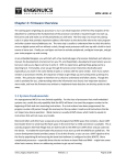
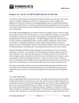
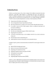
MPG LEVEL 2
Chapter 1: Hardware
The development board for this course is very much like a prototype board you might do for a product
developed in industry. The main elements are the microcontroller, LCD, and ANT radio, and the board
is supported with the user input (trackball and buttons) as well as a power supply. However, the board
also has a few extras like a UART for programming or otherwise communicating (perhaps for debugging)
and a daughter board connector for future expansion.
This chapter examines the key components to discuss why they were chosen and provide an overview of
their capabilities, then goes over the schematics to explain all of the circuits. We conclude with a look at
the PCB and discuss the important decisions made in positioning components and routing the board.
1.1 Selecting a Microcontroller
The Cortex family of microprocessor cores seems to be having an immense impact on the embedded
system industry, as evidenced by the fact that virtually every microcontroller manufacturer who has had
their own proprietary lineup of parts has added a Cortex-based lineup as well. Developers who used 8
and 16-bit micros due to their low power consumption and low cost over 32-bit parts like those based
on the ARM7 are now considering the higher power Cortex parts that compete in power consumption
and cost, yet still offer the greater capability of a 32-bit architecture running the very powerful ARM
instruction set.
Another huge advantage to an ARM core is scalability. Just as the ARM7 scaled to ARM9 and ARM11,
Cortex parts scale from M0, M1, M3, and M4. There are additional Cortex parts that scale all the way up
to application processors that run in the GHz speeds and essentially compete with Intel and PowerPC.
Figure 1.1.1 shows the ARM cores available as of June 2010.
Figure 1.1.1: ARM processor cores.
Source: http://www.arm.com/products/processors/index.php
notes_mpgl2_chapter1.docx
Version 1.1
Page 1 of 37
MPG LEVEL 2
Every designer should recognize the value of this type of scalability. As someone who is taking this
course can attest to, learning a new microcontroller takes a lot of time and effort, not to mention costs
in hardware and design tools. Moving through the ARM family allows you to reuse many of the same
skills you have already invested hundreds of hours in.
ARM has taken a step further with an attempt to provide some compatibility across vendors who are
integrating their cores. They have introduced the Cortex Microcontroller Software Interface Standard
(CMSIS) which dictates how manufacturers should build their microcontrollers around the Cortex core.
In the past, designers have to look at the header file(s) for a new processor and figure out the
conventions that are used by the manufacturer for naming registers and bits and then ensure their
firmware follows those conventions. If you made the switch to another vendor, you had to spend a fair
bit of time getting used to the new vendor’s conventions and updating all of your code to be compatible.
The magnitude of this type of inconvenience was begging for a standard, and finally CMSIS is starting to
gain traction.
For example, NXP, ST and TI (among others) all make a microcontroller based on a Cortex-M3 core.
They all include similar peripherals like UARTs and Timers and interrupts and analog to digital
converters. If they follow the CMSIS rules then the registers,
configuration and general operation of their respective
peripherals will be very much the same so that developers can
write generic code that will work on any platform. Since this is
starting to sound like an advertisement for ARM, now is a good
time to offer some criticism. First of all, not everything will be identical between processor vendors, but
as much as possible will be at least at a certain layer of the software (when it gets down to the nittygritty like register base addresses, there will probably be some processor-specific code required).
As it so happens, most of the original development for this course was completed on an STM32F103VC
Cortex-M3 part from ST Microelectronics, and then ported over to the NXP LPC175x. This provided firsthand experience with using the wonderful promises of CMSIS, and it actually did make the conversion
go fairly smoothly. Though many of the specific register names within peripherals were entirely
different, the structure of the code and the conventions for register and bit accesses were very similar.
Having taken the time to become familiar with those conventions of CMSIS allowed certain tasks to be
completed faster and even some assumptions to be made that helped speed things up. On the other
hand, there were a lot of minor differences that were just irritating. For example, the ST part uses
alphabetic characters for GPIO ports while NXP uses numerical values. The CMSIS standard for accessing
GPIO is with a pointer-to-structure-like definition like GPIOx->peripheral_register where ‘x’ is the port
name. Since ST’s GPIO port names were GPIOA, GPIOB, etc., it was correctly assumed that NXP’s GPIO
names would be GPIO0, GPIO1, etc. That made making these firmware changes relatively quick and
easy from a structure point of view, but still required some work since ST uses a “BSRR” (bit set-reset
register) while NXP uses “FIOSET” (bit-set register ).
notes_mpgl2_chapter1.docx
Version 1.1
Page 2 of 37
MPG LEVEL 2
Beyond the basics of register and bit naming, CMSIS also tries to standardize how basic processor
operations are performed. This is a reasonably well-intentioned idea, but like any application of a
standard, there tends to be some added cost in overhead. For example, CMSIS provides a universal set
of functions for setting GPIO functionality. A CMSIS purest would use these function calls to setup all
their IO, even though that could mean literally hundreds of function calls to completely set up a large
processor. The same configuration could be done by just a few hardware-specific instructions. Of
course, the code is no longer portable and definitely not “CMSIS Compliant.” As we have already
discussed, the fact that low-level drivers will still need processor-specific code also raises some doubt
about the attainability of true universality amongst vendors. Frankly, processor vendors may choose to
purposely resist CMSIS in some areas to maintain some individuality and lay claim to some sort of
superiority as a result.
In reality, a company will likely stay with a certain processor vendor unless there are very compelling
reasons to change like a special feature or an amazing price that cannot be met by any other
manufacturer. Aside from that, even changing parts in the same family will require some code
maintenance regardless of whether or not the CMSIS standard has been followed, simply because the
resources and their allocation will change along with the microcontroller selected and its application.
All that being said, using a Cortex part has many advantages regardless of the target application and
completely independent of whether a designer chooses to follow the CMSIS spec (though given the
porting experience from ST to NXP, using CMSIS conventions are definitely recommended). Cortex-M3
parts have been out for only a few years, but the traction they have gained due to their excellent overall
performance has no doubt positioned the part for success for many years to come. Choosing the
Cortex-M3 LPC175x for this course was very purposeful to ensure all the skills here are with one of the
most up-to-date and relevant microcontrollers on the market right now.
The decision on processor choice for this course came down to two vendors who had parts that were
essentially equal. The development board requires a device with the following:
1.
2.
3.
4.
5.
6.
7.
8.
UART interface for serial programming and debugging
SPI interface for ANT
I²C interface for the LCD
I²C and SPI interfaces for the Engenuics daughter board connector
GPIOs for 7 button signals, 4 LEDs
PWM output for the buzzer
A minimum of 8kB of RAM for the LCD plus at least 1kB for other processor operations
An estimated 10kB of flash memory for the program plus 10kB of flash available for LCD bitmaps
Both ST Microelectronics and NXP Semiconductors offer attractive Cortex-M3 parts that can meet the
requirements for the development board. To be consistent with MPG Level 1, the NXP part was chosen.
This allows one to leverage the familiarity in the conventions and styles of a single company in their
notes_mpgl2_chapter1.docx
Version 1.1
Page 3 of 37
MPG LEVEL 2
documentation, architecture decisions and example code. Specifically, the LPC1752 part is used as it has
64kB of Flash and 16kB of RAM – plenty for our requirements. Higher parts in the family offer a few
more features and of course more flash and RAM, but none of these are necessary for this project so we
decide to pick a lower-level part due to cost. All processors in the family are pin-for-pin compatible with
each other, so if ever a feature of a higher part was required, then it could simply be dropped onto the
board.
1.2 LPC175x Cortex-M3 Microcontroller
Familiarizing oneself with the processor pin map is a good starting point in a design. Figure 1.2.2 on the
following page shows the complete pin-out of the processor. Every possible function of every pin is
indicated and the pins are shown in the correct order, though the part is drawn with pins on only two
sides instead of on all four sides as the part is actually configured. This is a good time to remind the
reader that the schematic symbols in CAD software are just that: symbols. Their appearance and pin
positions have no bearing on how the device is actually configured. Only the pin number and the signal
attached to it are important and the user must be able to assign pins per their correct functions. The
CAD software looks only at the pin number to map the connection to the correct location on the PCB
land pattern for the part.
Information to build this symbol was taken from the processor datasheet where each pin is listed with
its name and all available options. Often the device manufacturer will show a complete symbol like
Figure 1.2.2, but with this processor they have not. An abbreviated representation of the actual pin
locations and physical positioning on the chip are shown in the processor data sheet and repeated here
in Figure 1.2.1.
Figure 1.2.1: Pin configuration for the LPC175x processor in LQFP package
Source: LPC1759_58_56_54_52_521 Product data sheet, Rev. 04 – 26 January 2010, NXP Semiconductor
Building the schematic symbol is admittedly tedious but also very, very critical to complete correctly. If
a pin is assigned incorrectly, then the entire design will be flawed along with any other design that
notes_mpgl2_chapter1.docx
Version 1.1
Page 4 of 37
MPG LEVEL 2
makes use of the symbol from the schematic library. It is therefore highly recommended that the
symbol be checked and rechecked by at least two pairs of eyes. Once the base symbol is verified,
application-specific symbols can be created where pins are moved around and grouped to best fit on the
schematic page and attach to the other circuits in the design. We will see this a little later on.
Figure 1.2.2: LPC175x Microcontroller Pin-Out Schematic Symbol
notes_mpgl2_chapter1.docx
Version 1.1
Page 5 of 37
MPG LEVEL 2
1.2.1 Pin Allocation
The next somewhat tedious task is assigning pins to the circuits in the design. The block diagram of the
device is a good tool to assist in this, and in fact can be improved at this point by adding more specific
information. Virtually every GPIO pin on the LPC175x processor has several options available for how it
can be used. For example, pin 80 is the Port 0.3 GPIO, UART0 receive data line (RXD0) or one of the
analog inputs. It is important to investigate each pin before mapping begins to determine if there are
any critical functions you need and how using different pins will impact the remaining functionality
available on the other pins. In general, the order of assignment should be something like this:
1. No-choice pins: power, ground, clocks, etc. can be hooked up first just to get them out of the
way. All power and ground pins need to be connected. It is suggested that JTAG pins for
programming / debugging fall into this category as well even though some processors allow you
to multiplex GPIOs onto these. This is a highly unadvised practice if you plan to load your device
over JTAG, or if you do any debugging. The LPC175x does not multiplex any of the programming
pins, so here you do not have to worry about it (the alternate signals shown for some of the
JTAG pins are for different types of debuggers).
2. One-of / special function pins: any signal / peripheral that you need that is available on only one
pin must be assigned first since there are no other options. If two such signals you need are
only available on one pin, then you either have to figure out if you can multiplex them somehow
(perhaps with an external mux), select a different processor, or change your design.
3. Peripheral-connected pins: these include communication ports, interrupt pins, analog pins,
PWM pins, timer/counter pins, etc. Often there are multiple choices to content with. For
example, you may only need 3 analog inputs, so pick pins that do not have other useful
functions on them. Communication ports can also be selected to ensure you get everything you
need. For example, since the LPC175x has four UARTs but only two I2C ports and since we need
two I²C ports and only one UART, it would be logical to assign the I2C pins first, then use
whatever remaining UART is available.
4. GPIO: signals that only need to be 0, 1 or Hi-Z can be allocated next. In general, it does not
matter where you put these but you should still be aware of what functions you are giving up if
you claim a pin. You must also ensure that the pin will do what you think it will do. Some
processor GPIOs will only accept inputs up to the processor supply rail which may be an issue if
you run a 3.3V rail but talk to another device with a 5V rail. Or, some pins might have opencollector drivers instead of push-pull drivers. GPIO assignment should also be influenced by
firmware. For example, if you wanted to show an 8-bit counter on LEDs, then the LEDs should
be assigned to consecutive pins on the same port if possible. This will help when writing code
because the LED driver can write to consecutive bits in a single register to turn the lights on and
off. If you randomly assign LEDs to pins all over the place, then it will require a bit more code to
notes_mpgl2_chapter1.docx
Version 1.1
Page 6 of 37
MPG LEVEL 2
map those and update the LEDs when required. Though a lot of times this cannot be avoided,
any consideration and optimization will likely lead to a better product delivered in less time.
5. Unused pins: many designs will not need all the processor pins available. In this case, be sure to
consult the processor data sheet to ensure you do the right thing with these unused pins. You
may be able to leave them floating, or you might want to tie them high or low directly or
through a resistor. If you have the space, it is highly recommended that you stick a test point on
them so they are accessible should you decide to add something to the board or make a
mistake. Almost all development boards would take the test point approach to maximize
flexibility. If you are really unsure what to do with them, add both a pull-up and pull-down
resistor in addition to the test point. Then you have all options available and the only cost is
board space.
Given all that information, we will allocate pins and peripherals as follows:
1.
2.
3.
4.
5.
6.
LCD communication: I²C1 and Port 1 GPIO.
ANT communication: SSP0 and Port 1 GPIO.
UART ISP / serial debug port: UART0.
Trackball / button inputs: Port 2 interruptible GPIO.
Daughter board: I²C2, SSP1, UART3 and Port 2 interruptible GPIO.
Remaining GPIO as required and all power, ground and clocks.
The way this was all done was not at all arbitrary – the steps described above were taken exactly. First,
the entire ”Pinning Information“ section of the datasheet was read to see if any particular pins had
critical functions that must be used. Note that you need to be very careful when looking at datasheets
that cover entire families of parts. To use this processor, we have two documents: a Product data sheet
and a Product User manual. In this case, the “Product data sheet” covers only the LPC175x family that
are all 80-pin devices. The “User Manual” covers the LPC17xx family (175x and 176x parts), which
includes 100-pin devices. Therefore, the User Manual pin mapping has a pair of extra columns that
differentiate the pin purpose on the 80-pin and 100-pin parts. Obviously the 80-pin package does not
have all the signals that the 100-pin package has.
Since this design has relatively few requirements and the processor itself does not allocate too many
similar functions per pin, assigning pins was quite simple. In fact, the only pins that stood out from
reading the pin map were those related to serial programming the device. Pin 41 is the signal used to
enter boot loader mode after reset, and UART0 TXD0 and RXD0 are the communication lines over which
the boot loader communicates. This is critical for using the serial programmer. Pin 41 is also shared
with the external interrupt pin, EINT0. This investigation led to something that required specific
attention: the external interrupt pins.
notes_mpgl2_chapter1.docx
Version 1.1
Page 7 of 37
MPG LEVEL 2
1.2.1.1 External Interrupt Pins
On the LPC214x processor used in MPG Level 1, only 4 GPIOs could be configured as external interrupt
sources (EINT0 – EINT3). The four buttons on that development board were therefore connected to
those lines. On the LPC17xx family, the same EINT pins exist, however the processor datasheet says that
all GPIO pins on Port 0 and Port 2 can be used as edge-sensitive interrupt sources. This is a good thing
since we want all 7 of our button input signals to be on interruptible inputs. It is doubly good because
the 80-pin package of the 175x series only offers EINT0. Though that does not sound like a very
significant conclusion, it actually is and took a fair amount of time to understand. Investigation into all
of it went like this:
1. Find the statement in the data sheet that confirms Port 0 and Port 2 are interruptible GPIOs.
2. Look at the Nested Vectored Interrupt Controller (NVIC) section of the data sheet to read what it
says about external interrupt sources: the information about the GPIOs is repeated, so no
additional help there.
3. Look at the NVIC section of the processor user manual. In Table 50: Connection of interrupt
sources to the Vectored Interrupt Controller, see the note, “EINT3 channel is shared with GPIO
interrupts.” No other information is found in the NVIC section.
4. Move to Chapter 9: GPIO in the User manual. Note reference to interrupts in “Basic
Configuration.” In section 9.2.2, there is discussion of the generated interrupts. Since all pins
on Port 0 and Port 2 share the same (single) NVIC line, it implies there will be a register to
enable / disable particular port pins as being interrupt sources. The interrupt service routine
(ISR) that handles this single interrupt source of the NVIC will therefore have to parse the
different input signals to determine which caused the interrupt, then branch to the particular
function to handle that interrupt. It also implies that a level of priority will be required in the
event that simultaneous buttons are pressed.
5. Find table 9-101: GPIO interrupt register map. Here are the registers where individual pins can
be set to provide rising and/or falling edge-triggered interrupts (the IntXEnR and IntXEnF
registers, where X is 0 for Port 0 and 2 for Port 2). The status registers are also here (IntXStatR
and IntXStatF) – these will hold the bits that the ISR will poll to see which interrupt occurred.
6. Discover that EINT3 is not physically present on the 80-pin parts. Therefore we do not have to
worry about that input signal, and can just enable Port 0 and Port 2 interrupts as required.
With this information confirmed, we can safely allocate all the buttons to any pins on Port 0 or Port 2 as
we please, making this allocation less critical which could have caused conflicts with some of the
communication peripherals that are also on Ports 0 and 2.
notes_mpgl2_chapter1.docx
Version 1.1
Page 8 of 37
MPG LEVEL 2
The next step in selecting pins was to print a copy of the schematic symbol in Figure 1.2.2 and write in
any of the critical pins required. On this printout, any multiplexed function that was not needed for sure
was crossed off to help narrow our selections down and make the picture clearer. Following the
selection hierarchy, critical pins and no-choice pins were identified on the sheet.
The UART selection was made next. Notice that only UART1 is a fully-defined UART with the hardware
flow control lines Ring, DCD, DTR and DSR. However, we know from reading the pin documentation that
UART0 must be used for the boot loader. At this point an important decision is made: should both
UARTs be made accessible on DB9 connectors so that programming can occur on UART0 and a full UART
can be provided through UART1; or does cost, space and functionality requirements override the need
to make UART 1 accessible. The latter argument wins out, but as a consolation, the additional UART pins
will be brought out to test points near the connector so it would be possible to tie in to the signals.
1.2.1.2 Pins with Multiple Connections
Note that UART1 (and a few other peripherals) have signals that appear on several different pins. It took
a bit of hunting to see how this was handled, but eventually the information was found in the product
manual on page 103 (see excerpt below). Given this information, the UART pins were selected based on
the two options available (Port 0 and Port 2). Port 2 was selected because none of the UART functions
on those pins overlapped pins of other communication peripherals. With this selection made, the
alternate UART1 pins can be crossed off since they are not needed anymore.
For the SPI interface, the LPC175x family offers a single SPI peripheral, or two SSP peripherals. The
dedicated SPI peripheral is a legacy device that is limited in functionality over an SSP peripheral. For our
purposes, they function the same but we will implement our ANT SPI communication assuming the SSP
peripheral. Since the pins are the same, it does not really matter. Since the UART1 functions of the pins
where the SSP0 is attached have been crossed out, these were assigned next.
Some of the other signals on the processor symbol could be selected next since they have only one
peripheral option left, though we had to be careful to avoid taking Port 0 or Port 2 signals that are
possible interrupt sources needed for the 7 buttons. The buzzer is assigned to P1.18 since it is a PWM
output that has no other required multiplexed signal. P4.28 and P4.29 are not used for anything else so
notes_mpgl2_chapter1.docx
Version 1.1
Page 9 of 37
MPG LEVEL 2
they can be set to use UART3 for the daughter board connection. The remaining SSP pins for the
daughter board are allocated. P1.0, P1.1, P1.4, P1.8 are set for LEDs and P1.9, P1.10, P1.15 are chosen
for the LCD backlight control, LCD reset line and LCD chip enable line, respectively.
The I²C busses are allocated somewhat arbitrarily: I²C1 is chosen for the LCD, while I²C2 will be for the
daughter board. There were no other factors that contributed to selecting one over the other. The only
consideration was to share an I²C bus with the LCD and daughter board. Since the LCD bus will be fairly
busy and since we have plenty of pins available and a spare I²C peripheral, it makes the most sense to
allocate one each to the LCD and daughter board.
The remaining Port 0 pins are taken up with the seven button inputs. Though it would be nice for
routing purposes to use P2.8 and P2.9 for the ANT_PWR and ANT_RESET signals, these are the only two
remaining interruptible GPIO, so they are assigned to the daughter board. There are also four other
GPIO ANT signals required that do not have any special needs, so choose the group P1.22 – P1.25 for
them all.
All leftover pins are unused. We will loosely allocate P1.30 and P1.31 as analog pins since they are the
only remaining analog GPIOs. These and the rest of the digital pins will be given test points for future
use.
This entire exercise took about 3 hours to complete. Indeed it is a tedious task but obviously very
important (just as tedious and important as getting the processor schematic symbol correct in the first
place). For the sake of completeness, a scanned image of the symbol “worksheet” is shown in Figure
1.2.1.2.1 to show how truly a pen-and-paper exercise this is. The solid black-outs were done first for
functions that were not needed for sure. The x-outs were done as it became clear that that particular
pin function was not needed or not used. Circled pins are the functionality that must be assigned when
we get to that part of the firmware. The notations on each pin indicate the target signal for the selected
function. Note that every pin has been assigned, even if it is just to a test point as indicated by a small
square.
notes_mpgl2_chapter1.docx
Version 1.1
Page 10 of 37
MPG LEVEL 2
Figure 1.2.1.2.1: Scan of completed pin mapping symbol worksheet
Now that all of the pin assignments are complete, a device-specific processor schematic symbol can be
made that does not need to show all of the unused pin options and organizes the pin-out in a way that
will facilitate an orderly schematic. With that complete, the remaining hardware design and schematic
capture can take place.
notes_mpgl2_chapter1.docx
Version 1.1
Page 11 of 37
MPG LEVEL 2
1.3 Development Board Schematic Review
Even if you never design a circuit in your life, having a basic understanding of the hardware platform on
which your firmware will run is invaluable if not essential. Not only do you learn about the choices and
tradeoffs made in designing the circuits in the system, you also have an opportunity to contribute
feedback through intelligent discussion. There is always an inherent rift between “the hardware team”
and “the firmware team” who tend to blame the other when things go wrong. If you get to play both
roles, then the only one you can blame is yourself. Even if doing both is not your full time job, having
knowledge and experience with both allows you to quickly understand why both teams must contribute
and ultimately make sacrifices to help each other out to successfully build a working product.
At the beginning design stage of any product, both hardware and firmware teams should meet to
discuss the project’s requirements, processor selection and planned approach for module
communication and resource use. As soon as possible, the firmware team should supply an overview of
their high-level design to hardware, and hardware should provide a block diagram or draft schematics.
Final schematics should be reviewed and discussed, at which time the firmware team hopefully has a
clear view of how their code will use the hardware. This is also a good time to share and clarify any
assumptions made, such as how particular circuits are used, what the expected processor on-time is for
power consumption, etc.
Playing both sides of the equation, the MPG Level 2 processor resources were allocated and the
hardware design was completed. The course development board is broken up into five schematic pages
(the full schematic package is available on the MPG website) that cover the following:
1.
2.
3.
4.
5.
Block diagram
Power supply
Processor
ANT Radio
User I/O
Each circuit block will be discussed in detail to ensure a full understanding of the components and
connections chosen for this design. The process of selecting the components is not entirely described
here, though the general steps for everything can be summarized by the following:
1. Requirements definition for each circuit.
2. Part selection and evaluation based on previous experience, reference designs and/or new
research and investigation.
3. Analysis, prototyping and testing as required (particularly for power supplies).
4. Schematic symbol creation (if parts are not already in your design library).
5. Schematic capture of the circuit.
notes_mpgl2_chapter1.docx
Version 1.1
Page 12 of 37
MPG LEVEL 2
Clearly this is one of the very handy advantages of working on a design that is already complete – many
hours of work go into designing a product and correctly integrating the various circuits for the design.
The sections discuss the final circuits chosen, but do not attempt to describe much of the decision
making that led to the final selections.
1.3.1 Block Diagram
Schematics can be captured entirely on a single page but can become cluttered quite quickly. The main
advantage is that every circuit is available without flipping pages, and it can be easier to view and
understand interconnections. There is also potential to reduce some errors that may arise from
improperly naming signals lines between pages – many of these can be caught by the design tools, but
some can squeak through.
For multi-page schematics, a block diagram is used to show the interconnections between all the
schematic pages (see Figure 1.3.1.1). Though this is not required by the design tools, it can help to
ensure that every signal goes somewhere and can assist in identifying errors in defining the data
directions of the lines.
Figure 1.3.1.1: Schematic Block Diagram
notes_mpgl2_chapter1.docx
Version 1.1
Page 13 of 37
MPG LEVEL 2
The page symbols are automatically generated by the design tools though they have to be adjusted and
resized to make all the connections between each page line up. Signal lines can be drawn between all
the ports to explicitly show the connection, but this is another optional step as long as the project
environment is configured to automatically connect like-named ports.
A block diagram page is also a good spot to put non-electrical component symbols on and other design
notations that are relevant. In this case, the PCB label is shown along with two fiducial markings that
are used as reference locations for SMT PCB population. Both the label and the fiducials have
corresponding PCB land patterns that will appear on the PCB.
1.3.2 Power Supply
The essence of any good design is a quality, stable power supply. The first challenge of a power supply
design is getting a simple circuit to operate properly over the lowest, nominal and peak loads that the
supply is expected to source. With a linear regulator, this is generally easy. With a switching power
supply, it is much more difficult especially if noise and board space are concerns.
The MPG Level 2 design (see Figure 1.3.2.1) leverages the same proven supply from the development
board used in MPG Level 1 and provides 5V and 3.3V rails. The switcher is highly robust and supports a
wide voltage input range anywhere from 7 to 30V. The relatively low switching frequency bodes well for
avoiding RF interference or any other interference with MHz-frequencies on the device. Large
capacitors are used to provide ample current sourcing for transient response and stability, and a large
inductor is used to store plenty of energy. The power supply is also quite reasonably priced given the
components it requires.
Figure 1.3.2.1: MPG Level 2 development board power supply
notes_mpgl2_chapter1.docx
Version 1.1
Page 14 of 37
MPG LEVEL 2
The power supply has a “TVS” (transient voltage suppressor) clamping diode (D2) on the 5V output to
deal with any input transients that were found to appear with certain transformers that power the
board. There is also a fuse (F1) to help those with not-so-great soldering techniques from destroying
parts on their boards through ground shorts. On that note, prior to applying any power to the board,
do a continuity check from the 5V test point to ground and from the Vcc test point to ground to check
for shorts.
This design also “dual-footprints” the input and output capacitors so either thru-hole or SMT parts can
be used. This is a matter of pricing and availability more than design performance. The LDO was chosen
as it has a common footprint across several vendors and the adjustable output can address any changing
supply needs down the road.
A DC wall wart or a 9V battery is used to power the board. The J-Link power supply can also directly
power the 5V rail and is diode-protected so you can safely plug the J-Link into the board when the board
is powered externally. Because of the diode, the actual 5V voltage will be around 4.5V when powered
from a J-Link. D1 and D12 protect their respective power sources from back charging.
All LEDs in this design have been set with 1.2k resistors even though 1k is a more standard part for
current-limiting an LED. However, since the feedback network R4 / R6 of the power supply needs a 1.2k
resistor to properly set the output voltage, inventory from having both 1k and 1.2k resistors in the
design can be saved. As far as the LED is concerned, 1.2k or 1.0k really makes no difference. If you have
other resistors lying around and want the LEDs brighter or dimmer, you are free to populate the LED
resistors with any value as long as a maximum 10mA of current is not exceeded.
Lastly, test points at all the critical locations are available.
1.3.3 Processor
Figure 1.3.3.1 shows the board-specific LPC175x schematic symbol and all the connections required to
make the device perform its duties. The symbol is the simplified version of the first symbol you saw in
Figure 1.2.2. Any pin function that is not needed is no longer shown, and pins have been grouped to
make the schematic look as orderly as possible. Note also that the pin numbers are not in any order –
the physical characteristics of a schematic symbol have no bearing on how the design tools map the
signals to the PCB land pattern. Mapping is based solely on the pin number as it matches to the pin
number on the land.
notes_mpgl2_chapter1.docx
Version 1.1
Page 15 of 37
MPG LEVEL 2
Figure 1.3.3.1: Main processor and connections
Signal names are appropriately descriptive just like naming variables in software. The names shown
here will be used verbatim in the firmware to help support consistency.
Following the schematic around clockwise from the top right, the JTAG connector is the first thing you
see. The pin out is the same for Cortex-M3 as it is for ARM7, though the documentation for supporting
components (i.e. pull-up or pull-down resistors) is better. The LPC175x includes internal pull-ups/downs
so no external parts are used. The Cortex-M3 core does not use the RTCK or DBDRQ JTAG signals so
they are tied low. The system reset line ties into the processor’s reset input on pin 14 (this connection is
made because the signal lines are both named MCU_RESET so the schematic compiler knows to make a
connection). Lastly, the DBGACK line which is specified on the J-Link devices as 5V power is attached to
the +5V rail through a protection diode so the board can be safely powered from the J-Link. The diode
prevents current flowing back into the J-Link if the board is powered externally by a higher voltage.
notes_mpgl2_chapter1.docx
Version 1.1
Page 16 of 37
MPG LEVEL 2
Figure 1.3.3.2: ANT-processor connections
The ANT connections come next. There are four SPI signal lines that are normally directly connected to
the corresponding SPI peripheral lines on the processor. During prototyping of the course development
board, it was realized that the ANT_SSP0_CS signal line driven from ANT does not work because ANT
releases the line during the last byte of a transmission which immediately shuts down the SSP
peripheral. Therefore, the signal is brought in on a regular GPIO (P0.22) and then an additional GPIO is
used to drive the actual SSEL0 line. A few fingers can be pointed at ANT or the NXP SSP peripheral
design here, but at least there is a workaround even though it costs two extra GPIO pins.
The SPI data signals are push-pull drivers and do not require any resistors to pull signal levels high or
low. In addition to the four SPI lines, four GPIOs are connected (power and reset control, and two flow
control lines SRDY and MSGRDY) to provide the other outputs to ANT. The note on the schematic
reminds anyone looking at the design that the ANT module is the SPI master device and the LPC175x is
the slave. The “MOSI” (Master-out-Slave-in) and “MISO” (Master-in-Slave-out) naming convention is
used to avoid very painful mix-ups of the communication lines.
Next are the LCD connections. The I²C bus requires pull-up resistors on both the clock and data lines
since all I²C devices are connected with “open-drain” IOs. This is because both the master and slave(s)
need to be able to drive the signals low and avoid shorting power and ground when one device wants to
drive a line high while the other wants to drive it low. The standard value of these resistors is 10k, but
can (or must) be increased depending on the bus characteristics. Several factors can exist that make a
case for using smaller (stronger) pull-ups:
1. The number of devices connected to the bus – more devices mean more capacitive load on the
bus lines
2. The physical distance between all of the devices – longer traces have more parasitic capacitance
and higher resistive loss
3. Bus speed – running the bus at 400 kHz vs. 100 kHz requires faster rise and fall times.
It is easy (and a very good idea) to use an oscilloscope to look at the clock and data lines of the I²C bus
once the circuit is populated and running. The signals should ideally be very good square waves. If the
notes_mpgl2_chapter1.docx
Version 1.1
Page 17 of 37
MPG LEVEL 2
rise times are rounded, they are too slow and the pull-ups should be stronger. If the fall times are too
rounded, then the pull-ups are too strong and should be reduced. Values of 3.6k were chosen because
the bus runs at 400 kHz, and though communication worked with 10k parts, the signals looked better
with 3.6k pull-ups. 3.6k was picked specifically because the part is used elsewhere in the design.
The remaining LCD connections are three output lines to control the LCD backlight, reset and chip select
signals. Though any or all of these lines could be tied appropriately high / low at the LCD, having control
is important in the case of the reset line, nice to have in the case of the LCD backlight, and safe to have
in the case of the CSB line. Since IOs are in ample supply here, allowing the MCU to have control is a nobrainer.
The UART0 lines are the next group of pins. TXD0 and RXD0 are attached to the RS-232 line-driver, so
they will be 0/3.3V signals at the LPC1752. When the UART is connected to a PC, all the lines operate at
the +/-12V PC levels which is automatically taken care of by the transceiver IC. The signals are driven
with push-pull drivers so no pull-up/down resistors are required. The most confusing part about
hooking up UART lines is deciding if the processor’s transmit line (TXD0) should attach to pin 2 or pin 3
of the DB9 connector. Technically, pin 2 on a DB9 connector is designated RX and pin 3 is designated TX
– this is from the perspective of the PC. In this case, TXD0 (POMI) should end up going to pin 2 and
RXD0 should end up on pin 3 of the DB9. This assumes that a “straight-thru” serial cable connects the
PC and development board. If a “null-modem” serial cable is to be used, then the cable swaps pin 2 and
3. Likely one of the most irritating and time-consuming exercises for an embedded designer is not
realizing they have a null-modem cable and troubleshooting why their serial communication is not
working. The worst part is that most serial cables are not marked if they are straight-thru or nullmodem, so you have to buzz them out with a multimeter to figure it out. It is a great idea to label all
your serial cables!
The Engenuics Daughter Board connector allows an array of different devices to attach to the
development board. Several I²C devices can be daisy-chained and other SPI and UART devices can also
be added. Two digital/analog pins are also included, and any combination of all the pins could be set as
GPIO as required. Having such a connector allows for virtually unlimited capability for experimentation
based on the main development board. Perhaps the most relevant right now would be either a different
LCD (like a full-color device) and perhaps an external data flash to store more images, fonts, etc. This
connector will be standard on all Engenuics development boards. Various daughter boards are already
in design – check out http://www.engenuics.com/products_developmentboards.php#extension
Continuing with the schematic examination, the bottom part of the symbol has all of the processor
ground connections. There are discrete pins for the analog ground (VSSA) and a reference voltage
ground (VREFN) that could be routed separately to minimize electrical noise in these circuits. This is not
a concern in this design, so they are simply lumped together with the other ground pins. Ideally,
multiple ground connections like this will connect to a solid ground plane layer to minimize “ground
loops” that can result from small trace impedances. A solid copper layer minimizes impedance and thus
notes_mpgl2_chapter1.docx
Version 1.1
Page 18 of 37
MPG LEVEL 2
minimizes ground loops. Problems like this would never be noticed for this development board, but can
cause trouble with EMI (electromagnetic interference) and performance for highly-sensitive analog
applications.
Figure 1.3.3.3: Bottom portion of processor schematic page
Crystal oscillators come next. The main crystal for this board will be 12MHz. Originally, a 4MHz crystal
was selected as they can be purchased in larger packages that happen to be relatively inexpensive.
4MHz is the slowest MHz-frequency crystal that you can buy reliably and would be fast enough for any
task on the PCB while providing the lowest power consumption (faster speed = more power
consumption). The LPC175x has a PLL (phase lock loop) that can up-convert the oscillator frequency to
any speed desired (up to the device’s maximum) but it cannot down convert to a slower speed. As it
turned out, the 12MHz crystal used in MPG Level 1 was almost the same cost and much, much smaller
so it was chosen in the end.
A footprint (land pattern) for a crystal to the real-time clock (RTC) input is provided but not intended for
population on this board. Since the pins cannot be used for anything else, adding the land patterns
makes sense. If you wanted to use the RTC functionality, you could simply populate these parts.
Both crystals are shown with “guard rings” that are implemented as PCB traces around the pins and the
crystal. This is a matter of good EMI and RF (radio frequency) design practice. The impact
(improvement) of guard rings is debatable, but since they are free and – probably at least once in history
–have shown to reduce noise that may appear in the circuit, they are included. Noting this on the
schematic directs the person doing the PCB layout to add them explicitly.
Above the crystals are all the GPIOs that are fairly uninteresting on this page of the schematic. The
unused pins each have their own test point. The test point names match the pin name for easy
reference. LED outputs sit above the unused lines. The seven button inputs are next above, followed by
the buzzer output. Note that all signal names are descriptive though kept as short as possible.
notes_mpgl2_chapter1.docx
Version 1.1
Page 19 of 37
MPG LEVEL 2
Figure 1.3.3.4: Reset and BOOTLOAD signals
P2.10 is the boot load signal. The datasheet states that the signal is active-low and has a built-in pull-up.
This line can be pulled low to engage the boot loader firmware on reset by flipping the first dip switch
(see schematic Sheet4).
As for the reset line, there are three possible sources of reset. The first source is from the J-Link which
comes over as MCU_RESET from the JTAG connector. The user is provided a button for manual reset –
an essential for any design. The third source is from the aforementioned Flash Magic ISP capability.
When connecting multiple driving sources to a line, one must be sure that the signals will cooperate. If
you try to connect multiple push-pull drivers and one happens to be driving low while the other is
driving high, you will likely have some brown-out problems. The LPC’s reset line has an internal pull-up,
but a just-in-case external pull-up resistor was added as well. Pads are essentially free, board spins are
not.
The last part of this schematic page is the power input to the processor. You will find a bank of
decoupling capacitors at the top left of the page, one for each VDD pin as prescribed by good design
practices. Decoupling caps are always placed as close to the IC’s power pins as possible to try to make
the last element that the pin sees a capacitor. This keeps the supply voltage steady during transients
since voltage does not change instantaneously on a cap. Without decoupling caps, the pin sees an
inductance and resistance from the signal trace which can result in voltage transients that can lead to
nasty behavior since even very fast droops in voltage can impact memory in the device. That being said,
for a design like this board running at the relatively slow speed and populated on a fairly small PCB, you
could likely remove all the decoupling capacitors and still operate without a problem.
notes_mpgl2_chapter1.docx
Version 1.1
Page 20 of 37
MPG LEVEL 2
1.3.4 ANT AP2 Radio
The ANT radio schematic is one of the more fun pages on the design since it incorporates mysterious RF
technology. The circuit is quite similar to that found on the MPG Level 1 development board but has a
fundamental difference. For MPG Level 2, ANT communication will use the synchronous method of
communication (SPI) rather than the asynchronous UART. See Figure 1.3.4.1.
Figure 1.3.4.1: ANT AP2 schematic page
Though Dynastream does not explicitly recommend using SPI instead of UART, most of their reference
designs choose SPI and verbally they seem to lean towards it. From experience with devices using both
methods, SPI mode is highly recommended. Though both modes work well, SPI has better flow control
between the master and slave that help to manage message passing more easily. Much faster
communication data rates can also be achieved, and of course there is the added benefit of clock-speed
independence since SPI is synchronous and the clock is transmitted with the message. Dynastream does
notes_mpgl2_chapter1.docx
Version 1.1
Page 21 of 37
MPG LEVEL 2
recommend SPI to achieve the lowest power operation of an ANT-based system. The downside is that
implementing SPI might be considered marginally more complicated especially if you do not have an SPI
slave peripheral and have to bit-bash the messages. It also requires one additional I/O line – a negligible
consideration for this development board (though as we discussed earlier, because of the SSP peripheral
operation, a further two GPIO signals are required).
To implement SPI (byte mode vs. bit mode since we will be communicating with an SPI peripheral), the
“Interfacing with ant general purpose chipsets and modules” document from Dynastream instructs you
to configure the device with PORTSEL high and the BR lines low. The AP2 data sheet also suggests tying
UART_RX high and leaving UART_TX floating. For an RF device, it is highly recommended to follow every
manufacturer’s suggestions!
There are two crystal sources for the AP2, both of which have guard rings for the same reasons that the
processor crystals have guard rings. The 16MHz crystal is mandatory as it provides the baseband
frequency for the radio. It is very important to route this crystal properly and correctly calculate the
external capacitors to provide the crystal load capacitance. The 32k crystal is optional. The AP2 can
derive a 32k clock from the 16MHz signal, though this takes slightly more power. The sleep current of
the AP2 is roughly 2uA when the 32k crystal is present vs. 100uA when the device sleeps with the
16MHz oscillator active. The difference in power consumption is negligible for this design, but for an
extremely low power device the 32k crystal is essential. 2uA vs. 100uA might not seem like a lot, but for
a device that sleeps most of the time and runs on a coin cell battery, a factor of 50 for current
consumption is the difference between operating for two weeks vs. two years! Though the rest of the
MPG Level 2 development board is not designed with ultra-low power in mind, you could still
experiment with just the ANT radio to reduce its power consumption, thus the footprint is provided (but
the parts will remain unpopulated). To tell the AP2 that no 32k crystal is present, a 0R resistor is placed
at C28 to tie the line low as recommended by the ANT documentation.
The magical PCB antenna and “balun” (balanced – unbalanced matching circuit) comes directly from the
Nordic / Dynastream reference design and is essentially identical to the MPG Level 1 AP2 development
board. The balancing part of the “balun” takes the dual radio feed ANT1 / ANT2 and couples it to a
single feed going in to L2. L2, C29, C30 then convert the signal impedance to 50 Ohm to match the
antenna. When the entire system is designed and matched correctly, the performance of the radio is
optimized. This comes from the same principle in DC where it is known that for maximum power
transfer, the source impedance should match the load impedance. More details on the RF magic here
would need to come from an RF engineer.
The PCB antenna is called an “IFA” (Inverted F Antenna) for reasons that should be obvious when you
look at the PCB. From a DC perspective, the antenna is indeed a short to ground. C29 ensures that no
DC voltage is present. From an RF perspective, the antenna is a complex circuit that successfully
receives and radiates energy. An IFA is a monopole antenna and requires a ground plane as large as
possible under it. The length of the antenna from the ground point to the tip is set at 1/4 wavelength of
notes_mpgl2_chapter1.docx
Version 1.1
Page 22 of 37
MPG LEVEL 2
2.45GHz. The distance of the feed stub from the ground feed is critical in making the antenna
impedance 50 Ohms to which the circuit is matched. The design for the antenna is taken directly from
the Nordic Semiconductor reference design.
On this development board, the length has been extended slightly to achieve better performance at the
center of the 2.4GHz ISM band as some testing on large boards in similar configurations proved
beneficial.
The power supply and remaining circuits on the ANT schematic are mostly from the reference designs.
Two GPIO lines from the processor have been added: ANT_PWR_EN allows power to be switched off to
the AP2 entirely; ANT_RESET can toggle the AP2’s reset line to make it reset via hardware (a firmware
reset command is also available). These signals were added to allow full control over power to the ANT
device and give optional “hail-marry” reset capability to the development board firmware. Note that to
actually get zero-voltage to the ANT chip, not only must the power line be turned off but all of the GPIO
lines must also be set as output low on the LPC1752. If not, then the AP2 will remain powered through
the IO lines even though it will not really be able to function since its main supply rail is not being
powered. It will draw current, though and perhaps do strange things.
1.3.5 User IO
The last schematic page captures all of the development board user IO (see Figure 1.3.5.1 on the next
page).
Starting in the top left are the four LEDs. The blue LED requires a transistor driver as typical forward
voltage for a blue LED is higher than 3V so it is powered from the 5V rail. Driving the digital NPN Q4 like
this keeps the LED active-high. The LCD backlight (LED_LCD_BL) is next, where the backlight LED is
accessed via a connector attached to the board (J7). The backlight LED is also driven with an NPN as the
LCD data sheet states that its average current is 45mA which is beyond the driving capability of the
processor pin. A 150R resistor is installed to safely limit current while still providing good brightness.
The LCD connection itself is directly from the data sheet.
notes_mpgl2_chapter1.docx
Version 1.1
Page 23 of 37
MPG LEVEL 2
Figure 1.3.5.1: User I/O
Probably the most interesting circuit on this schematic is the trackball circuit. The little trackball – the
same one you can find in the original BlackBerry devices – is an ingenious mechanical device. Figure
1.3.5.2 shows the top and bottom blow-up of the device.
Figure 1.3.5.2: Trackball bottom (left) and top (right) image
Image Source: Sparkfun Electronics
notes_mpgl2_chapter1.docx
Version 1.1
Page 24 of 37
MPG LEVEL 2
There is nothing electrical involved in this device. When you roll the ball with your finger, the four small
wheels rotate. Only one wheel rotates if you rotate exactly in the plane of either the x or y-axis. If you
are rotating across the axis, then two of the wheels will be rotating. No matter what you do, you can
never get both wheels in the same axis to turn at the same time. This is the most magical part of the
device. Somehow they have designed and built the trackball so that the subtle pressure of your finger
pushing to rotate the ball in one direction on an axis is enough to engage one of the wheels and
disengage the other. All in all you have four input signals, one each for up, down, left and right. One
thing that was learned when first working with this device is that the mechanics are very sensitive, and
any attempt to make a solder connection to any part of the device destroyed it. This is why the trackball
is glued to the PCB and not soldered in any way.
To capture the motion electrically, a Hall Effect sensor is placed on the circuit board under each of the
wheels. There are a few tiny Hall Effect sensors that do the trick, and the one chosen for the course
board is from Panasonic, AN48841B.
Creating the schematic symbol and PCB land pattern for the whole trackball circuit was a tad tricky
because the manufacturer does not provide a datasheet. The center button was first tried in a way that
relied on the conductive actuator to close a circuit on the board with the outside metal of the switch as
a ground. As just pointed out however, attempting to solder to the trackball destroyed it.
Therefore, a small, ultra-low profile switch was specified to be placed underneath the trackball. The
button on this switch is actuated by the trackball. The schematic symbol and PCB land patter are shown
in Figure 1.3.5.3.
notes_mpgl2_chapter1.docx
Version 1.1
Page 25 of 37
MPG LEVEL 2
Figure 1.3.5.3: Trackball schematic symbol and land pattern
The PCB footprint for the trackball itself (S4) is the left pattern. This symbol is placed on the board, then
each of the four Hall Effect switch lands (S7, S8, S9, S10) were placed inside S4’s guidelines. The center
button (S6) was also placed inside S4 and just barely fit and required 45° rotation. The vacant guidelines
are large enough for the plastic pegs on the trackball to fit inside, and the silkscreen will act as a wall to
contain the glue necessary to secure the trackball in place. Obviously all the switches that reside under
the trackball need to be populated before the trackball is glued on.
The other buttons and buzzer circuit are next with nothing particularly interesting to note. Both buttons
are active low and rely on the processor’s internal pull-up resistors . The buzzer can be switched on and
off with the fourth dip switch.
Figure 1.3.5.4: RS-232 converter circuit and dip switch
The last circuit provides the level translation for the UART connection to RS-232. The charge-pump /
inverter IC (U5) translates the device 0-3V signal rails to +/-5V levels for the PC. Translation is done only
for the Tx and Rx signal pins as these are the only required signals. All of the RS-232 signaling lines are
optionally available through test points to enable experimenting with full flow control. For example, a
second development board could be connected directly to the DB9 connector. If a PC was connected,
notes_mpgl2_chapter1.docx
Version 1.1
Page 26 of 37
MPG LEVEL 2
then level translation would also be required on the other lines. An example of the type of circuit
required to step down the voltage is shown for the RTS and DTR lines. These circuits allow Flash Magic
to control the BOOTLOAD and MCU_RESET lines of the processor so you do not have to manually set
jumpers to program over UART, though you do have to apply them by flipping the dip switches on where
they are connected. Figure 1.3.5.5 is a screen shot of the Advanced Options area in Flash Magic that
shows where this option is available.
Figure 1.3.5.5: Flash Magic Advanced Options settings for RS-232 control of ISP lines
Due to the lack of use of this feature, the components to clamp and rectify the +/- signal from the PC will
not be populated on the board due to cost. The NNP parts could be placed at any time if the automatic
functionality was desired.
1.4 PCB Layout
Before even a single component is placed, a PCB designer must consider the needs of a device and
balance those against parameters such as board size, cost and manufacturability. On the performance
side of things, there are key aspects to consider for all PCBs including power and ground distribution,
high-speed signal routing and potential issues with PCB capacitance, signal coupling / noise, and
impedance. When a radio is involved, board design is very important as component positioning, trace
length, ground planes and other factors must be managed since they can drastically impact how well the
device operates.
The need for performance is generally traded off with mechanical and physical needs. With a
protoboard, you often have the luxury of a few more degrees of freedom. Cost is rarely a major driver,
and mechanical constraints may be reduced or entirely removed in the very early phases. For example,
a designer might want to try several different power supply circuits, so the power section of the PCB
might be three-times larger than it would normally be with optional circuits for each supply to test. The
whole PCB might have almost-duplicate circuits for testing, or at least some circuits might have
notes_mpgl2_chapter1.docx
Version 1.1
Page 27 of 37
MPG LEVEL 2
additional components in place for configuration options or be over-designed to optimize performance.
Capacitors are often added in excess on prototypes just in case there is power supply or noise problems.
Once a prototype PCB has been manufactured, populated and tested successfully (albeit with a few
barnacle wires or hacked-in parts), the first form-factor PCB is created that is hopefully good for
production. First revision boards may still contain a few extra components unless spacing requirements
prevent it. They may also have extra test points that can allow relatively easy modification to circuits
that could still have problems. If the board has no errors, then it can be used for a production run and
extra parts are not populated. The extra land patterns could be removed entirely on future board spins.
For this development board, many of the circuits are from already-proven designs. The microcontroller
is the biggest risk as it is new to the design. Extra attention was paid in assigning pins and verifying that
they could be configured to provide the functionality needed. The overall level of risk is not particularly
high. If the PCB was to be taken to a manufacturable device with a plastic shell, size constraints, and
regulatory requirements (FCC for power supply and the radio), then mechanical design and more
attention to RF performance would be made. RF boards generally perform much better with four or six
layers so several ground planes can be used, especially when the form-factor is shrunk and there is less
room for routing (it is very difficult to rout a PCB on two layers and still create a sizeable ground plane
for the required radio performance). The development board is routed on two layers as it is large
enough to route all the signals and the ANT RF section has enough space to route properly and supply
sufficient ground plane for the antenna. Note that all components (other than the JTAG connector) are
populated on the top layer only. This is for manufacturability so when the boards are machinepopulated all components can be done without turning the board over which saves substantial cost.
Routing on two layers is most successful if one follows strict rules in the direction of signal traces. As
shown in Figures 1.4.1 and 1.4.2, traces on the top layer of the PCB generally run East-West while traces
on the bottom side of the PCB run North-South. Even though this may create the need for a few extra
vias, it optimizes routing and minimizes instances where it appears impossible to route certain traces
from point A to point B. In addition to that, ground-plane pours (like on the bottom layer), will be much
more solid. Lastly, coupling between signals on different layers will be nearly zero because every trace
on one layer that passes over a trace on another layer will do so completely orthogonal.
notes_mpgl2_chapter1.docx
Version 1.1
Page 28 of 37
MPG LEVEL 2
Figure 1.4.1: MPG Level 2 development PCB top layer
Figure 1.4.2: MPG Level 2 development PCB bottom layer
notes_mpgl2_chapter1.docx
Version 1.1
Page 29 of 37
MPG LEVEL 2
Note that the bottom layer is shown “looking through” the PCB so it appears backwards to what you
would see if you had the board in hand looking directly at the bottom layer. Any text that is printed on
the PCB bottom layer must be mirrored in the design files so that it will appear correctly on the actual
PCB (it appears reversed in the image above).
From a cosmetic perspective, component designators are placed and orientated consistently. All test
points are labeled with their comments so their purpose is immediately obvious to anyone debugging
signals on the board. In most cases, the orientation of the designator matches the orientation of the
part. Designators reside on the “silkscreen” or “overlay” layer in the design files. Figure 1.4.3 shows just
the Top Overlay layer with all other layers turned off.
The large yellow squares are markings to indicate where the four foam tape pieces should go to properly
support the LCD. The board information label is at the top right corner and includes the name of the
board, the part number and the design date in week # - year format.
Figure 1.4.3: Top Overlay only of the PCB
1.5. PCB Production
To manufacture the PCB, the design tools are used to produce “Gerber” files which are standard PCB
design files used by every board house. No matter what software package you use to create the
schematics and PCB, the output files will be in Gerber format. Each layer of the PCB has its own Gerber
file. These files are used at different times when the PCB is being manufactured.
notes_mpgl2_chapter1.docx
Version 1.1
Page 30 of 37
MPG LEVEL 2
For two-layer boards the process is fairly straight forward. The PCB holes are usually drilled first since
they have to be plated with copper. The drill data is always provided in an “NC Drill” text file though you
can produce a Gerber drill file as well. Figure 1.5.1 shows just the drill holes.
Figure 1.5.1: Drill layer
The copper on the top and bottom layers is then applied. All of the red in Figure 1.4.1 and all of the blue
in Figure 1.4.2 is copper on the top and bottom layers, respectively. If you were using a prototyping
service like Alberta Printed Circuits, the board would be complete at this point.
For final boards, additional Gerber data is provided for the “solder mask” and silkscreen. Solder mask is
the green non-conductive layer that covers most of the PCB except the component pads that need to be
soldered. Solder mask layers define where solder mask should NOT be applied to the board. Figure
1.5.2 shows the top and bottom solder mask for the development board. On this PCB, all of the vias are
“tented” meaning that solder mask covers them on the top and bottom. This helps prevent any
accidental shorting to vias to components or wires. This is especially important for integrated circuits
that have exposed conductive pads on their bottoms which would most likely short to any vias under the
part. Note that solder mask can be any color through green is the standard and thus the least
expensive. PCBs do look cool in other colors, though!
notes_mpgl2_chapter1.docx
Version 1.1
Page 31 of 37
MPG LEVEL 2
The silkscreen is applied last to finish the boards. Silkscreen ink can also be different colors but the
standard is white or yellow.
Figure 1.5.2: Top (left) and bottom (right) solder mask layers
There are a couple of Gerber files the board manufacturer does not use, but are needed if the board is
to be machine-populated later on. The first set is the “paste mask” files that show where solder paste
should be applied. Solder paste is a flux / solder mixture with the consistency of tooth paste that is
applied to the PCB before the parts are machine-populated. This is done by creating a “paste stencil”
using the paste mask layer data. The stencil is a solid metal sheet with cut-outs for all the pads that
need solder. The stencil is placed onto the PCB and solder paste is more or less squeegeed on. The
voids in the stencil allow paste to cover the exposed pads.
The solder paste holds the parts in place once they are positioned, and then will melt and secure the
part in place when heated to the correct temperature in a “reflow” or “wave solder” oven. Infrared can
also be used to more locally melt the solder paste. Regardless of the process, the liquid flux burns off,
the solder melts and then solidifies once the heat is removed. Surface tension automatically aligns the
parts and in most cases, all parts will end up being perfectly positioned during the reflow process. In
some cases, however, parts can “tombstone” (see Figure 1.5.3) or wind up in other strange orientations.
There is an excellent explanation of why this occurs at the source of the image below.
Figure 1.5.3: Rendering of a tomb stoned component
Source: PCB007, http://www.pcb007.com/pages/zone.cgi?a=3235
notes_mpgl2_chapter1.docx
Version 1.1
Page 32 of 37
MPG LEVEL 2
Figure 1.5.4 shows the top paste layer
layer. There is no bottom paste layer because there are no SMT parts
mounted on the bottom layer. This is done very intentionally as it can significantly reduce the cost of
having the PCB machine-populated.
populated. With only one layer to populated, only one st
stencil
encil is needed, only
one machine program is needed, and only one run through the population process is needed.
Figure 1.5.4: Top paste layer (in gray).
To tell the SMT machine where all the parts go, a “pick and place” file is generated that lists each
e
part
designator and its coordinates on the PCB. The pick and place file is just an ASCII text file.
1.6 PCB Population
Solder paste is applied to the PCB using the stencil and the pick
pick-and-place
place machine is programmed and
loaded with all of the components.. TThe board is then populated with all the components on a layer. In
industry,
ndustry, almost every component is machine populated whether it be thru
thru-hole
hole or surface mount. In
many ways, the process is quite straight forward: grab a component, put it in the right location, and
then solder it in place. What is amazing is how robots can do this so accurately and so quickly. YouTube
has a ton of videos if you look for “p
pick and place machines.” One of the better videos is linked on the
course Facebook page.
After all the parts have been placed
placed, the
he board moves along a conveyor belt and is usually inspected
manually or by machine to check that there are no placement errors (components upside down,
sideways, missing, etc.).. Then the board is moved into the reflow
low oven to melt the solder which is done
with a very carefully controlled heating and cooling profile to ensure that the solder melts correctly and
that the PCB or components are not damaged
damaged. After reflow, the board is again inspected for problems.
notes_mpgl2_chapter1.docx
Version 1.1
Page 33 of 37
MPG LEVEL 2
If the other layer requires components, the board is flipped over and passed through the process again.
The surface tension of the solder will keep most of the components that are now upside down from
falling off when the board is reflowed again. Heavier parts are generally saved for the layer that runs
through on the second pass. If it is unavoidable to have heavy parts upside down and reflowed, then
they must be secured to the PCB either with glue or clamps. This adds cost to the process, so if possible
a PCB designer will consider this when laying out the board.
Some components still have to be hand-populated, and virtually any component COULD be handpopulated with the correct tool. A soldering iron can do the trick most of the time, but for parts that
have pads underneath, then a hot-air gun or other larger heating device is required. Just like in the
reflow oven, one must be very careful to heat the part evenly, and not heat it for too long.
Depending on how you came across the development board for this course, you may have a fully
populated PCB ready to go, you may have an entirely bare PCB and big bag of parts, or you might have
something in between. If the board is complete, then you can skip the remainder of this chapter,
otherwise, read on to find the instructions on how to populate the components and test the board. If
you have never soldered before or need a bit of a refresher, it is highly recommended that you review
Chapter 5 of MPG Level 1. If there is one rule to remember, it is that you only apply solder initially to 1
pad of the component and do not solder any other pads until the part is perfectly in place. Then, and
only then, do you start soldering the other pads. With that in mind, make sure your soldering iron is hot
and has a good tip and dive right in.
Solder components in this order:
1. Microprocessor (U3), RS232 transceiver (U5), ANT radio IC (U4), ANT crystal (X4) and the buck
converter IC (U2). DO NOT solder the LDO (U1) at this time. If you have a partially prepopulated board, you will only need to solder some of these parts.
2. All 0603 resistors and capacitors. Do not forget to jumper the “on” switch with a 0 Ohm resistor
across the correct pads. To find the correct pads, examine the schematic and/or PCB artwork
(or the board itself).
3. Hall-effect sensors (N/A for partially pre-populated boards). DO NOT wick-and-flow these
devices. They are highly sensitive to heat, so you must very carefully solder them pin-by-pin.
4. LCD connectors (N/A for partially populated boards).
5. SMT diodes and transistors.
6. Buttons, buzzer and thru-hole LEDs. Be sure to check the LED color with a multimeter diode test
and observe the polarity of the LED.
7. Remaining connectors.
notes_mpgl2_chapter1.docx
Version 1.1
Page 34 of 37
MPG LEVEL 2
1.6.1 Testing
At this point,
nt, your board is fully populated except for the LDO
LDO, LCD and track ball.. Do not plug in the
LCD or attach the track ball yet.
-
With a multimeter, do a continuity check between 5V and ground and Vcc and ground to ensure
there are no direct shorts from th
the supply rails to ground.
Ideally, take a 100mA current
current-limited power supply at 9 - 12V and attach it to the 9V battery
connection points. The current limit should not be hit since there is not any load on the circuit
yet. If that is okay, measure the 5V test point to ensure the buck converter is properly
regulating the 5V supply rail. If not, debug the PCB to find the reason.
If the 5V supply is operating, the power supply is not current limiting and nothing on the board is getting
hot, disconnect the power supply and solder the LDO. Reconnect the current
current-limited
limited power supply and
once again ensure it is not current limiting. Measure the 5V rail and the 33.3V (Vcc) rail. If either is not at
the correct voltage (within 2%), start debugging the circuit. If the supply rails look good, systematically
touch all the parts on the board with your finger to ensure none of them are hot. If successful, then
your board is ready to move on to the rest of the test procedure. Figure 1.6.1.1 shows a completed PCB.
Figure 1.6.1: Fully populated PCB
Power on the board and set the jumper switches ON
ON-OFF-OFF-ON. Press the processor reset button (S5)
to start the serial boot loader. Attach the PCB to a straight
straight-thru
thru serial cable on a PC and launch Flash
Magic. Set the device to LPC1752 (or whatever processor you have on the PCB) and choose 38400 baud
notes_mpgl2_chapter1.docx
Version 1.1
Page 35 of 37
MPG LEVEL 2
with None (ISP) Interface. The Oscillator speed is 12.000MHz. Select ISP > Read Device Signature and
you should get a new dialog box with the device information. All of this is shown in Figure 1.6.2.
Figure 1.6.2: Flash Magic screens showing setup and successful Device Signature
Close the Device Signature window and choose Browse… to select the
firmware_mpgl2_chapter1_boardtest.hex source file. This file is on the course website if you do not
have a copy under Chapter 1 Start Code. Program the file, turn dip switch 1 off, and close Flash Magic.
Keep the serial cable plugged in. Plug in the LCD ribbon cable and backlight cable.
Open a Terminal window and set up a serial connection with 38400bps, 8-N-1 (8 data bits, no parity, 1
stop bit). Press the reset button on the processor and observe the PCB and terminal window. You
should see the start-up sequence displayed in the terminal window that indicates everything has
initialized correctly (see Figure 1.6.3).
notes_mpgl2_chapter1.docx
Version 1.1
Page 36 of 37
MPG LEVEL 2
Figure 1.6.3: Successful startup sequence
All of the LEDs should be lit. The LCD should be displaying an ANT logo and the LCD backlight should be
on. Perform the following checks:
1. Type “en+c00” in the terminal window: the characters should echo back. Press Enter and a list
of commands should be displayed.
2. Press button 0 to toggle the LEDs on and off.
3. Press button 1 to toggle the beeper on and off. This will also toggle the radio to transmit mode
and it will continue to transmit until the button is pressed again (and the buzzer is off). While
the radio is transmitting, use a test receiver to ensure that the radio is ACTUALLY sending
information over the air.
4. Place the track ball into its location on the PCB (DO NOT GLUE IT YET). Scroll the track ball in all
directions to move the logo around on the LCD and ensure that up, down, left and right all work.
5. Press down on the trackball to test that the button works. This will toggle the backlight off.
Pressing the trackball button again will toggle the LEDs back on.
Now launch IAR and load the Chapter 2 starting project. Disconnect the power supply from the PCB and
plug in a J-Link debugger. The test program should begin running again. If the board does not power
on, you need to manually turn on the JTAG power using the Segger J-Link software tool.
When the J-Link is powering the board, build the code and start the debugger to ensure it works
correctly. If the code loads and the debugger starts, then the board is fully operational.
notes_mpgl2_chapter1.docx
Version 1.1
Page 37 of 37