1
2. OPERATION PROCEDURE
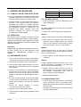
SWITCH
INITIAL SETTING
2.1 STABILITY ADJUST RHEOSTAT (STAB)
Regulator VAR
Fully CCW
● An internal screwdriver adjustable potentiometer
provides adjustment to the response rate of the
generator output voltage to a change in load.
Remote VAR
Centered
2.4 SYSTEM STAR-UP
● Clockwise rotation of this adjustment provides an
increase in the response time and therefore
decreases the amount of voltage overshoot
(increased stability).Counter-clockwise rotation of
this adjustment provides a decrease in the
response time (faster response time) and
therefore increases the amount of voltage
overshoot (decreased stability).
1. Perform preliminary set-up as described in the
above paragraphs.
2.2 OPERATION
RESULT :
The following system operation procedures provide
instructions for adjusting the EA63-4 voltage regulator.
Symptoms resulting from a faulty regulator and certain
generator system problems are included, together with
suggested remedies.
Voltage should build up. If not, perform Field Flashing.
CAUTION !
Meggers and high potential test equipment must not
be used. Incorrect use of such equipment could
damage the semiconductors contained in the
regulator.
2.3 PRELIMINART SET-UP
1. Verify that the voltage regulator specifications
conform with the generator system requirements.
2. Ensure that the regulator wires are as follows:
● If the remote voltage adjust rheostat is not to be
connected, ensure terminals 6 and 7 are shorted
with a jumper.
● If a 55 Hz “corner frequency” for 60 Hz systems is
desired, ensure that the HZ1 and HZ2 terminals
are open. If a 45 Hz “corner frequency” for 50 Hz
systems is terminals are shorted together with a
jumper.
● For 120V nominal sensing, ensure that terminals
V1 and V2 are not connected. For 240V sensing,
ensure that terminals V1 and V2 are connected
together.
3. Ensure the voltage regulator is
connected to the generator system.
correctly
4. Install the fuses as described in Fuses.
NOTE :
All voltage readings are to be taken with an average
reading voltmeter.
2. Start prime mover and bring up to rated speed.
3. Slowly adjust the regulator VAR CW until the
generator output voltage reaches the nominal
value. If used, adjust the remote VAR to set the
generator voltage to the exact value desired.
RESULT:
Voltage should build up to rated value. If voltage
does not build up to rated value, check generator for
short or excessive load.
4. Check regulator normal operating and loading
conditions.
RESULT:
Voltage regulation should be better than ±1.0%
no-load to full-load. If regulation is not within this
range, perform the following steps:
● Voltage reduction under load may be due to
speed change from no load to full load. causing
the frequency compensation (U/F) circuit to
reduce voltage at lower frequencies.
● Replace voltage regulator.
2.5 OPERATIONAL TEST
1. Connect the test setup as shown in the following
figure, Operational Test. Do not apply power.
Ensure that the light bulb is rated for 120V and is
less that 100W.
Complete the following steps before proceeding
with the system start-up.
5. Set the regulator VAR and external VAR (if used)
as follows:
______________________________________________________________________________________
EA63-4
3