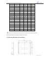
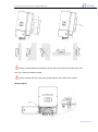
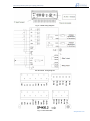
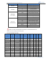
1
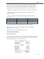
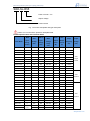
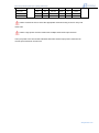
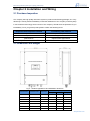
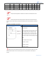
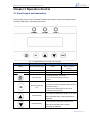
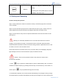
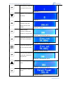
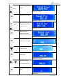
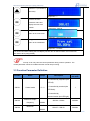
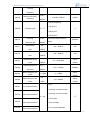
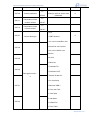
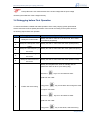
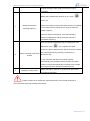
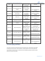
Solar Pumping Inverter User Manual Jaton Technology Limited www.jatontec.com 2015/1/1 Micro-Gird | Off-Grid system | PV Lighting | Solar Pump Introduction Shenzhen Jaton Technology Limited is a New Energy company which focuses on R&D, manufacture and sales of solar power products. We have established a leading position among all domestic Chinese companies in the Off-Grid solar power system and Micro-grid since our establishment in 2006.Jaton fully participate in wind and solar hybrid power system for communication base station construction since 2006 and more 2000 base station systems operate normally at present. We are now providing not only general but also customized products and solutions for our customers. Jaton is a national-level high-tech company with nine subsidiaries, whose business involves on-grid solar power generation system, off-grid solar power generation system, wind-solar hybrid power system, power optimizer,solar pump,solar lamps, etc. It strictly complies with ISO and CE standards and has successively passed the IEC, TUV, JET, MSC, EY105YS, SGS fire tests and gained the CQC Golden Sun Certificate and so on. Certificates www.jatontec.com Micro-Gird | Off-Grid system | PV Lighting | Solar Pump Preface Thank you very much for using the SI65 series of solar pumping inverter produced by Shenzhen Jaton Technology Limited. Please be sure to read this manual carefully before installation and use in order to give full play to the performance of this product and ensure the safety of user and equipment. Please preserve the manual in an orderly manner in order to subsequently facilitate the routine inspection and maintenance of the inverter and find out the cause of abnormity and treatment countermeasure. If there are any puzzling questions or specific requirement during using, please contact the distributors of our company or directly keep in touch with the technology service center of our company. The manual will be subject to change without any further notice. www.jatontec.com Micro-Gird | Off-Grid system | PV Lighting | Solar Pump Contents Safety Instruction ................................................................................................................. 4 Chapter 1 Products Introduction .......................................................................................... 7 1.1 Introduction of Solar Pumping System ................................................................... 7 1.2 Jaton Solar Pumping Inverter Features ................................................................. 7 1.3 Inverter Specification .............................................................................................. 8 Chapter 2 Installation and Wiring ...................................................................................... 11 2.1 Purchase Inspection ............................................................................................. 11 2.2 Dimension and Weight ......................................................................................... 11 2.3 Selecting the place of installation ......................................................................... 12 Chapter 3 Operation Control ............................................................................................. 17 3.1 Panel Layout and Instruction................................................................................ 17 3.2 Setting and Operating .......................................................................................... 18 3.3 Function Parameter Definition .............................................................................. 22 3.4 Debugging before First Operation ........................................................................ 25 Chapter 4 Fault Diagnosis ................................................................................................. 27 4.1 Fault Code Description and Countermeasure...................................................... 27 4.2 Fault Inquiry and Reset ........................................................................................ 28 Chapter 5 Service and Maintenance ................................................................................. 30 5.1 Routine Inspection and Maintenance ................................................................... 30 5.2 Inspection and Replacement of the Damageable Part ........................................ 31 5.3 Storage and Warranty .......................................................................................... 31 Warranty Card .................................................................................................................... 33 Packing List........................................................................................................................ 33 Jaton WARRANTY............................................................................................................. 34 Contact Jaton ..................................................................................................................... 36 www.jatontec.com Micro-Gird | Off-Grid system | PV Lighting | Solar Pump Safety Instruction The equipment is provided with several labels, some of them with a yellow background, which are related to safety issues.Make sure to read the labels and fully understand them before installing the equipment. The symbols are: Equipment grounding conductor (Main grounding protective earth, PE) Alternate Current (AC) value Direct Current (DC) value Phase To avoid risk of electric shock from energy stored in capacitor, please wait for at least 5 minutes to access the 5minutes conductor part of input or output terminals of the inverter after it is disconnected from the output of PV panel and solar pump. Caution: The temperature of metal enclosure may be high during operation. Disposal: Do not dispose of electrical appliances as unsorted municipal waste, use separate collection facilities. Contact your local government for information regarding the collection systems available. If electrical appliances are disposed of in landfills or dumps,hazardous substances can leak into the groundwater and get into the food chain, damaging your health and well-being. www.jatontec.com Micro-Gird | Off-Grid system | PV Lighting | Solar Pump Purchase Inspection Caution 1. Never install if you find inverter damage or lack of component, or else it will cause occurrence of accident. Installation Caution 1. To ensure a good convective cooling effect, the inverter must be installed vertically with at least 10 cm space left in the top and bottom. 2. It’s suitable for indoor and outdoor installations. Install it in the indoor location which is possessed of ventilation opening or ventilating device. It is forbidden to install where exposes directly to the sunlight. 3. Do not let the drilling remains fall into the inverter fin or fan during installation in case that heat dissipation is effected. 4. No user serviceable parts inside. 5. It can apply with all types of PV panel; the systems can operate with or without earthing. Connection Warning 1. Connection job must be performed by qualified electric professionals, or else it will cause electrocution or fire. 2. Please confirm that input power has already been cut off before connection,or else it will cause electrocution or fire. 3. Earth terminal must be reliably grounded, or else the inverter shell will have a danger of being electrified. 4. The type selection of PV array, motor load and inverter must be reasonable,or else the equipment will be damaged. 5. When the photovoltaic array is exposed to light, it supplies a D.C. voltage to the PV inverter. Caution 1. Please use the fasten terminal of the specified torque, or else it will cause fire. www.jatontec.com Micro-Gird | Off-Grid system | PV Lighting | Solar Pump 2. Do not connect the output terminal of the inverter to the capacitor and phase-advanced LC/RC noise filter. It is recommended to use the output reactor when the distance between the inverter and motor load exceeds 100m. Running Warning 1. Energize after confirming the correct connection or else it will damage the inverter or cause fire. 2. Do not modify the connection during electrifying, or else it will cause electrocution. 3. Don’t block any of the ventilation openings. Caution 1. Adjust partial control parameters according to the steps indicated by the manual before its first running. Do not change the control parameters of the inverter randomly, or else it will cause damage to the equipment. 2. Because the heat sink's temperature is high during running, do not touch it for a long time, or else it will cause burn. 3. In the condition of altitude over 1000m, the inverter should be derated for use, that is, output current will be de-rated by 10% at every 1500 m increment of height. Others Warning 1. Maintenance and inspection must be performed by the qualified electric professionals. 2. Do not dismantle the inverter during electrifying. Conduct maintenance and inspection at least 5 minutes after the power off. 3. It is absolutely forbidden to reconstruct the inverter by oneself, or else it will cause personnel injury or equipment damage. 4. Treat the inverter as industrial waste when processing the abandoned inverter. It is possible that the electrolytic capacitor will explode during incineration and that part of components will produce toxic and harmful gas. 5. Pollution degree classification: Pollution degree 3. www.jatontec.com Micro-Gird | Off-Grid system | PV Lighting | Solar Pump Chapter 1 Products Introduction 1.1 Introduction of Solar Pumping System Solar pumping systems produced by Jaton can be applied to daily use (underground water), agricultural irrigation, forestry irrigation, desert control, pasture animal husbandry, water supply for islands, wastewater treatment engineering, and so on. In recent years, with the promotion of the utilization of new energy resources, solar pumping systems are more and more used in municipal engineering, city centre squares, parks, tourist sites, resorts and hotels, the landscapes and fountain systems in the residential areas. The system is composed of a solar array, a pump and a solar pumping inverter (see figure 1-1). Based on the design philosophy that it is better to store water than electricity, there is no energy storing device such as storage battery in the system. Fig. 1-1 Structure of solar pumping system The PV array, an aggregation of many PV modules connected in series and in parallel,absorbs sunlight radiation and converts it into electrical energy, providing dynamical power for the whole system. The pumping inverter controls and adjusts the system operation and converts the DC produced by the PV array into AC to drive the pump, and adjusts the output frequency in real-time according to the variation of sunlight intensity to realize the maximum power point tracking (MPPT). The pump,driven by 3-phase AC motor, can draw water from the deep wells or rivers and lakes to pour into the storage tank or reservoir, or directly connect to the irrigation system,fountain system, etc. According to the actual system demand and installation condition, different types of pumps such as centrifugal pump, axial flow pump, mixed flow pump or deep well pump can be used. 1.2 Jaton Solar Pumping Inverter Features Based on many years of development and experiment, the self-developed pumping inverter (figure 1-1) by our company has the following features:Adopting the proposed dynamic VI www.jatontec.com Micro-Gird | Off-Grid system | PV Lighting | Solar Pump maximum power point tracking (MPPT) control method which has independent intellectual property; Fast response speed and stable operation; Better than the conventional methods which may lead to the problems including poor tracking performances, unstable operation or even damaging water hammer effects when the irradiation on the array changes rapidly. ●Digital control with full automatic running, data storage and complete protective function ●The SI series of solar pumping inverter is produced to drive solarpump, it is more professional and stably. ●The main components of the SI65 series of solar pumping inverter are come from famous suppliers. components suppliers country IGBT module Infineon Capacitance NCC Japan DSP TI America ● Option of up and down water level detection and control circuit is available. ● Protection level IP65 (machine type’s rated power less than 22 kW); ambient temperature for using: -10 ~ +50˚C. ●Protective class: Class I; Overvoltage category PV: OVC II. 1.3 Inverter Specification Label and Type Description Product label is stick to the right side of outer casing, which contains the important information such as product series, voltage, power grade and SW and HW version that’ll provide important basis for product application, maintenance and after service. www.jatontec.com Micro-Gird | Off-Grid system | PV Lighting | Solar Pump SI65-SL-R55 Power of motor(W) Output voltage Product series Fig. 1-2 Product nameplate and type description Caution: Do not tear off the product's nameplate label. Product Specification and Technical Index Recomm. MAX MAX DC Start Input Inverter Model Input Voltage String MAX Output Output Power Current Voltage Voltage (Vdc) Number Rated MPPT Range (Vdc) (W) (A) Output Output Frequency Voltage (Hz) (Vac) (Vdc) SI65-SL-R55 1 80 450 100~400 550 5 0~50/60 SI65-SLA-R55 1 80 450 100~400 550 5 0~50/60 SI65-SL-R75 1 120 450 150~400 750 6.3 0~50/60 SI65-SLA-R75 1 120 450 150~400 750 6.3 0~50/60 SI65-SL-1R1 1 120 450 150~400 1100 8.6 0~50/60 220V Single SI65-SLA-1R1 1 120 450 150~400 1100 8.6 0~50/60 SI65-SL-1R5 1 120 450 200~400 1500 10 0~50/60 SI65-SLA-1R5 1 120 450 200~400 1500 10 0~50/60 SI65-SL-2R2 1 200 450 280~400 2200 14 0~50/60 SI65-SLA-2R2 1 200 450 280~400 2200 14 0~50/60 SI65-TL-R55 1 80 450 120~400 550 4 0~50/60 SI65-TL-R75 1 120 450 150~400 750 5 0~50/60 SI65-TL-1R1 1 120 450 150~400 1100 6 0~50/60 SI65-TL-1R5 1 120 450 200~400 1500 7 0~50/60 SI65-TL-2R2 1 200 450 280~400 2200 11 0~50/60 SI65-TL-2 2 250 900 500~680 3000 8 0~50/60 SI65-TL-4 2 250 900 500~680 4000 10 0~50/60 SI65-TL-5R5 2 250 900 500~680 5500 13 0~50/60 SI65-TL-7R5 3 250 900 500~680 7500 18 0~50/60 SI65-TL-9R2 3 250 900 500~680 9200 21 0~50/60 SI65-TL-11 3 250 900 500~680 11000 24 0~50/60 380V SI65-TL-13 6 250 900 500~680 13000 28 0~50/60 Triphase SI65-TL-15 6 250 900 500~680 15000 30 0~50/60 SI65-TL-18R5 6 250 900 500~680 18500 39 0~50/60 SI65-TL-22 6 250 900 500~680 22000 45 0~50/60 SI54-TL-26 1 (via 250 900 500~680 26000 54 0~50/60 SI54-TL-30 combiner 250 900 500~680 30000 60 0~50/60 Phase 220V Triphase www.jatontec.com Micro-Gird | Off-Grid system | PV Lighting | Solar Pump SI54-TL-37 box) 250 900 500~680 37000 75 0~50/60 SI54-TL-45 250 900 500~680 45000 91 0~50/60 SI54-TL-55 250 900 500~680 55000 112 0~50/60 SI54-TL-75 250 900 500~680 75000 162 0~50/60 Caution: Please be sure to select the appropriate model according to the PV array and motor load. Caution: High-power machine model uses multiple-channel DC input structure. The input power in the above table indicates total multi-channel input power;maximum DC current input should not exceed 15A. www.jatontec.com Micro-Gird | Off-Grid system | PV Lighting | Solar Pump Chapter 2 Installation and Wiring 2.1 Purchase Inspection Our company has high quality assurance system in product manufacturing,package, etc. If any abnormity is found, please immediately contact the distributors of our company or directly keep in touch with the technology service center of our company. We will solve the problems for you immediately. Once you get the product,please confirm the following items: Inspection item Inspection method Consistency with ordered product Inspect the product’s nameplate label Damage or exfoliation phenomenon Inspect whole appearance Completeness of main machine and accessories 2.2 Dimension and Weight Fig. 2-1 Product appearance and installation dimension Pack Size (mm) Inverter Model Protection Level Weight (kg) Length Width Height SI65-SL-R55 IP65 5 405 297 147 SI65-SLA-R55 IP65 5 405 297 147 SI65-SL-R75 IP65 8 405 297 147 SI65-SLA-R75 IP65 8 405 297 147 SI65-SL-1R1 IP65 8 405 297 147 SI65-SLA-1R1 IP65 8 405 297 147 SI65-SL-1R5 IP65 10 405 297 147 www.jatontec.com Micro-Gird | Off-Grid system | PV Lighting | Solar Pump SI65-SLA-1R5 IP65 10 405 297 147 SI65-SL-2R2 IP65 10 405 297 147 SI65-SLA-2R2 IP65 10 405 297 147 SI65-TL-R55 IP65 5 405 297 147 SI65-TL-R75 IP65 8 405 297 147 SI65-TL-1R1 IP65 8 405 297 147 SI65-TL-1R5 IP65 10 405 297 147 SI65-TL-2R2 IP65 10 405 297 147 SI65-TL-2 IP65 14 478 325 155 SI65-TL-4 IP65 14 478 325 155 SI65-TL-5R5 IP65 15 478 325 155 SI65-TL-7R5 IP65 15 563 346 148 SI65-TL-9R2 IP65 15 563 346 148 SI65-TL-11 IP65 15 563 346 148 SI65-TL-13 IP65 16 533 405 190 SI65-TL-15 IP65 16 533 405 190 SI65-TL-18R5 IP65 22 533 405 190 SI65-TL-22 IP65 22 533 405 190 SI54-TL-26 IP54 30 533 405 190 SI54-TL-30 IP54 30 533 405 190 SI54-TL-37 IP54 30 533 405 190 SI54-TL-45 IP54 38 600 465 350 SI54-TL-55 IP54 38 600 465 350 SI54-TL-75 IP54 50 626 508 363 Caution: Most of SI65 series machine types are to be wall mounted. Please ensure that the mounting backplane can support the weight of the inverter. 2.3 Selecting the place of installation www.jatontec.com Micro-Gird | Off-Grid system | PV Lighting | Solar Pump Caution: Please identify with the plug to ensure the exact locations of the DC input “PV+” and “PV-” sockets for different model. Caution: Please ensure the AC output wiring based on the marks of the sockets. Wiring Diagram www.jatontec.com Micro-Gird | Off-Grid system | PV Lighting | Solar Pump Fig. 2-2 SI65 wiring diagram A/O terminals` wiring diagram Fig. 2-3 A/O terminals www.jatontec.com Micro-Gird | Off-Grid system | PV Lighting | Solar Pump Socket Terminal description PV+ To PV array positive PV- To PV array negative PE To Earth U To pump U phrase V To pump V phrase W To pump W phrase +12V Power for water level sensor COM The GND to +12V S1 Auto start S2 Water full(digital signal) S3 Water lack(digital signal) +10V Power for water level sensor GND The GND to +10V AI2 Water full(analogue signal) Water level AI3 Water lack(analogue signal) sensor(analogue) RS485+ 485 communication RS485- 485 communication CANAH CAN communication CANAL CAN communication DC input AC output Water level sensor(digital) Caution: To ensure normal operation of the system, it is recommended to select a suitable wire size according to the following table. Recommended Wire Size Table Recomm-e model nded output current(A) Recommended length output ≤ voltage(V) 30m length≤ 60m length length length length length ≤ ≤ ≤ ≤ ≤ 90m 120m 150m 180m 210m SI65-SL-R5 4 3HP 220V 0.75 1.5 1.5 2.5 2.5 4 4 SI65-SL-R75 5 3HP 220V 0.75 1.5 2.5 2.5 4 4 6 SI65-SL-1R1 6 3HP 220V 1 1.5 2.5 4 4 4 6 SI65-SL-1R5 7 3HP 220V 1 2.5 2.5 4 4 6 6 SI65-SL-2R2 11 3HP 220V 1.5 2.5 2.5 6 6 6 6 SI65-TL-3 8 3HP 380V 1.5 2.5 2.5 6 6 6 6 SI65-TL-4 9 3HP 380V 1.5 2.5 2.5 6 6 6 6 SI65-TL-5R5 13 3HP 380V 2.5 2.5 4 6 6 6 6 SI65-TL-7R5 18 3HP 380V 2.5 4 6 6 10 10 10 SI65-TL-9R2 21 3HP 380V 4 4 6 10 10 10 10 SI65-TL-11 24 3HP 380V 4 6 10 10 10 16 16 SI65-TL-13 28 3HP 380V 6 6 10 10 10 10 10 SI65-TL-15 30 3HP 380V 6 6 10 10 16 16 16 SI65-TL-18R5 39 3HP 380V 6 10 10 16 16 25 25 SI65-TL-22 45 3HP 380V 10 16 16 25 25 www.jatontec.com Micro-Gird | Off-Grid system | PV Lighting | Solar Pump SI54-TL-26 54 3HP 380V 10 16 16 25 25 SI54-TL-30 60 3HP 380V 10 16 25 25 35 SI54-TL-37 75 3HP 380V 16 25 25 35 35 SI54-TL-45 91 3HP 380V 25 35 35 50 112 3HP 380V 35 50 50 SI54-TL-55 Units: mm 2 Prompt: Ambient temperature condition for the above-recommended wire size is ≤50°C. Prompt: High-power wall-mounting machine model uses multi-channel DC input. Wire size of DC of each channel is selected and used as per the recommendation in the above table. Instruction of Float Water Level Switch Description 1.The water level sensor is made up of three bareness wires, 2. When the water level of the cistern is high or the water level of the namma is low, the solar pumping inverter run; When the water level of the cistern is low or the water level of the namma is high, the solar pumping inverter stop. 3.The water sensors must be: ①signal 1 shortest ②signal 2 medium ③signal 3 longest Caution: When use the water level sensors, Please connect high level signal wire to A/O terminals S2 and COM; connect low level signal wire to A/O terminals S3 and COM (see Fig.2-3). www.jatontec.com Micro-Gird | Off-Grid system | PV Lighting | Solar Pump Chapter 3 Operation Control 3.1 Panel Layout and Instruction Solar pumping inverter uses LCD display operating panel which is shown as the figure below, including 3 LED lamps, LCD display and 5 keys. Fig. 3-1 Keyboard layout and name of each part Indicator light and key POWER Running indicator light Function Description Green Bright: Inverter is running ALARM Alarm indicator light Yellow Bright: Inverter is alarm FAULT Fault indicator light Red Bright: System fault 1. Starting control for the inverter; Run /Stop key 2. Stop control for the inverter for long press 2s. 1. Confirm the content to be viewed or edited; Enter/Programming key 2. Confirm and save the parameter value when the parameter is edited; 3. Quit from the display status of the control parameter for long press 2s. 1. Increase the parameter number or its value Increment key when the status of the control parameter is displayed; 1. Decrease the parameter number or its Decrement key value when the status of the control parameter is displayed; www.jatontec.com Micro-Gird | Off-Grid system | PV Lighting | Solar Pump 1. Switch the digit to be edited during data editing. Shift key 2. Viewing the running data when the inverter is display in the main menu. 3.2 Setting and Operating Inverter start-up and operation Step 1: Ensure that the DC cable is connected correctly; unused DC plugs and AC terminal cover is sealed. Step 2: Connect the solar pump to the AC output terminals (see Fig.2-2). If there have a AC switch between the pump and inverter (not suggest), Ensure the AC switch is ON. Step 3: Connect the PV array to the PV input terminals before ensure the DC switch is OFF (see Fig.2-2). Warning: It`s absolutely forbidden to turn on the AC switch when the inverter is working, or may broken the inverter. The smart mind is turn off the DC switch first,wait 5 minutes at least to avoid risk of electric shock from energy stored in capacitor,then turn on the AC switch, and turn on the DC switch at last. Ensure all the wires is corrected connect, turn on the DC switch, the LCDdisplay and power light will bright; then the inverter will drive the pump for wait 60 seconds. Caution: There are two operation modes in the product; the factory set is full-automatic operation: 1: Press key to operate, the initial frequency value is determined by S00.10, and then modifies the output frequency by pressing Increment key or Decrement key. In this mode: it`s need to press key to operate and long press 2s to stop. 2: Full-automatic operation: the inverter will start automatically if the sunlight is strong enough, the output frequency will track automatically according to the sunlight.The control cell array will www.jatontec.com Micro-Gird | Off-Grid system | PV Lighting | Solar Pump export maximum power; in this mode, it isn`t need to control the inverter, it will start automatically if the sunlight is strong enough and stop when the sunlight is weak. It could only view running data and parameter, and use DC switch to control the inverter if you want. Once the solar pump inverter starts, it enters one of the following 3 states in turn: Standby: The PV array can only provide just enough voltage to minimum requirements of the internal controller unit. Try to working: When the PV array DC voltage is greater than 500V, the inverter will try to working. Normal: when the inverter operates and the PV array DC voltage is greater than 500V, the inverter will work normally. The Inverter will keep MPPT function and drive the solar pump when it is in normal operation. Maybe it will stop under the situation of low input DC-power,don’t worry, it will automatically restart again when DC-power from the PV array is sufficient. Warning: The rated power of the pump exceed the inverter, it may broken the inverter; if the rated power of the pump match the inverter, it isn`t need to edit the parameter; if the rated power of the pump not exceed the inverter, it is need to edit the parameter in following steps. E.g. Inverter (7.5kW) drive the pump (5.5kW) Operation Description Display Initial status:non-historical data display Enter the main parameter modification interface for long press 2s Represent:S00 parameter group Press OK key to enter the branch menu Represent:S00.00 Press UP key to view the S00.01 Represent:S00.01 www.jatontec.com Micro-Gird | Off-Grid system | PV Lighting | Solar Pump Press OK key to enter the S00.01(the factory set is 1) Represent:1 Edited it to 0(controlled by keyboard) Represent:0 Press to save the parameter value and display the next code number Represent:S00.03 Return the main parameter modification interface for long press 2s Represent:S00 parameter group Long press OK for 2s to return to the initial status Represent:Working freq. 50.00Hz Long press ON/OFF key for 2s to stop the inverter. Represent:Set freq. 50.00Hz Enter the main parameter modification interface for long press 2s Represent:S00 parameter group Press the UP key to S02 group Represent:S02 parameter group Press OK key to enter the S02.01 Represent:S02.01 www.jatontec.com Micro-Gird | Off-Grid system | PV Lighting | Solar Pump Edited the rated power to and 5.5kW Represent:5.5kW Press OK turn to S02.02 Represent:S02.02 Edited the rated current of and the pump(it will write in pump)e.g.11.3A Represent:11.3A Press to save the parameter value and return to the branch menu Represent:S00 parameter group Long press OK for 2s to return to the main menu Represent:S02 parameter group Press DOWN key to S00 parameter group. Represent:S00 parameter group Press OK key to enter the branch menu. Represent:S00.00 Press UP or DOWN or key to view the S00.01 Represent:S00.01 Press OK key to enter the S00.01. Represent:0 www.jatontec.com Micro-Gird | Off-Grid system | PV Lighting | Solar Pump Edited it to 1(controlled by terminals) Represent:1 Press to save the parameter value and display the next code number. Represent:S00.03 Long press OK for 2s to return to the main menu. Represent:S00 parameter group Long press OK for 2s to return to the initialstatus. Represent:50.00Hz Turn off the DC switch,waiting the LCD display off, then turn on the DC switch, the inverter will auto-start to drive pump(5.5kW) Prompt: It can only view the control parameter during inverter operation. The control parameter cannot be modified until the inverter stops running. 3.3 Function Parameter Definition Number Name Scope Description Factory set value 0: Controlled by keyboard (the LED off). S00.01 Control mode 0~2 1: Controlled by terminal (the 1 LED flash). 2: Controlled by communication (the LED light). S00.03 Maximum output frequency S00.04 Maximum 10Hz ~ S00.04 ~ 600Hz 50.00Hz S00.05 ~ S00.03 50.00Hz 600Hz S00.06 ~ S00.03 www.jatontec.com Micro-Gird | Off-Grid system | PV Lighting | Solar Pump running frequency S00.05 Minimum Running frequency 0.00 ~ 0.00 Hz~ S00.04 0.00Hz S00.04 0. Set by keyboard 1. Set by AI1 S00.06 Frequency set 0 ~ 11 0 2. Set by AI2 3. Set by AI3 Running 0.00 ~ S00.10 frequency set S00.04 Acceleration 0.0 ~ Only set in manual control model S00.11 time 3600.0 Deceleration 0.0 ~ S00.12 time S02.01 Rated power of the S02.05 0.0 ~ 3600.0s 22s 0.0 ~ 3600.0s 10s 3600.0 0.1 ~ 0.1 ~ 3000.0kW motor 3000.0 Rated frequency of 0.01 ~ 0.01 ~ S00.03 the motor S00.03 Rated voltage of the motor 0 ~ 1200 Rated current of the motor Set by model S02.02 S02.04 50.00Hz 0 ~ 1200V 50.00Hz Set by model 0.8 ~ 0.8 ~ 6000A Set by model 6000 0. null S05.01 S1 terminal function 1. Running in forward model S05.02 2. Running in reverse model S2 terminal function 0 0 ~ 63 7. Fault reset S05.03 S3 terminal function S05.04 S4 terminal function 8. Run and stop 42. PV inverter forbidden www.jatontec.com Micro-Gird | Off-Grid system | PV Lighting | Solar Pump 43. Water full 0~ S07.00 Custom password You must enter the password whenyou want to view or edit 65535 S07.11 Temperature of the rectifier module S07.12 Temperature of the inverter module 0 parameter 0~ 100.0℃ 0~ 100.0℃ 0. null S07.27 Current fault type 1. IGBT Shortcut 0 2. Inc over Current/Dec over Current/Con over Current S07.28 3. Inc over Volt/Dec over Volt/Con over Volt S07.29 4. Vbus low 5. Overload Tel S07.30 6. Overload VVVF Fault type record 1 ~ 5 7. Scarce Phase Out 8. Inv Overtemp S07.31 9. Shortcut GND 1 10. Curr test Fault 11. Lack load 12. No Water S07.32 13. Water Full 14. Com Fault www.jatontec.com Micro-Gird | Off-Grid system | PV Lighting | Solar Pump Prompt: Record is not made because of the under-voltage fault of input voltage caused by the weakness of the sunlight intensity. 3.4 Debugging before First Operation To ensure the efficient, reliable and stable operation of the solar pumping system,professional electric technician must set partial parameters of the inverter according to the system structure as following steps before first operation. Steps Debugging contents 1 Modify the control mode 2 3 4 5 Modify the rated power of the Operating method Modify the S00.01 value as 0. (in this mode, the inverter controlled by keyboard) Modify the S02.01 value follow the motor (Rated power). motor Modify the rated frequency of Modify the S02.02 value follow the motor (Rated frequency). the motor Modify the rated voltage of Modify the S02.04 value follow the motor (Rated voltage). the motor Modify the rated current of Modify the S02.05 value follow the motor (Rated current). the motor Modify S15.00 parameter value as 0.Modify S00.10 parameter value as 30.00. (in a shining day) Press the key to run and observe water yield from the outlet. 6 Confirm the motor wiring Long press key to shut down and change the order of output connection. Press the key to run and observe water yield from the outlet. Long press key to shut down; select the wiring www.jatontec.com Micro-Gird | Off-Grid system | PV Lighting | Solar Pump method with larger water yield to ensure the pump’s corotation. Modify S00.10 parameter value as 10.00. Press key to run. 7 Modify the minimum Observe the effluent of the water outlet.If there is no effluent operating frequency in the outlet, press Increment key to slowly increase the output frequency. If there is effluent of the pump, record the operating frequency f.Modify the S00.05 parameter value as f (shutdown frequency). User sets S15.00 (operating mode) according to his own demand.0: Press key to operate, the initial frequency value is determined by S00.10, and then modifies the output frequency by pressing Increment key or 8 Set the operating mode of the Decrement key. inverter 1: Full-automatic operation: the inverter will start automatically if the sunlight is strong enough, the output frequency will track automatically according to the sunlight. The control cell array will export maximum power. 9 Modify the control mode Modify the S00.01 value as 1. (in this mode, the inverter controlled by terminals) Caution: Please do not modify the control parameters of the inverter randomly,or else it will cause abnormal working of the system. www.jatontec.com Micro-Gird | Off-Grid system | PV Lighting | Solar Pump Chapter 4 Fault Diagnosis 4.1 Fault Code Description and Countermeasure SI65 series solar pumping inverter has perfect protection. When the system fault occurs, the inverter will take protection measures: general protection measure is to stop driving signals output of the motor (breakaway) immediately while the restart is forbidden for a certain period of time. It will automatically switch to the fault display unit when fault or protection occurs. The fault code will be displayed in the middle of the LCD and flash. You can cut off the input power supply and get electricity until the internal power supply is cut.If the fault still exists after reset, please contact the manufacturer and make relevant processing. After the fault or protection to be reset is eliminated, the inverter will conduct automatically a time-delayed restart. At this time the fault number will appear in the left side of the LCD. The right will display the countdown of the restart, when the countdown is 0, fault display unit will disappear automatically and operating status data will be displayed. Code Code description Possible reason Countermeasures PV array voltage is lower When PV voltage is upto Power off to the start value the start value, pumping system will automatic start. Too weak sunlight intensity Inc over Volt Dec over Volt Over-voltage Too high input Inspect PV array voltage voltage Con over Volt Too low input Voltage Vbus low Under-voltage Too weak sunlight Inspect PV array voltage. intensity Inc over Too large pump Current Dec over Current Over-current arrayvoltage Too Con over long motor wiring Current Overload Tel Overload loadLow PV Too much power for the pump Over load for the inverter Change low-power pump load Inspect PV array voltage Reduce the connection between inverter and motor. The rated power of Reduce the highest the pump not match operating frequency of the the inverter inverter. The rated power of Change a smaller power of www.jatontec.com Micro-Gird | Off-Grid system | PV Lighting | Solar Pump VVVF the pump not match the pump the inverter IGBT shortcut Inv Overtemp Scarce Phase Over-current of the IGBT module Over-temperature of the IGBT module Output error Out Shortcut GND 1 Curr test Fault Lack load No Water Shorted to the Ground CT fault pump running empty Too low of the water level Shorted output or grounding Module damaged service Clear the air duct or high ambient improve the ventilation temperature condition Error connection Inspect the connection IGBT module Turn to manufacturer for damaged service Error connection Inspect the connection Device or circuit Turn to manufacturer for damaged service Pumping To check with water empty,pump wire are level,pump wire all broken, pump is connection, pump rate is not match with match with inverter inverter. capacity or not. Pumping empty A/O To check with water level terminals connection Cistern full A/O Too high of the water level Turn to manufacturer for Air duct blocked Too error Water Full Inspect the connection terminals connection error A/O terminals connection To check with water level A/O terminals connection Restart Device or circuit Com Fault Communication fault damaged Turn to manufacturer for service 4.2 Fault Inquiry and Reset This series of inverters record the fault codes of the latest 5 times. Searching this information will help find the fault cause. Fault information is stored together with the control parameter, code numbers are S07.28~S07.32. Please refer to the keyboard operation method to search and find out relevant information. www.jatontec.com Micro-Gird | Off-Grid system | PV Lighting | Solar Pump Caution: Completely check up on the fault cause and eliminate it before reset.If it cannot be reset or goes wrong after reset, check up on the cause, because continuous reset will damage the inverter. Caution: Delay 5 minutes to reset during overload and overheat protection. www.jatontec.com Micro-Gird | Off-Grid system | PV Lighting | Solar Pump Chapter 5 Service and Maintenance 5.1 Routine Inspection and Maintenance Affected by ambient temperature, humidity, dust, vibration and internal device aging of the inverter, the inverter will appear some potential problems during operation. To make the inverter run stably for longer time, a periodic inspect must be exerted every year. Requirement of Inspection and Maintenance The inspection must be performed by professional technical personnel, if necessary, cut off power supply of the inverter first. Avoid leaving the metal components in the inverter, or else it will cause damage to the equipment. Electric insulation test has been made on the inverter before it is leaving factory,so the user doesn’t have to carry on a withstand-voltage test. If it is necessary to conduct insulation test on the inverter, all the input and output terminals must be reliably shorted. It is forbidden to conduct insulation test on single terminal. Use the 500V megohmmeter to conduct the test. It is forbidden to use the megohmmeter to test in the control circuit. When conducting insulation test on the motor, you have to dismantle the connection between motor and inverter. Main Points for Inspection and Maintenance Please use the inverter under environment recommended by this manual. Inspect and maintain as per the following table. Inspect frequency Routine Regular Inspection Inspection content Judgment standard item 1. Temperature<50°C. Running √ environment 1.temperature,humidity 2. dust, gas 2. Humidity <90%, no dew condensation.No peculiar smell,flammable,explosive gas. √ Cooling 1. Installation 1. Excellent ventilation in www.jatontec.com Micro-Gird | Off-Grid system | PV Lighting | Solar Pump system environment installation environment. 2. Radiator 2. Radiator air duct not blocked. 1. Stable vibration,normal 1.Vibration,temperature temperature of the shell. rise. √ 2. No abnormal noise and Inverter body 2. Noise peculiar smell. 3. Lead, terminal 3. Fastening screw not loosen. 1.Vibration,temperature √ Motor rise. 2. Noise 1. Steady running and normal temperature. 2. No abnormal and uneven noise. 1. Input voltage in the Input and √ 1. Input voltage specified scope. 2. Output current 2. Output current under the output parameter rated value. 5.2 Inspection and Replacement of the Damageable Part Filter Capacitor Pulsating current of the main circuit will influence the performance of the aluminum electrolytic filter capacitor, of which the degree will depend on the ambient temperature and application condition. The inverter used under normal condition should replace its electrolytic capacitor every 10 years. When the filter capacitor’s electrolyte is leaking, safety valve bursting out or the capacitor main body expanding,replace it immediately. Cooling Fan Of SI65 series of pumping inverter, all the inverters above SI65 22kW have cooling fans inside. Cooling fan’s service life is about 1, 5000 hours. If the fan appears abnormal noise or produces vibration, replace it immediately. 5.3 Storage and Warranty Storage www.jatontec.com Micro-Gird | Off-Grid system | PV Lighting | Solar Pump If the storage is not used temporarily or stored for long time after purchasing, the following notice should be paid attention to. Avoid placing the inverter in high temperature or humid place or where there is vibration and metal dust, and excellent ventilation should be ensured. Inside filter capacitor performance of the inverter will decline for long–time disuse. It is necessary to energize one time every 2 years to restore the performance of the filter capacitor and inspect the inverter function at the same time. It is necessary to increase the voltage through a DC power supply during energizing with power-on time not less than 5 hours. Warranty The warranty of this inverter is 2 years. When any fault or damage occurs on the product, within the warranty period, our company will provide free maintenance.After the warranty time, we can provide lifetime paid warranty service. Certain maintenance charge should be considered during warranty period if the fault is caused by the following reason: 1. Fault caused by operating against the manual or surpass the standard specification 2. Fault caused by self fix and modification without permission. 3. Fault caused by poor preservation 4. Fault by using the inverter in abnormal function 5. Machine damage caused by fire, salt corrosion, gas corrosion, earthquake,storm, flood, lightning, abnormal voltage or other force majeure. Prompt: Warranty only covers the body of the inverter. www.jatontec.com Micro-Gird | Off-Grid system | PV Lighting | Solar Pump Warranty Card Client name Contact person Client address Telephone number Product type Date of purchase Warranty length Machine frame code (From the leaving factory day.) Distributor (Seal) Packing List 1. Main machine, 1 2. Operation manual( including warranty card), 1 3. Plug of the positive electrode of the PV array, 1 4. Plug of the negative electrode of the PV array, 1 5. Water level sensor plug, 1 (matching) www.jatontec.com Micro-Gird | Off-Grid system | PV Lighting | Solar Pump Jaton WARRANTY Warranty Policy: Warranty Period: The Jaton SI65 Series Solar pumping inverters provided by Shenzhen Jaton Tech. Co., LTD. (abbr. Jaton) have 24-month warranty period. The system accessories provided by Jaton have 12-month warranty period. Warranty Time Start: From the date that you get goods from our distributors. Warranty Evidence: The Purchasing Invoice from the distributors & Product Series No. Note: Jaton will count from 2 months later according to ex-factory date as the warranty start time if client fails to provide the purchasing invoice and other documents. Scope: Any damages that occur during the WARRANTY PERIOD will be evaluated by Distributor and Jaton to define its scope and responsibility. Warranty Principles: To provide better service to Jaton’s end users, all Jaton’s authorized distributors are requested to respond to end users’ warranty claim, and the authorized distributors will replace any products or parts of the product during the warranty period proved to be defective in design or manufacture. The following cases will be excluded from the warranty (the Distributors are liablefor investigation of the following): 1) “Warranty Card” not being sent back to distributor or Jaton. 2) Product modified or design changed or parts replaced not approved by Jaton 3) Modifications, changes, or attempted repairs and erase series number or seals by non Jaton’s technician. 4) Incorrect installation or commissioning 5) Failure to observe the applicable safety regulations (G59-2.) 6) The Product has been improperly stored and damaged while being stored by the end user. 7) Transport damage, Painting scratch caused by shipping pumping. It should declare to insurance company as soon as containers unload with enough evidence. 8) Failure to observe the user manual, the installation guide, and the maintenance regulations www.jatontec.com Micro-Gird | Off-Grid system | PV Lighting | Solar Pump 9) Incorrect use or inappropriate operation 10) Insufficient ventilation of the device 11) The maintenance procedures relating to such product have not been observed or performed to an acceptable standard. 12) Force majeure (e.g., lightning, overvoltage, storm, fire) Claims that go beyond the rights cited in the warranty principles, in particular claims for compensation for direct or indirect damages arising from the defective device, for compensation for costs arising from disassembly and installation, or loss of profits are not covered by Jaton’s warranty, insofar Jaton is not subject to statutory liability. Warranty Claim Procedure: Please report defective devices with a brief error description to the Jaton’s distributors. If we agree to a replacement, we generally send an equivalent replacement device according to model and age, the remainder of the warranty entitlement will be transferred to the replacement device. In this case, you do not receive a new certificate since your entitlement is documented at Jaton. The replacement will be packaged appropriately for transport and shipped out within 2 working days. The defective device is to be packed in this transport packaging for return transport to the distributor. If the on-site service of re-installation is necessary, the end customers need to negotiate with the distributors in advance. All warranty services in warranty period are free of charge. www.jatontec.com Micro-Gird | Off-Grid system | PV Lighting | Solar Pump Contact Jaton Jaton Technology Limited Add:zhuguang industrial Park,Xili town,Nanshan district,Shenzhen City China Web:www.jatontec.com Sales Email:[email protected] Service Email:[email protected] www.jatontec.com


![[1]StorageTek Linear Tape File System, Open Edition](http://vs1.manualzilla.com/store/data/005641506_1-83def2383162ce3771fdbc891794971f-150x150.png)