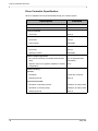
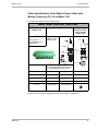
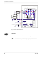
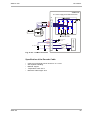
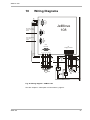
1
JetMove 108 Digital Servo Amplifier 60875640 Introduction Item # 60875640 Revision 2.12.2 October 2012 / Printed in Germany Jetter AG reserve the right to make alterations to its products in the interest of technical progress. These alterations will not necessarily be documented in every single case. This manual and the information contained herein have been compiled with due diligence. However, Jetter AG assume no liability for printing or other errors or damages arising from such errors. The brand names and product names mentioned in this manual are trade marks or registered trade marks of the respective title owner. 2 Jetter AG JetMove 108 Introduction How to Contact us: Jetter AG Graeterstrasse 2 D-71642 Ludwigsburg Germany Phone - Switchboard: Phone - Sales: Phone - Technical Hotline: ++49 7141/2550-0 ++49 7141/2550-433 ++49 7141/2550-444 Telefax - Sales: E-Mail - Sales: E-Mail - Technical Hotline: Internet Address: ++49 7141/2550-484 [email protected] [email protected] http://www.jetter.de This User Manual is an Integral Part of the JetMove 108: Type: Serial #: Year of manufacture: Order #: To be entered by the customer: Inventory #: Place of operation: Jetter AG 3 Introduction Significance of this User Manual This operator's manual is an integral part of the digital servo amplifier JetMove 108 and • • must be kept in a way that it is always at hand until the the digital servo amplifier JetMove 108 will be disposed of. Pass this manual on if the digital servo amplifier JetMove 108 is sold or loaned/ leased out. In any case you encounter difficulties to clearly understand this user manual, please contact the manufacturer. We would appreciate any suggestions and contributions on your part and would ask you to contact us. This will help us to produce manuals that are more user-friendly and to address your wishes and requirements. This manual contains important information on how to transport, erect, install, operate, maintain and repair the digital servo amplifier JetMove 108. Therefore, the persons carrying out these jobs must carefully read, understand and observe this manual, and especially the safety instructions. Missing or inadequate knowledge of the manual results in the loss of any claim of liability on part of Jetter AG. Therefore, the operating company is recommended to have the instruction of the persons concerned confirmed in writing. System Requirements This user manual is giving a description of the servo amplifier JetMove 108 with operating system version 2.12.0.0. History 4 Revision Remarks 2.12.2 Original version in English Jetter AG JetMove 108 Introduction Description of Symbols This sign is to indicate a possible impending danger of serious physical damage or death. Warning This sign is to indicate a possible impending danger of light physical damage. This sign is also to warn you of material damage. Caution This sign indicates hazard of life due to electric shock caused by a high operating voltage. This sign is to indicate hazard of serious physical damage or death due to accidentally touching dangerous parts of the device. This sign is to indicate a possible impending situation which might bring damage to the product or to its surroundings. It also identifies requirements necessary to ensure faultless operation. Important You will be informed of various possible applications and will receive further useful suggestions. It also gives you words of advice on how to efficiently use hardware and software in order to avoid unnecessary efforts. Note ·/- Enumerations are marked by full stops, strokes or scores. Operating instructions are marked by this arrow. Automatically running processes or results to be achieved are marked by this arrow. Jetter AG 5 Introduction Reference to PC keyboard and HMI keys. This symbol informs you of additional references (data sheets, literature, etc.) associated with the given subject, product, etc. Further, this text provides helpful hints for your guidance through the manual. 6 Jetter AG JetMove 108 Table of Contents Contents 1 Safety Instructions 11 1.1 General Safety Instructions 11 1.1.1 1.1.2 1.1.3 1.1.4 1.1.5 1.1.6 Intended Conditions of Use Usage Other Than Intended Personnel Qualification Modifications and Alterations to the Module Repair and Maintenance Disposal 11 11 12 12 13 13 1.2 Ensure Your Own Safety 14 1.2.1 1.2.2 1.2.3 Malfunctions Information Signs and Labels Earthing procedure 14 14 15 1.3 Residual Dangers 15 1.3.1 Hazards during Operation 15 1.4 Instructions on EMC 16 2 Installing the JetMove 108 19 2.1 Scope of delivery 19 2.2 Mechanical Installation 20 2.3 Electrical Installation 23 2.4 Checking the Installation 24 2.5 Notes on Safety as regards Commissioning 25 3 Operating Conditions 27 4 Physical Dimensions 33 5 Technical Specifications 35 5.1 Electrical Specification 35 5.2 Motor Protection 38 5.2.1 I²t Calculation 38 6 Drive Controller Structure 41 7 Description of Connections 43 7.1 Demands on the Power Supply Unit for Motor Operating Voltage 43 7.1.1 Recommendations on the power supply circuit breaker +Vmot 44 7.1.2 General remarks 45 7.1.3 Recommendations on preventing overvoltage at braking or lowering a vertical load 46 7.2 Jetter AG Power Supply 50 7 Table of Contents JetWeb 7.3 Servo Motor 7.3.1 Motor with male connector 7.3.2 Motor with screw clamping terminals and cables with male connectors 7.3.3 Motor with screw clamping terminals and cables with male connectors 7.3.4 Pre-fabricated motor cable with SC mating connector 7.3.5 Motor Cable Permanently Fixed to the Motor 52 54 54 55 56 59 7.4 Brush-Type DC Motor 61 7.5 2-Phase Stepper Motor 63 7.5.1 7.5.2 Stepper motor control Acceleration and deceleration 65 67 7.6 LinMot 7.7 Connection of the Resolver 71 7.7.1 7.7.2 7.7.3 Specification Resolver Cable With Mating Connector Resolver Cable Without Mating Connector 71 71 73 7.8 Sin- / Cos-Encoder Connection 74 7.8.1 Specification 74 7.9 Connection of the Incremental Encoder 77 7.9.1 Specification 77 7.10 Digital and Analog Inputs and Outputs 80 7.11 Jetter System Bus 82 7.11.1 JETTER System Bus Cable Specification 82 8 Status Monitoring 85 9 Diagnostics 87 9.1 Error Messages 87 9.2 Alarms 90 10 Wiring Diagrams 91 11 Ordering Information 93 11.1 List of Documentation 93 11.2 Device 93 11.3 Motor power cable with mating connector SC 94 11.4 Resolver Cable 95 11.5 System Bus Cable 95 List of Appendices 8 Jetter AG JetMove 108 Table of Contents Appendix A: Appendix B: Appendix C: Appendix D: Jetter AG Recent revisions Glossary List of Illustrations Index 99 100 103 104 9 Table of Contents JetWeb 10 Jetter AG JetMove 108 Contents 1.1 General Safety Instructions 1 Safety Instructions 1.1 General Safety Instructions The digital servo amplifier JetMove 108 meets the applicable safety regulations and standards. Special emphasis was given to the safety of the users. Further, the user should adhere to the following regulations: • pertinent accident prevention regulations; • accepted safety rules; • EC guidelines and other country-specific regulations. 1.1.1 Intended Conditions of Use Usage according to the intended conditions of use includes operation in accordance with these operating instructions. The digital servo amplifier JetMove 108 may only be operated in the closed control cabinet and within the range of the set values, see chapter 5 "Technical Specifications", page 35. Do not apply a voltage to the digital servo amplifier JetMove 108 that is higher than the specified operating voltage. The operating voltage for motor supply by the digital servo amplifier JetMove 108 ranges between 12 V and 48 V DC. Thus, the digital servo amplifier is not subject to the EG Low Voltage Directive. The servo amplifier JetMove 108 is for driving electric motors of various designs. The winding insulation of the motors must be higher than, or at least equal to, the DC link voltage supplied by the servo amplifier. The digital servo amplifier JetMove 108 is used to drive machinery, such as conveyors, production machines, and handling machines. 1.1.2 Usage Other Than Intended This digital servo amplifier must not be used in technical systems which to a high degree have to be fail-safe, e.g. ropeways and aeroplanes. Do not use the integrated braking circuit in applications, where, in case of braking circuit failure, safety hazards can occur. The servo amplifier JetMove 108 is not a safety-relevant device according to the machinery directive 2006/42/EG. Therefore, using this servo amplifier for safety-relevant applications as regards safety of persons is neither adequate nor permitted. Jetter AG 11 1 Safety Instructions If the digital servo amplifier JetMove 108 is to be run under operating conditions, which differ from the conditions mentioned in chapter 3 "Operating Conditions", page 27, the manufacturer must be contacted beforehand. 1.1.3 Personnel Qualification Depending on the life cycle of the product, the persons involved must possess different qualifications. These demands have to be met, in order to grant safety in handling the JetMove 108 at each phase of the product life cycle. Product Life Cycle Minimum Qualification Transport / Storage: Trained and instructed personnel with knowledge in handling electrostatic sensitive components. Mounting / Installation: Specialized personnel with training in electrical engineering, such as industrial electronics engineer. Commissioning / Programming: Trained and instructed experts with profound knowledge of, and experience with, electrical / drive engineering, such as electronics engineer for automation technology. Operation: Trained, instructed and assigned personnel with knowledge in operating electronic devices. Decommissioning: Specialized personnel with training in electrical engineering, such as industrial electronics technician. 1.1.4 Modifications and Alterations to the Module Due to safety reasons, neither opening the digital servo amplifier JetMove 108, nor carrying out any modifications or alterations to the device and its functions is allowed. Any modifications to the servo amplifier JetMove 108 not expressly authorized by the manufacturer will result in a loss of any liability claims to Jetter AG. The original parts are specifically designed for the servo amplifier JetMove 108. Parts and equipment from other manufacturers are not tested on our part, and are, therefore, not released by Jetter AG. The installation of such parts may impair the safety and the proper functioning of the digital servo amplifier JetMove 108. Any liability on the part of Jetter AG for any damages resulting from the use of nonoriginal parts and equipment is excluded. 12 Jetter AG JetMove 108 1.1 General Safety Instructions 1.1.5 Repair and Maintenance Repairs to the digital servo amplifier JetMove 108 must not be carried out by the operator. The servo amplifier JetMove 108 does not contain any parts to be repaired by the operator. For being repaired, the servo amplifier JetMove 108 must be sent to Jetter AG. The digital servo amplifier JetMove 108 is maintenance-free. Therefore, absolutely no inspection or maintenance works are required for the operation of this device. 1.1.6 Disposal In case of obvious damage or erratic behaviour, the servo amplifier must not be used any more. When disposing of devices, the local environmental regulations must be complied with. You can disassemble the digital servo amplifier JetMove 108 into its main components by unscrewing it (aluminum heat sink and side plate, steel casing cover, PCBs). Jetter AG 13 1 Safety Instructions 1.2 Ensure Your Own Safety Isolate the digital servo amplifier JetMove 108 from the mains, if maintenance works have to be carried out. By doing so, you will prevent accidents resulting from electric voltage and moving parts. Follow the information given in chapter 1.3 "Residual Dangers", page 15. Warning Safety and protective devices, e.g. guards, must not in any case be shunted or by-passed. Prior to commissioning reattach dismantled protective equipment, such as guards, and check them for proper functioning. Prior to commissioning, the machine manufacturer shall conduct a hazard analysis for the machine and take appropriate measures to prevent personal injury and damage to property resulting from accidental movements. 1.2.1 Malfunctions In the case of malfunctions or other faults, immediately separate the digital servo amplifier JetMove 108 from the mains. Follow the information given in chapter 1.3 "Residual Dangers", page 15. Immediately report any malfunctions or other damages to the responsible person. Secure the servo amplifier JetMove 108 against misuse or accidental use. 1.2.2 Information Signs and Labels Follow the instructions given on markings, information signs, and labels. Keep markings, signs and labels readable. Replace damaged or unreadable information signs and labels. 14 Jetter AG JetMove 108 1.3 Residual Dangers 1.2.3 Earthing procedure Screw the enclosure of the digital servo amplifier JetMove 108 down to a highly conducting, plane and earthed panel. Connect the earthing terminal (X1:PE) to an earth point. Use a short line of a great cross-section. 1.3 Residual Dangers 1.3.1 Hazards during Operation WARNING! Hot Surfaces! During operation, the surfaces, respectively the heat sinks of the servo amplifier JetMove 108 can heat up. The left sidewall and the rear panel can reach temperatures of up to 85 °C. Warning Do not touch the left sidewall or rear panel of the servo amplifier JetMove 108 during operation and after switching off, while the device is still cooling down. Make sure that no temperature-sensitive parts have been connected or fastened to the servo amplifier JetMove 108. DANGER in a potentially explosive atmosphere! Do not operate the digital servo amplifier JetMove 108 in a potentially explosive atmosphere. Warning Jetter AG 15 1 Safety Instructions DANGER of injuries caused by mechanic force! Caution The digital servo amplifier JetMove 108 drives a motor. This motor moves mechanic parts or sharp edges. Therefore, failure or malfunctioning of the digital servo amplifier JetMove 108 can be dangerous for persons or damage the machinery. This should be prevented by installing additional safety devices. • One safety precaution is to install a second set of limit switches to interrupt the power supply of the motor. • Another safety precaution would be installing a guard. Make sure that hazards to persons are precluded even when the drive is rotating unintentionally. Do not remove any guards. Do not wear gloves, lest they could get caught in the rotating drive shaft. Never touch a rotating drive shaft. Warning Do not touch the motor during or after operation: Temperatures can reach as high as 140 °C. 1.4 Instructions on EMC The digital servo amplifier JetMove 108 is intended for use in industrial environment. It may cause radio interferences when used in residential areas. It is operated at the operator's own risk. The electromagnetic immunity of a system depends on the weakest component of the system. For this reason, correct wiring and shielding of cables is of paramount importance. Important! Measures for increasing EMC in electric plants: Earth the device adequately according to chapter 1.2.3 "Earthing procedure", page 15. 16 Jetter AG JetMove 108 1.4 Instructions on EMC Connect the motor cable. If applicable, an optional PE bus must be near the servo amplifier. Shield cables on both ends. If a motor power cable is used which includes cores for brake control, the brake control cores must be separately shielded. The shielding braid must be connected on both ends of the cables. Follow the instructions given in Application Note 016 "EMC-Compatible Installation of the Electric Cabinet" published by Jetter AG. The following instructions are excerpts from Application Note 016: Screw the enclosure of the digital servo amplifier JetMove 108 down to a highly conducting, plane and earthed panel. Keep signal and power lines physically separated. We recommend spacings greater than 20 cm. Cables and lines should cross each other at an angle of 90°. Shielded cables must be used for the following lines: Analog lines, data lines, motor cables coming from inverter drives (servo output stage, frequency converter), lines between components and interference suppressor filter, if the suppressor filter has not been placed at the component directly. Both ends of the cable must be shielded. Unshielded wire ends of shielded cables should be as short as possible. The entire shield must be drawn behind the isolation, and then be clamped under an earthed strain relief with the greatest possible surface area. When male connectors are used: The shield (impedance shielding) must, in its entire perimeter, be drawn behind the shielding clamp of the metallized connector housing, respectively of the EMC gland bushing, its greatest possible surface area being clamped under the strain relief of the JetMove 108. Only use metallized connectors, e.g. SUB-D with metallized housing. Make sure that the strain relief is directly connected with the housing here as well (see Fig. 1). Jetter AG 17 1 Safety Instructions Fig. 1: Shielding of SUB-D connectors in conformity with EMC standards If the shield cannot be attached to the connector, for example, with a screw type terminal: It is important that shield and strain relief are highly conductive and directly connected to a grounded surface with the greatest possible surface area. When doing so, grounding must be implemented in a way that the unshielded portion of the cable is as short as possible (refer to Fig. 2). JetMove 108 Metal Rail Shield Motor Cable Fig. 2: Shielding of screw terminals to EMC standards 18 Jetter AG JetMove 108 2.1 Scope of delivery 2 Installing the JetMove 108 2.1 Scope of delivery • • • Digital servo amplifier JetMove 108 Mating connector plugged-on User Manual Accessories The accessories are not part of the scope of delivery! • System bus cable of cable confection no. 530 x.x m; length: 0.2 m through 5.0 m See also chapter 7.11 "Jetter System Bus", page 82. • Motor power cable, see also chapter 7.3 "Servo Motor", page 52. • Encoder cable, see also chapter 7.7 "Connection of the Resolver", page 71. • Motors, e.g. synchronous servo motors of the Jetter motor series JL1 or JH2. • DC power supply unit • Ballast Resistor Note! If you are not sure which mounting accessories you will need, please contact Jetter AG. Jetter AG 19 2 Installing the JetMove 108 2.2 Mechanical Installation Prior to installing the digital servo amplifier check it for possible transport damages. Please check the shipment for completeness. To ensure proper functioning of the JetMove 108, check whether the mounting plate in the electric cabinet is unpainted. The JetMove 108 has been designed for natural convection. Mount the JetMove in horizontal orientation (label on top) or vertical orientation (motor line below). In both cases, make sure there is a clearance of 25 mm between the JetMove and adjacent devices (see Fig. 4, Page 22). Make sure there is a clearance of at least 25 mm under and above the JetMove 108 - unobstructed ventilation must be granted. Mark on the panel two positions for the fastening screw threads of the JetMove 108 (see Fig. 4, Page 22). Drill the holes and cut the respective threads (M4) into the panel. Screw the lower fitting screws into the thread by approximately half of their length. By means of the oblong holes in the rear plate, hang up the JetMove 108 by the fitting screws; then screw them down tightly. Screw down the upper fitting screws. 20 Jetter AG JetMove 108 2.2 Mechanical Installation m m 5 2 . n i m Fig. 3: Recommended mounting Jetter AG 21 15 26 (2 x) 4 4, 2 2 Installing the JetMove 108 JM-108 Output Ratings: Power Supply: Rev.: Part No.: 10000749 1 * 24-48VDC Current: 16A Voltage: 3 * 17-34VAC, 0-400Hz Motor Current: Enclosure Rating: IP20 Made in Germany 0 - 40°C, 32 - 104°F AXARR ERR (2 x) X61 ENCODER 4 Ambient Temperature: 3 * 8A 95 Input Ratings: U2 V2 W2 BALLAST PE +Vmot +Vlog 0V X62 IN / OUT 44,5 Type: Jetter AG Gräterstrasse 2 D-71642 Ludwigsburg X18 BUS IN 84,5 44,5 Jetter X1 SUPPLY & MOTOR 136 X19 BUS OUT 136 137,7 Fig. 4: Mounting holes in the enclosure 22 Jetter AG JetMove 108 2.3 Electrical Installation 2.3 Electrical Installation Check the assignments of servo amplifier and motor. Compare rated voltage and continuous rated current of servo amplifier and motor. The motor must be isolated against voltages of DC 100 V min.; also refer to “Compatible Synchronous Servo Motors” on page 37. Connect the JetMove 108 according to the wiring diagram shown in chapter 10 "Wiring Diagrams", page 91. Especially check the mains lines for appropriate protection, see Page 92. Protecting the motor cables is not advisable. Select the cables according to standards. Check whether the ground cable is connected. To connect resolvers or power units you can use prefabricated cables available from Jetter or opt for self-made cables. Please refer to chapter 7 "Description of Connections", page 43. To ensure that installation is carried out in conformance with EMC regulations, the following items have to be observed especially: – Please ground the 0 V line as closely to the motor power supply unit as possible. – If possible, do not run the controller cable together with the power supply and motor cable; – Connect the position transducer; – Use shielded terminals or EMC-compatible connectors; – Connect holding brake, if available, and connect shields on both sides of the cables; – Connect the motor leads according to Fig. 2, page 18. Please further note the chapter 1.4 "Instructions on EMC", page 16. Jetter AG 23 2 Installing the JetMove 108 2.4 Checking the Installation Check motor and servo amplifier wiring and connections by means of the connection diagrams used. Check the holding brake, if existing, for proper functioning. Check to see whether all necessary protection measures against accidental contact with live or moving parts have been taken. Carry out any other checks specific to or required for your system. 24 Jetter AG JetMove 108 2.5 Notes on Safety as regards Commissioning 2.5 Notes on Safety as regards Commissioning Have commissioning jobs carried out by qualified personnel only, see chapter 1.1.3 "Personnel Qualification", page 12. Prior to commissioning, please do the following: Reattach dismantled protective equipment and check it for proper functioning. This way, protection from moving parts of the machine will be achieved. Secure the servo amplifier JetMove 108 against accidental contact with conductive parts and components. Only connect devices or electrical components to the signal lines of the digital servo amplifier JetMove 108 (Enable, Limit+/-, REF, BRAKE) that have been sufficiently isolated from the mains circuit. These signal lines may only be connected with units that have got the ground potential of the +VLOG power supply. Accordingly, do only connect encoders with the servo amplifier, if they have been sufficiently isolated from the connected mains and motor power supply. Always carry out each commissioning, even a short functional test, with correctly connected PE bus; Jetter AG 25 2 Installing the JetMove 108 26 Jetter AG JetMove 108 3 Operating Conditions Operating Parameters Power Rating Parameter Value(s) Power rating Power section at X1:+Vmot 24 / 48 V DC (12 ... 48 V DC) SELV or PELV Imax. = 27.5 A Reference Standard Logic section at X1:+Vlog 24 V DC (12 ... 40 V DC) SELV or PELV Imax.= 250 mA at 24 V Fluctuations of power supply Voltage dips 3 ms max. Operating Parameters Environment Jetter AG Parameter Value(s) Reference Standard Environmental conditions Temperature: 0 °C to +40 °C (+40 °C to +50 °C: Derating 2.5 %/K) Air humidity: 5 % to 85 %, non-condensing Make sure the control cabinet is being cooled sufficiently. DIN EN 50178 Storage conditions (units within packing) Temperature: -25 °C bis +55 °C, maximum fluctuation: 20 K/h Air humidity: 5 % to 95 %, non-condensing Maximum storage period: < 1 year without restrictions DIN EN 50178 Transport conditions (units within packing) Temperature: -25 °C to +70 °C Air humidity: 5 % to 95 %, non-condensing DIN EN 50178 Pollution degree 2 DIN EN 50178 Corrosion Immunity/Chemical Resistance No special protection against corrosion. Ambient air must be free from higher concentrations of acids, alkaline solutions, corrosive agents, salts, metal vapors, or other corrosive or electroconductive contaminants - Max. operating altitude Up to 1,000 m above sea level. From 1,000 to 2,500 m above sea level: derating of 1.5% per 100 m increase in alitude DIN EN 50178 27 3 Operating Conditions Operating Parameters Mechanical Parameters Parameter Value(s) Reference Standard Free Falls Withstanding Test Within original packing, the device withstands dropping over all of its edges DIN EN 50178 DIN EN 60068-2-31 Vibration resistance • DIN EN 50178 DIN EN 60068-2-6 10 Hz ... 57 Hz: 0.075 mm amplitude 57 Hz ... 150 Hz: 1 g acceleration: 1 octave per minute, 10 frequency sweeps (sinusoidal), all three spatial axes • • Degree of protection IP20 Mounting Orientation Vertical or horizontal Please make sure there is a clearance of at least 25 mm under and above the JetMove - sufficient ventilation must be granted. DIN EN 60529 Important! Measures to avoid damages in transit and storage: The packaging material and the storage place are to be chosen in a way that the values given in the above table “Operating Parameters Mechanical Parameters” on page 28 are kept to. Operating Parameters Electrical Safety 28 Parameter Value(s) Reference Standard Protection Class III DIN EN 61800-5-1 Dielectric strength Protective network conductor and network logics: 380 V DC, 5 s DIN EN 61800-5-1 Isolation Protective network conductor and network logics: > 1 M at 500 V DIN EN 61800-5-1 Protective Connection < 60 V, 25 A, 0.1 DIN EN 61800-5-1 Overvoltage category I DIN EN 61800-5-1 DIN EN 50178 DIN VDE 0110-1 UL 508C Jetter AG JetMove 108 Operating Parameters EMC - Emitted Interference Parameter Value(s) Reference Standard Enclosure • Frequency range 30 ... 230 MHz, limit 50 dB (µV/m) at 10 m • Frequency range 230 ... 1000 MHz, limit 60 dB (µV/m) at 10 m (2nd environment, cat. 3 installation) DIN EN 61800-3 Signal and control line connections, DC voltage supply inputs and outputs Frequency bands: • 0.15 to 0.5 MHz, limit 100 dB (µV)* • 0.5 to 5 MHz, limit 86 dB (µV)* • 5 to 30 MHz, limit 90 dB (µV), decrease by the logarithm of the frequency up to 70 dB (µV)* * Measuring by means of the quasipeak detector (2nd environment, cat. 3 installation) DIN EN 61800-3 Important! This is a product of restricted availability according to IEC/EN 61800-3. This module can cause radio interferences in residential areas. In this case, the user must take adequate measures to prevent this. Jetter AG 29 3 Operating Conditions Operating Parameters EMC - Immunity to Interference Enclosure Parameter Value(s) Reference Standard ESD Discharge through air: Test peak voltage 8 kV Contact Discharge: Test peak voltage 4 kV Acceptance criterion B (2nd environment, cat. 3 installation) DIN EN 61800-3 DIN EN 61000-4-2 RF Field amplitudemodulated Frequency band 80 ... 1000 MHz; test field strength 10 V/m AM 80 % with 1 kHz Acceptance criterion A (2nd environment, cat. 3 installation) DIN EN 61800-3 DIN EN 61000-4-3 Operating Parameters EMC - Immunity to Interference Power Connections 30 Parameter Value(s) Reference Standard Burst (fast transients) Test voltage 2 kV Repetition rate 5 kHz Acceptance criterion B (2nd environment, cat. 3 installation) DIN EN 61800-3 DIN EN 61000-4-4 Impulse voltages tr/th 1.2/50 µs, 8/20 µs 1 kV (phase to phase) 2 kV (phase to ground) Acceptance criterion B (2nd environment, cat. 3 installation) DIN EN 61800-3 DIN EN 61000-4-5 Guided radio disturbances Frequency 0.15 ... 80 MHz Test voltage 10 V AM 80 % with 1 kHz Acceptance criterion A (2nd environment, cat. 3 installation) DIN EN 61800-3 DIN EN 61000-4-6 Jetter AG JetMove 108 Operating Parameters EMC - Immunity to Interference Power interfaces Parameter Value(s) Reference Standard Burst (fast transients) Test voltage 2 kV Repetition rate 5 kHz Capacitive interference Acceptance criterion B (2nd environment, cat. 3 installation) DIN EN 61800-3 DIN EN 61000-4-4 Operating Parameters EMC - Immunity to Interference Signal interfaces Parameter Value(s) Reference Standard Burst (fast transients) Test voltage 1 kV Repetition rate 5 kHz Capacitive interference Acceptance criterion B (2nd environment, cat. 3 installation) DIN EN 61800-3 DIN EN 61000-4-4 Guided radio disturbances Frequency 0.15 ... 80 MHz Test voltage 10 V AM 80 % with 1 kHz Acceptance criterion A (2nd environment, cat. 3 installation) DIN EN 61800-3 DIN EN 61000-4-6 Operating Parameters EMC - Immunity to Interference Measuring and Control Lines in Process Environments Jetter AG Parameter Value(s) Reference Standard Burst (fast transients) Test voltage 2 kV Repetition rate 5 kHz Capacitive interference Acceptance criterion B (2nd environment, cat. 3 installation) DIN EN 61800-3 DIN EN 61000-4-4 Impulse voltages tr/th 1.2/50 µs, 8/20 µs 1 kV (phase to ground) Acceptance criterion B (2nd environment, cat. 3 installation) DIN EN 61800-3 DIN EN 61000-4-5 Guided radio disturbances Frequency 0.15 ... 80 MHz Test voltage 3 V AM 80 % with 1 kHz Acceptance criterion A (2nd environment, cat. 3 installation) DIN EN 61800-3 DIN EN 61000-4-6 31 3 Operating Conditions 32 Jetter AG JetMove 108 Physical Dimensions 15 (2 x) 4 4, 2 4 1,7 Type: Jetter AG Gräterstrasse 2 D-71642 Ludwigsburg JM-108 Input Ratings: Power Supply: Output Ratings: 136 Rev.: Part No.: 10000749 1 * 24-48VDC Current: 16A Voltage: 3 * 17-34VAC, 0-400Hz Motor Current: Enclosure Rating: IP20 Made in Germany 0 - 40°C, 32 - 104°F AXARR ERR X62 IN / OUT X18 BUS IN 84,5 X61 ENCODER (2 x) 4 Ambient Temperature: 3 * 8A U2 V2 W2 BALLAST PE +Vmot +Vlog 0V 95 44,5 Jetter 90,9 44,5 58,8 X1 SUPPLY & MOTOR 26,5 X19 BUS OUT 136 84,5 43,6 12,5 11,1 137,7 26 13 6 84 ,5 26 Fig. 5: Physical Dimensions - JetMove 108 For more information on installation, please also refer to Fig. 3 on Page 21 Jetter AG 33 4 Physical Dimensions 34 Jetter AG JetMove 108 5.1 Electrical Specification 5 Technical Specifications 5.1 Electrical Specification Electrical Specification Rated voltage supply • • Inrush current limitation 24 / 48 V DC (12 ... 48 V DC) Imax. 27.5 A The voltage output has to comply with the power supply unit of the SELV or PELV type. The JM-108 is equipped with an internal 200 µF capacitors for buffering. The inrush current is not limited. See "Recommendations on the power supply circuit breaker +Vmot" on page 44. Supply cable Cable size Material Temperature class 1.0 mm2 min. Copper > 60 °C Max. output voltage of the motor 60 V Motor output current at an ambient temperature of 40 °C Nominal current: Ieff = 8 A Peak current: Ieff = 16 A (t <= 10 s at T < 40°C) See "Note 1!" on page 37. Continuous output 384 W Short-circuit protection, motor side Designed for • phase to phase • phase to 0 V or ground Motor overload protection See "Motor Protection" on page 38. Motor inductivity 125 µH min. between any two motor lines Motor cable Cable size Material Capacity Temperature class Maximum length Jetter AG 4 * 0.75 mm2 min. (AWG 18) Copper < 150 pF/m > 60 °C maximum line length is 25 m (for greater length please contact Jetter AG) Ballast resistor An internal ballast resistor has not been installed. If the DC link voltage increases too much at decelerating the motor, install an external ballast resistor. Residual voltage The DC link voltage is discharged within 10 seconds at switching off the device. 35 5 Technical Specifications Electrical Specification Leakage current < 0.1 mA at a cable length of 3 m. The leakage current increases at increasing cable length. The 0 V connection is connected to earth by a resistor of 400 k and a capacitor of 75 nF. Voltage supply of processor logics (demands on power supply module) • • Inrush current limitation of the processor logics The JM-108 is equipped with an internal 200 µF capacitors for buffering. The inrush current is not limited. Enable1/2, reference switch (REF), positive limit switch (Limit+), negative limit switch (Limit-), and Input (Inp) • Brake circuit (X62:2) Can be switched by the application program of the PLC or automatically at enable of the motor current. 24 V DC (+Vlog - 0.5 V) Imax. = 0.5 A Contact: Semiconductor switch (NOC with integrated free-wheeling diode and shortcircuit monitoring) Connect this pin only to devices that are related to the same potential as the power supply of the controller logic. Encoder supply (X61:1 and 6) • • • DC 24 V (14 ... 32 V) related to the controller potential Input current of 8 mA max. each Refer to: chapter 7.10 "Digital and Analog Inputs and Outputs", page 80 • Encoder supply voltage: 5 V DC +/-5 %, max. 350 mA Encoder supply voltage: 24 V DC (+Vlog - 0.5 V), max. 300 mA Resolver inputs • • • Resolver excitation: 8 Vpp Frequency: 8 kHz Input impedance: 30 k SinCos encoder inputs • • 1 Vpp differential signals max. frequency: analog 450 kHz, digital 5 MHz Input impedance: 30 k • 36 24 V DC (12 ... 40 V) 250 mA at 24 V Additonally: 500 mA for digital output Additonally: 300 mA for encoder supply at X61 The voltage output has to comply with the power supply unit of the SELV or PELV type. Jetter AG JetMove 108 5.1 Electrical Specification Electrical Specification Incremental encoder inputs • • 5 V differential signals (RS-422) or 5 V single-ended max. frequency: 8 MHz, min. pulse duration 50 ns Input impedance: 15 k Analog input • • • • • • 1 differential channel 12-bit resolution Voltage range 0 ... 10 V Value range 0 ... 32767 (in steps of 8) Sampling interval 2ms Input impedance 20 k Power loss Pv • • Amplifier at rated output: typically 24 W, 36 W max. Logic circuit: 6 W max. • 500 g • Weight (mating connectors included) Note 1! Cooling: • The overtemperature protection trips at 85 °C • The overtemperature alarm is activated at 80 °C Compatible Synchronous Servo Motors Motor types Jetter motors of the JL1 and JH2 series. Please refer to "Jetter Motor Catalog" or contact the sales department of Jetter AG. Note! In case you intend to use motors other than the above mentioned types, please contact Jetter AG. Jetter AG 37 5 Technical Specifications 5.2 Motor Protection 5.2.1 I²t Calculation The digital servo amplifierJetMove 108 calculates the model of motor power dissipation by an I²t calculation. The calculated value is a measure of the average power dissipation of the motor. It is calculated in percent of the maximum motor power dissipation. For this calculation it is important, that the parameters are entered correctly: – Nominal current (which is the minimum of nominal motor current and nominal servo amplifier current), – Overload factor – and time constant of the motor The I²t calculation has to be activated by JetSym or by the PLC program. It is possible to parameterize the warning level. The error level (error 30) is set to 100 %. The I²t value is readable in a variable of JetMove 108 through JetSym or the PLC. The digital servo amplifier JetMove 108 calculates the percentage of motor power loss according to the following formula: t – --- average motor current 2 T x t = 100% ------------------------------------------------------- 1 – e nominal current x(t) = Displayed value of the motor power loss in % t= Time since start of motor running it with the average current (in seconds) T= Motor time constant (in seconds) The formula shows that the 100 % value will never be reached as long as the average motor current is lower than the nominal current of the motor. Further, calculating always starts by 0 (at t = 0, the result of the equation is 0). After some time that is by far longer than the motor time constant, the result does virtually not change any more. The time till error trip (x = 100 %) is a result of the following formula: 2 nominal current t = – T ln 1 – ----------------------------------------------------- average motor current 38 Jetter AG JetMove 108 5.2 Motor Protection After reset, the values of the important parameters are: Nominal current: 8A Overload factor: 2 Motor time constant: 1,800 s (30 min) With these parameters the 100 % error level will be reached if, for example the motor is run by a current of 16 A for about 8 minutes and 30 seconds. Important Jetter AG Because of the fact that after reset the I²t calculation always starts with zero, the motor overload calculation is wrong if the motor is already hot when the digital servo amplifier JetMove 108 is switched on (i. e. at the time of parameters of I²t calculation are written after switching on 24 V logic power supply). For this reason, please wait, until the motor has cooled down before re-enabling the axis. 39 5 Technical Specifications 40 Jetter AG Setpoint Generator PosRef - Kv Speed Pos Pos Pos Controller SpeedFwd SpeedRef Speed Speed Controller Kp, Tn IRef min IqRef IdRef = 0 Ke - EMF Pre-Control max Iq - Speed Id Id Controller Kp, Tn Uemk Iq Controller Kp, Tn URef Rho UdRef UqRef Park d,q d,q inv. Park Ibeta Ialpha Ubeta Ualpha Clarke u,v,w u,v,w Space Vector PWM PWMuH/L Iv Iu Encoder Evaluation Current Scaling Power Section Motor Encoder IvP IuP PWMwH/L PWMvH/L Current Detection UwRef inv. Clarke UuRef UvRef Voltage Generator U Jetter AG V 6 W IFwd JetMove 108 Drive Controller Structure Fig. 6: Block Diagram of Drive Controller Structure 41 6 Drive Controller Structure Drive Controller Specification All servo amplifiers can be parameterized through the control program. Description Remarks Motor control (commutation) Space vector modulation PWM frequency 16 kHz Current controller – Cycle time 62.5 µs Speed controller – Cycle time 125 µs – Power supply adjustable Position feedback controller – Cycle time 250 µs – Speed pre-control adjustable Position setpoint generator – Sine-square and linear acceleration/deceleration ramp can be parameterized individually – Setpoint output cycle (position feedback controller interpolation) 2 ms Position sensing Resolver: – Resolution 12 bits per revolution – Sampling interval 62.5 µs Sine/cosine encoder: 42 – Resolution of absolute position 15 Bit per encoder period – Resolution of velocity pickup 20 Bit per encoder period – Sampling interval 62.5 µs Jetter AG JetMove 108 7.1 Demands on the Power Supply Unit for Motor Operating Voltage 7 Description of Connections 7.1 Demands on the Power Supply Unit for Motor Operating Voltage We recommend a power supply unit configuration consisting of transformer, rectifier and charging capacitor (electrolytic capacitor). L1 Line Filter DC Link Voltage N DC 48 xyz PE Transformer Rectifier Bridge Electrolytic Capacitor Fig. 7: Configuration of the power supply unit for motor operating voltage The power supply unit can be configured with a 1- or 3-phase wiring. The output of the power supply unit is rated at the output required by the motor: P = Mn --------- + PDissipation 9 55 Output power P in Watt (W) Torque M in Nm Revolutions n in 1/min Power dissipation PDissipation in Watt (W) The power supply voltage is rated at the required speed and torque: U = Un + UM Where: KE n U N = ------------1000 Counter-EMF Un in Volt (V) Back EMF constant KE in V*min/1000 Revolutions n in 1/min Voltage UM generating the required torque at maximum RPM. Jetter AG 43 7 Description of Connections By the energy fed back into the JetMove 108, the voltage at the output of the power supply unit can be increased to 60 V. See "Recommendations on preventing overvoltage at braking or lowering a vertical load" on page 46. Between amplifier and power supply unit, significant pulse-like currents of short rise-times are flowing. In each supply cable, there is an ohmic and an inductive component. If the values are too high, the efficiency of the power supply unit buffer is questionable. – Blocking capacitors will be thermally overloaded. – Peak voltages can lead to destruction of the controller board. From this, the following requirements to the supply cable result: • Make sure, the cross-section is sufficient. • decrease the inductance by twisting. Install an external charging capacitor close to the JetMove 108, if the distance the between power supply unit and the JetMove 108 is greater than 20 m. The charging capacitor must stand a high AC load. Electrolytic capacitors meet this requirement. For more information refer to Fig. 9. In order to prevent EMI, the 0 V potential that is close to the power supply unit for motor operation voltage should be connected to earth. 7.1.1 Recommendations on the power supply circuit breaker +Vmot If the +VMOT power supply is energized abruptly, the inrush current might reach a value high enough to destroy the servo amplifier. We recommend to place the circuit breaker for the motor power supply at the INPUT of the power supply unit (see Fig. 8), and NOT at its output, i.e. between power supply unit and servo amplifier. This way, the current-limiting circuitry of the power supply is used to limit the inrush current of the JetMove 108. Power supply unit +Vmot Output Circuit breaker Input + JetMove 108 - X1 0V Fig. 8: Terminal X1 - Recommended inrush current limitation 44 Jetter AG JetMove 108 7.1 Demands on the Power Supply Unit for Motor Operating Voltage If the solution just mentioned cannot be put into practice (in case of power supplies that cannot be interrupted, or if batteries/accus are used), connect an external capacitor of at least 470 µF / 100 V between circuit breaker and servo amplifier, in order to limit the slew rate of the motor supply voltage. JetMove 108 + + Vmot Output Input Uninterruptable Power Supply - X1 0V Fig. 9: Terminal X1 - Alternative inrush current limitation 7.1.2 General remarks Important! Recommended wiring of the voltage supply +Vmot Always make sure there is an external circuit breaker to switch off the power supply. Always switch off the power supply before installing the motion system. Always limit the inrush current of the motion system. Otherwise the motion system can be destroyed. Always use short wires of a large cross-section to connect the voltage supply and the JetMove 108. If the lines are to be longer than 2 meters, use twisted wires for the supply and earthing return line. If wires of more than 20 meters are to be used, apply a capacitor of at least 1,000 µF (set for the maximum possible voltage) close to the X1 terminal. If the same power supply is used for multiple motion systems, apply a star-connection the electrical center of which consists of the supply outputs. Connect each motion system to the general motor voltage supply using different wires for either positive or feedback phases. Connect the grounding wire / the shielding of the JetMove 108 with a fixed earthing position. The JetMove 108 generates electro-magnetic disturbances if its enclosure has not been earthed. Apply a short connection of a large cross-section between the PE of the servo amplifier and the connection to ground. Whenever this is possible, mount the JetMove 108 on a metallized and earthed surface. Jetter AG 45 7 Description of Connections 7.1.3 Recommendations on preventing overvoltage at braking or lowering a vertical load At fast braking or reversing the axis motion, the braking energy is fed back to the motor power supply. This can cause the DC link voltage to increase. If the voltage has reached a limit of 60 V, the overvoltage error is recognized and the motor control deactivated. There are two ways of preventing overvoltage: Possibility # 1: Connecting an external capacitor: The external capacitor must be able to take up the back-fed energy. The capacitor must be designed for a voltage of at least 100 V. Designing an external capacitor: C 2E M = ----------------------------– CInt 2 2 U Max – U Nom Where: UMax = 60 V CInt = 200 µF UNom = 48 V EM: back-fed energy [J] Calculating the braking energy in case of a rotatory motor: 1 2 E M = --- J M + J L 2n M + m L g h 1 – h 2 – 3I M R Ph t d – M L t d n M 2 Kinetic energy Potential energySwitching losses Friction Where: JM: Inertia of the motor [kgm2] JL: Inertia load of the motor [kgm2] nM: Motor speed before deceleration [1/s] mL: Mass of the load at non-horizontal motion [kg] g = 9.81 m/s2 h1: Height before deceleration [m] h2: Height after deceleration [m] IM: Motor current during deceleration [A] RPh: Resistance of the motor [ ] td: Delay time [s] ML: Friction torque of the motor [Nm] 46 Jetter AG JetMove 108 7.1 Demands on the Power Supply Unit for Motor Operating Voltage Calculating the braking energy in case of a linear motor: td vM 1 2 2 E M = --- m M + m L v M + m M + m L g h 1 – h 2 – 3I M R Ph t d – F L ----------------2 2 Kinetic energy Potential energy Switching losses Friction Where: mM: Motor mass [kg] mL: Mass of the load [kg] vM: Motor speed before deceleration [m/s] g = 9.81 m/s2 h1: Height before deceleration [m] h2: Height after deceleration [m] IM: Motor current during deceleration [A] RPh: Resistance of the motor [ ] td: Delay time [s] FL: Friction power of the motor [N] If the calculation described above cannot be carried out because of missing values, a good starting value for the capacitor is 10,000 µF / 100 V. Jetter AG 47 7 Description of Connections Possibility # 2: Connecting an external braking (ballast) resistor: The motion system leads the back-fed energy to the braking resistor, as soon as the threshold of 55 V has been reached. The following conditions have to be met before selecting the braking resistor: 1. Limiting the maximum current: U Max R Bl ---------I Peak Where: UMax = 60 V IPeak = 27.5 A 2. Limiting by means of the maximum braking power: 2 U Bl R Bl ----------2P Bl Calculating the braking power: P Bl 1 2 2 E M – --- C U Max – U Bl 2 = ---------------------------------------------------------td Where: C = CExt + CInt and CInt = 200 µF UMax = 60 V UBl = 55 V EM: Braking energy (see above) td: Delay time [s] 3. Limiting by means of the average current value: P Bl t d R Bl -------------------------------2t Cycle I Nom Where: tCycle: Time interval between two delays in case of recurring motions INom = 8 A 4. Selection by means of average power and peak value: P Bl t d P Av = --------------t Cycle 2 P Peak 48 U Max = -------------R Bl Jetter AG JetMove 108 7.1 Demands on the Power Supply Unit for Motor Operating Voltage Note 1! U I Peak 2 U 2P Bl Max Bl If ------------- ----------- , the braking power must be decreased. This can either be attained by a longer delay time or by a larger CExt (external capacitor at the power supply). Note 2! P t 2 U 2P Bl Bl d Bl If -------------------------------2- ----------- either the braking power has to be decreased or else the t Cycle I Nom cycle time of the delays has to be increased. WARNING! Hot Surfaces! The surface of the braking resistor can heat up during operation. During operation or during the cooling-off period after the power has been turned off, do touch the braking resistor. Caution Please make sure that no temperature-sensitive parts have been connected or fastened to the braking resistor. Note! Options 1 and 2 can also be combined. Jetter AG 49 7 Description of Connections 7.2 Power Supply Specification of Terminal X1 • • • • 8-pin screw clamping terminal (type MC 1.5/ 8-ST-3.5) Diameter of the cable apt for connecting: 0.14 - 1.5 mm2 with bootlace ferrules and plastic sleeve: 0.25 - 1 mm2 Bladed screw-driver: 0.4 x 2.5 mm Stud torque for the screw clamping terminal: 0.22 Nm Specifications of Connecting Cable • • • • • • Cable size: 2 * 1.0 mm² for the motor power supply Cable size: 1 * 0.5 mm² for the logic power supply Material: Copper Temperature class: 60 °C Stripping length of cores: 6 mm Shielding not required Power Supply Terminals X1 on the amplifier side 50 Signal Specification PE PE conductor The PE conductor is connected to the enclosure. +VMOT DC link supply 24 / 48 V DC (12 ... 48 V DC) Imax. = 27.5 A No inrush current limitation +VLOG Power supply of the logic unit 24 V DC (12 .. 30 V) Imax. = 250 mA at 24 V No inrush current limitation 0V Zero potential for the power supply Ground reference for +VMOT and +VLOG Jetter AG JetMove 108 7.2 Power Supply JetMove 108 X1 - Voltage Supply and Motor Connections X1 Connected with Enclosure +VMOT +VMOT + 24 / 48V DC +VLOG + 24 V DC +3V VLOG DC 0V GND DC DSP Controller RBL (optional) Fig. 10: X1 - Supply Voltage Jetter AG 51 7 Description of Connections 7.3 Servo Motor Specification of Terminal X1 • • • • 8-pin screw clamping terminal (type MC 1.5/ 8-ST-3.5) Diameter of the cable apt for connecting: 0.14 - 1.5 mm2 with bootlace ferrules and plastic sleeve: 0.25 - 1 mm2 Bladed screw-driver: 0.4 x 2.5 mm Stud torque for the screw clamping terminal: 0.22 Nm Specification of the Motor Cable • • • • • • Cable size: 4 * 1.00 mm² Material: Copper Temperature class: 60 °C Stripping length of cores: 6 mm Cable shielding: Braided copper shield of 80 % coverage min. Maximum cable length: 25 m Motor connection Terminals X1 on the amplifier side 52 Signal Specification U2 Motor phase 1 Motor cable V2 Motor phase 2 Motor cable W2 Motor phase 3 Motor cable BALLAST Ballast resistor An optional ballast resistor can be connected between this terminal and ground. PE PE conductor The PE conductor is connected to the enclosure. Jetter AG JetMove 108 7.3 Servo Motor JetMove 108 X1 - Voltage Supply and Motor Connections X1 Connected with Enclosure +VMOT +VMOT +VLOG + + 24 V DC 24 / 48V DC +3V VLOG DC 0V GND DC DSP Controller RBL (optional) Fig. 11: X1 - Servo motor connection Important! Alternative measures to avoid malfunctions of the control system and the motor: The brake has to be operated through a separately shielded brake line. Important! Measures to avoid oscillation and blocking of the motor: Avoid mixing-up of the motor phases, resp. be sure to connect the motor phase cables according to the pin assignment. Jetter AG 53 7 Description of Connections There are two motor cabling options: 7.3.1 Motor with male connector Fig. 12: Motor with male connector For the power connections and for the feedback, the motor has been equipped with screw clamping terminals. With the help of prefabricated cables, the connection to the JetMove 108 is established (See "Pre-fabricated motor cable with SC mating connector" on page 56. and “Resolver Cable With Mating Connector” on page 71). Motor specification: S, S-A, S-B or S-X for JH2 motors 7.3.2 Motor with screw clamping terminals and cables with male connectors Fig. 13: Motor with cables and male connectors The motor is equipped with screw clamping terminals with cables for power and feedback cables. In the type designation xxx.x,, the cable length is specified in meters. At the cable ends, male connectors have been fixed that correspond to the pre-fabricated JetMove 108 connection cables (See "Pre-fabricated motor cable with SC mating connector" on page 56. und “Resolver Cable With Mating Connector” on page 71). Motor specification: S4-xxx.x for JH2 and JL1 motors 54 Jetter AG JetMove 108 7.3 Servo Motor 7.3.3 Motor with screw clamping terminals and cables with male connectors Fig. 14: Motor with cable and without a male connector The motor is equipped with screw clamping terminals with cables for power and feedback cables. In the type designation xxx.x, the cable length is specified in meters. The cable ends are not equipped with connectors. This way, the motor cable can be connected with the JetMove 108 directly. The feedback cable has to be connected with a SUB-D male connector. Motor specification: S3-xxx.x for JH2 and JL1 motors Jetter AG 55 7 Description of Connections 7.3.4 Pre-fabricated motor cable with SC mating connector The pre-fabricated motor cable is used with the variants “Motor with male connector” on page 54 and “Motor with screw clamping terminals and cables with male connectors” on page 54. Note! The suitable mating connector SC (female connector) can be ordered from Jetter AG by supplying the following particulars: Article # 15100070 Motor connector for the Jetter motor series JH2, JH3, JH4, JH5, JL2, JL3, JL4, JK4, JK5, JK6 without brake Article # 15100105 Motor connector for the Jetter motor series JH2, JH3, JH4, JH5, JL2, JL3, JL4, JK4, JK5, JK6 with brake Note! The motor cable with the SC mating connector matching the Jetter motor series JH can be obtained from Jetter AG. It is confectioned with the matching motor mating connector and can be ordered by the following order reference: Without Brake: KAY_0626_xxxx With Brake: KAY_0624_xxxx Mating connector of the motor (solder side) Fig. 15: View on the SC series mating connector of the motor (internal thread M23) 56 Jetter AG JetMove 108 7.3 Servo Motor Cable Specification of the Motor Power Cable with Mating Connector SC for JetMove 108 For connection without motor holding brake Motor Power Cable KAY_0626_xxxx Terminals of the JetMove 108 4 x 1.0 mm2 The wires are equipped with wire end ferrules. Shield Mating connector of the motor (female, solder side) Shielded, highly flexible 4-wire cable with PE. solder side 65 mating connector 18 26 1 5 solder side 4 6 2 Connect both sides of the shield with the greatest possible surface area! Use metallized housing only! Pin Wire Number Signal Pin X1.U2 1 Phase 1 1 X1.V2 2 Phase 2 5 X1.W2 3 Phase 3 2 X1.PE Yellow-green PE conductor Dimensions of the motor mating connector are specified in millimeters. Jetter AG 57 7 Description of Connections For connection with motor holding brake Motor Power Cable KAY_0624_xxxx Terminals of the JetMove 108 7 x 1.0 mm2 The wires are equipped with wire end ferrules. Shield Mating connector of the motor (female, solder side) Shielded, highly flexible 6-wire cable with PE. solder side 65 mating connector 18 26 1 5 solder side 4 6 2 Connect both sides of the shield with the greatest possible surface area! Use metallized housing only! Pin Wire Number Signal Pin X1.U2 1 Phase 1 1 X1.V2 2 Phase 2 5 X1.W2 3 Phase 3 2 X1.PE Yellow-green PE conductor X62.2 5 Brake + 6 X62.1 4 Brake - 4 Dimensions of the motor mating connector are specified in millimeters. 58 Jetter AG JetMove 108 7.3 Servo Motor 7.3.5 Motor Cable Permanently Fixed to the Motor The motor cable is used for the variant “Motor with screw clamping terminals and cables with male connectors” on page 55. Specification of the Motor Power Cable without Mating Connector For connection without motor holding brake Motor Power Cable Fixed to the Motor Terminals of the JetMove 108 7 x 1.0 mm2 Shield Motor Shielded, highly flexible 6-wire cable with PE. The wires are equipped with wire end ferrules. Connect shield with the greatest possible surface area! Jetter AG Pin Wire Number Signal X1.U2 1 Phase 1 X1.V2 2 Phase 2 X1.W2 3 Phase 3 X1.PE Yellow-green PE conductor 59 7 Description of Connections For connection with motor holding brake Motor Power Cable Fixed to the Motor Terminals of the JetMove 108 7 x 1.0 mm2 Shield Motor Shielded, highly flexible 6-wire cable with PE. The wires are equipped with wire end ferrules. Connect shield with the greatest possible surface area! 60 Pin Wire Number Signal X1.U2 1 Phase 1 X1.V2 2 Phase 2 X1.W2 3 Phase 3 X1.PE Yellow-green PE conductor X62.2 4 Brake + X62.1 5 Brake - Jetter AG JetMove 108 7.4 Brush-Type DC Motor 7.4 Brush-Type DC Motor Specification of Terminal X1 • • • • 8-pin screw clamping terminal (type MC 1.5/ 8-ST-3.5) Diameter of the cable apt for connecting: 0.14 - 1.5 mm2 with bootlace ferrules and plastic sleeve: 0.25 - 1 mm2 Bladed screw-driver: 0.4 x 2.5 mm Stud torque for the screw clamping terminal: 0.22 Nm Specification of the Motor Cable • • • • • • Cable cross-sectional area of up to 2 * 1.0 mm² Material: Copper Temperature class: 60 °C Stripping length of cores: 6 mm Cable shielding: Braided copper shield of 80 % coverage min. Maximum cable length: 25 m Motor connection Terminals X1 on the amplifier side Jetter AG Signal Specification U2 Motor phase + Motor cable V2 Motor phase - Motor cable BALLAST Ballast Resistor An optional ballast resistor can be connected between this terminal and ground. PE PE conductor The PE conductor is connected to the enclosure. 61 7 Description of Connections JetMove 108 X1 - Voltage Supply and DC-Motor Connections X1 RBL (optional) +VMOT +VMOT + 24 / 48V DC +VLOG + 24 V DC +3V VLOG DC 0V GND DC DSP Controller Connected with Enclosure Fig. 16: X1 - DC motor connection Important! Alternative measures to avoid malfunctions of the control system and the motor: The brake has to be operated through a separately shielded brake line. 62 Jetter AG JetMove 108 7.5 2-Phase Stepper Motor 7.5 2-Phase Stepper Motor Specification of Terminal X1 • • • • 8-pin screw clamping terminal (type MC 1.5/ 8-ST-3.5) Diameter of the cable apt for connecting: 0.14 - 1.5 mm2 with bootlace ferrules and plastic sleeve: 0.25 - 1 mm2 Bladed screw-driver: 0.4 x 2.5 mm Stud torque for the screw clamping terminal: 0.22 Nm Specification of the Motor Cable • • • • • • Cable cross-sectional area of up to 4 * 1.0 mm² Material: Copper Temperature class: 60 °C Stripping length of cores: 6 mm Cable shielding: Braided copper shield of 80 % coverage min. Maximum cable length: 25 m Motor connection Terminals X1 on the amplifier side Jetter AG Signal Specification U2 Motor phase 1+ Motor cable V2 Motor phase 1 - Motor cable W2 Motor phase 2+ Motor cable Ballast Motor phase 2 - Motor cable PE PE conductor The PE conductor is connected to the enclosure. 63 7 Description of Connections JetMove 108 X1 - Voltage Supply and Stepper Motor Connections Connected with Enclosure +VMOT +VMOT + 24 / 48V DC +VLOG + 24 V DC +3V VLOG DC 0V GND DC DSP Controller X1 Fig. 17: X1 - Stepper motor connection Important! Alternative measures to avoid malfunctions of the control system and the motor: Operate the brake through a separately shielded brake line. 64 Jetter AG JetMove 108 7.5 2-Phase Stepper Motor 7.5.1 Stepper motor control The stepper motor at the JetMove 108 is controlled by sine-wave commutation (maximum microstep mode). Thus, the noise typical for classic stepper motor controls cannot be heard, not even at lowest speeds. As any other motor types connected to JetMove amplifiers, the stepper motor is also programmed in millimeters or degrees instead of steps, related to load. The motor speed can be calculated by the following formula: 60s--------min n = ------------ v 360----------RPM Speed n in RPM Speed v in °/s The JetMove 108 has been designed for bipolar operation, i.e. it is possible to let the current flow through the motor winding in both directions. For this purpose, a bridge connection as shown in Fig. 18 is fit best. + A -AB -B DC Link Voltage Ub Fig. 18: Bipolar circuit for 2-phase-stepper motors This way it is possible to limit the number of connections between motor control and motor to two per phase (plus PE) with the help of series or parallel connection of the partial windings in or at the motor. In order to achieve reliable positioning, a defined constant moment must be mustered up to a speed value as high as possible. This must be achieved by adequate controlling. The procedure applied here is constant current operation with vector control. Constant current operation has been made possible by the development of switching controller technology and by making efficient and fast transistors available. Vector control is made use of within the JetMove 2xx series for servo motor control. Jetter AG 65 7 Description of Connections The following entirety of vectors limit constant current operation: 1. Independent of the speed, a certain voltage is needed for having the set current overcome the resistance of the phase. : U1 = R I Where: Continuous rated current I in Ampere [A] Resistance R per phase in Ohm [ ] 2. Dependent on the speed, a certain voltage is needed for reversing the polarity of the motor current. This voltage is calculated as follows: U2 = L I Where: Continuous rated current I in Ampere [A] Inductivity L per phase in [Vs/A] Angular velocity in [rad/s] The angular velocity of a stepper motor is: min RPM = 2f = 2 Z P ---------- n = 2 Z P ------------- v 60s 360° Where: Pole pair number Z P = 50 Speed n in [RPM] Angular velocity v in [°/s] 3. When the motor is rotating, the influence of the EMF (Electro-Motive Force) can be realized as well. It is opposed to the operating voltage and decreases the effective voltage during power build-up; power build-up, which is speeded up by the EMF, though. Theoretically, the motor can be driven to about the same speed which is needed for the vector sum U S to just compensate the phase voltage. Above this speed, the motor cannot be driven any more. LI RI US U EMF Fig. 19: Addition of voltage in a synchronous machine 66 Jetter AG JetMove 108 7.5 2-Phase Stepper Motor The maximum phase voltage is calculated out of the DC link voltage as follows: +V MOT U S = ----------------2 Thus, the maximum speed depends on the operating voltage. For this reason, the operating voltage should, in general, amount to 48 V. 7.5.2 Acceleration and deceleration If a stepper motor without actual position feedback is used, exceeding the maximum possible torque of the motor must by all means be inhibited. Therefore, acceleration and deceleration should be carried out by linear ramps. A linear ramp results in constant acceleration of motor and load. For this purpose, a constant motor torque is required. The degree of a possible acceleration depends on the available torque. n Start Stop t Fig. 20: Acceleration via linear ramp Jetter AG 67 7 Description of Connections 7.6 LinMot LinMot motor models by NTI AG are typically designed for power supply and encoder feedback in one cable. These cables feature a double shielding with encoder signal lines running within the inner shield. The motor lines and the inner shield are protected by the outer shield. Specification of Terminal X1 • • • • 8-pin screw clamping terminal (type MC 1.5/ 8-ST-3.5) Diameter of the cable apt for connecting: 0.14 - 1.5 mm2 with bootlace ferrules and plastic sleeve: 0.25 - 1 mm2 Bladed screw-driver: 0.4 x 2.5 mm Stud torque for the screw clamping terminal: 0.22 Nm Specification of the Motor Cable • • • • • • Cable size: 4 * 1.0 mm² Material: Copper Temperature class: 60 °C Stripping length of cores: 6 mm Cable shielding: Braided copper shield of 80 % coverage min. Maximum cable length: 25 m Motor Connection Terminals X1 on the amplifier side 68 Signal Core Color U2 Motor phase 1+ red Motor cable V2 Motor phase 1 - pink Motor cable W2 Motor phase 2+ blue Motor cable Ballast Motor phase 2 - gray Motor cable PE PE conductor Shield Specification The PE conductor is connected to the enclosure. Jetter AG JetMove 108 7.6 LinMot JetMove 108 X1 - Power supply and LinMot connection connected with enclosure +VMOT +VMOT + 24 / 48V DC +VLOG + 24 V DC +3V VLOG DC 0V GND DC DSP Controller X1 Fig. 21: X1 - LinMot connection Specification of the Encoder Cable • • • • • Jetter AG Cable cross-sectional area of at least 3 * 0.14 mm² with separate shielding Material: Copper Temperature class: 60 °C Maximum cable length: 25 m 69 7 Description of Connections LinMot Encoder Cable JetMove 108 (male SUB-D connector X61) Shield Cable specification Maximum cable length: 1 6 11 5 10 15 25 m Shield Attaching screws must have a metric thread! Connect shield with the greatest possible surface area! Use metallized housing only! Pin Signal Core Color 5 Sine amber 4 Cosine green 1 Voltage output (5 volts) white 11 0V inner shield Shield Shielding outer shield Note 1! Supply voltage +5 V at the JetMove 108: Due to conduction loss, a lower voltage might be supplied to the encoder. Note 2! The LinMotor motor cable features double shielding. Do not connect both shields with each other. The inner shield is used as 0 V line. Connect it to 0 V signals only! The outer shield must be connected to the shielding terminal of the Sub-D connector. 70 Jetter AG JetMove 108 7.7 Connection of the Resolver 7.7 Connection of the Resolver 7.7.1 Specification Specification of the Connector for Terminal X61 (ENCODER) • • 15-pin high density SUB-D connector (male) Metallized enclosure Specification of the Resolver Cable • • • • • • Cable cross-sectional area of at least 3 * 2 * 0.14 mm² Cores have to be shielded and twisted in pairs and have to be included in an overall shielding The shield must be connected to the connector housings on both ends of the cable with the greatest possible surface area. Material: Copper Temperature class: 60 °C Maximum cable length: 50 m 7.7.2 Resolver Cable With Mating Connector The pre-fabricated resolver cable is used with the variants “Motor with male connector” on page 54 and “Motor with screw clamping terminals and cables with male connectors” on page 54. Note! The resolver respectively HIPERFACE mating connector of the synchronous servo motor series JH, JL and JK can be ordered from Jetter AG by supplying the following particulars: Article # 15100069 Resolver / HIPERFACE The complete resolver cable connecting the servo amplifier JetMove 108 and the synchronous servo motor series JL1 and JH2 can be obtained from Jetter AG. The resolver cable can be ordered by submitting the following cable specifications and the respective cable length in cm: KAY_0623_xxxx Jetter AG For the servo amplifier series JetMove 108 71 7 Description of Connections Resolver-Cable of KAY_0623_xxxx JetMove 108 (male SUB-D connector X61) 1 5 10 15 6 11 Shield Motor (Resolver) (female, solder side) solder side Shield Attaching screws must have a metric thread! 52 mating connector 19 3 * 2 * 0.14 mm2 26 9 8 solder side 1 7 12 10 2 6 11 3 5 4 Connect shield with the greatest possible surface area! Use metallized housing only! Pin Signal Core Color Pin 4 Cosine + brown 1 14 Cosine - White 2 15 Sine - amber 3 5 Sine + green 4 9 R1 (exciter winding +) pink 5 10 R2 (exciter winding -) gray 6 Unassigned - 7 - 12 Dimensions of the resolver mating connector are specified in millimeters. Mating connector of the resolver (solder side) Fig. 22: RC series mating connector of the resolver (internal thread M23) 72 Jetter AG JetMove 108 7.7 Connection of the Resolver 7.7.3 Resolver Cable Without Mating Connector The resolver cable is used for the variant “Motor with screw clamping terminals and cables with male connectors” on page 55. Resolver Cable at the Motor JetMove 108 (male SUB-D connector X61) 1 6 11 Shield Motor (Resolver) 5 10 15 Shield Jetter AG Attaching screws must have a metric thread! Connect shield with the greatest possible surface area! Use metallized housing only! Pin Signal Core Color 4 Cosine + brown 14 Cosine - White 5 Sine + amber 15 Sine - green 9 R1 (exciter winding +) pink 10 R2 (exciter winding -) gray Thermal circuitbreaker red Thermal circuitbreaker blue 73 7 Description of Connections 7.8 Sin- / Cos-Encoder Connection 7.8.1 Specification Specification of the Connector for Terminal X61 (ENCODER) • • 15-pin high density SUB-D connector (male) Metallized enclosure Sin-Cos Encoder Cable Specifications • • • • • • • 74 Cable cross-sectional area of at least 3 * 2 * 0.14 mm² + 2 * 0.25 mm² min. 2 * 0.25 mm² must be used for the power supply unit and for GND Twisted-pair cables shielded with the all-over shield must be used; the signal lines must also be twisted in pairs: Sine + and reference sine Cosine + and reference cosine Index + and reference index 0 V and voltage supply The shield must be connected to the connector housings on both ends of the cable with the greatest possible surface area. Material: Copper Temperature class: 60 °C Maximum cable length: 50 m Jetter AG JetMove 108 7.8 Sin- / Cos-Encoder Connection Sin-Cos Encoder Cable JetMove 108 (male SUB-D connector X61) Shield Cable specification Maximum cable length: 1 6 11 5 10 15 100 m Shield Attaching screws must have a metric thread! Connect shield with the greatest possible surface area! Use metallized housing only! Pin Signal 5 Sine + 15 Reference sine 4 Cosine + 14 Reference cosine 7 Index + 8 Reference index 1 Voltage output (5 volts) Imax = 350 mA 6 Voltage output (24 volts) Imax = 300 mA 11 0V Note 1! Supply voltage +5 V at the JetMove 108: Due to conduction loss, a lower voltage might be supplied to the encoder. Jetter AG 75 7 Description of Connections Sin-Cos Encoder + 5V JetMove 105 0V X61: Sin+ 15-pin SUB-D connector Cos+ Index+ SinCosIndex- 1 11 5 4 7 15 14 8 + 5V 0V Sin+ Cos+ Index+ SinCosIndex- Fig. 23: Sin/Cos encoder connection 76 Jetter AG JetMove 108 7.9 Connection of the Incremental Encoder 7.9 Connection of the Incremental Encoder 7.9.1 Specification Specification of the Connector for Terminal X61 (ENCODER) • • 15-pin high density SUB-D connector (male) Metallized enclosure Specification of the Incremental Encoder Cable • • • • • • • Jetter AG Cable cross-sectional area of at least 3 * 2 * 0.14 mm² + 2 * 0.25 mm² min. 2 * 0.25 mm² must be used for the power supply unit and for GND Twisted-pair cables shielded with the all-over shield must be used; the signal lines must also be twisted in pairs: K0 + and K0 K1 + and K1 K2 + and K2 0 V and voltage supply The shield must be connected to the connector housings on both ends of the cable with the greatest possible surface area. Material: Copper Temperature class: 60 °C Maximum cable length: 50 m 77 7 Description of Connections Incremental encoder cable JetMove 108 (male SUB-D connector X61) Shield Specification of the cable Encoder signal: 1 6 11 5 10 15 5 V differential signal or 5 V single-ended Shield Maximum cable length: Attaching screws must have a metric thread! 100 m Connect shield with the greatest possible surface area! Use metallized housing only! Pin Signal 2 K1+ 12 K1- 3 K2 13 K2- 7 K0 8 K0- 1 Voltage output (5 volts) Imax = 350 mA 6 Voltage output (24 volts) Imax = 300 mA 11 0V Note 1! Supply voltage +5 V at the JetMove 108: Due to conduction loss, a lower voltage might be supplied to the encoder. 78 Jetter AG JetMove 108 7.9 Connection of the Incremental Encoder Note 2! Bus Terminating Resistor In case of differential connection, a bus terminating resistor of 120 ohms each must be installed at a cable length of 10 m or more between K0+ and K0-, K1+ and K1-, as well as K2+ and K2-. Note 3! Single-ended connection: In case of single-ended connection, only signals K0+, K1+ and K2+ are used. Signals K0-, K1- and K2- must not be connected. Inc remental enc oder + 5V JetMove 105 0V X61: K1+ 15-pin SUB-D c onnec tor K2+ K0+ K1K2K0- 1 11 2 3 7 12 13 8 5V + 5V 0V K1 K2 K0 K1K2K0- Fig. 24: Incremental encoder connection Jetter AG 79 7 Description of Connections 7.10 Digital and Analog Inputs and Outputs Specification of the Female Connector for Male Connector X62 (IN / OUT) • • • 15-pin high density SUB-D connector (female) Metallized enclosure For using the analog inputs, shielding is required Input / Output Cable JetMove 108 (female Sub-D connector X62) Shield Specification of the cable If the analog input is used: 5 10 15 1 6 11 Shield Attaching screws must have a metric thread! Pin Signal 1 0V 2 Brake Description Specification *) Contacts for the motor holding brake The brake output can be operated either by the control program or by the operating system of the JetMove 108 at release of the motor current. 80 Connect shield with the greatest possible surface area! Use metallized housing only! The internal semiconductor switch connects the +VLOG with the output pin. Imax = DC 0.5 A Contact: N/O The JetMove 108 is equipped with an internal freewheeling diode. These connections are only for devices having got the same reference to ground as the power supply of the logic. 3 Analog input+ Analog signal 0 - 10 V to pin 4 4 Analog input- Reference of the analog signal not connected with 0 V of the motion system Jetter AG JetMove 108 7.10 Digital and Analog Inputs and Outputs 5-6 0V 7-9 Reserved 10 0V 11 Hardware enable for the power supply of the motor (input) Ground Do not use Ground • • 12 Reference switch (input) *) • *) At this input, a high signal is necessary for power supply of the motor. (This signal must have been applied before carrying out the software enable) A low signal deenergizes the motor immediately. • • Depending on the parameter setting, this input is used for reference run • • • • DC 20 ... 30 V Input resistance: 3 KOhm Operating point: < 4 V low, > 14 V high DC 20 ... 30 V Input resistance: 3 KOhm Operating point: < 4 V low, > 14 V high NC or NO contact 13 Positive limit switch (input) • Depending on the parameter setting, this input is used as a positive limit switch. • • • DC 20 ... 30 V Input resistance: 3 KOhm Operating point: < 4 V low, > 14 V high NC or NO contact 14 Negative limit switch (input) • Depending on the parameter setting, this input is used as a negative limit switch. • • • DC 20 ... 30 V Input resistance: 3 KOhm Operating point: < 4 V low, > 14 V high NC or NO contact 15 Digital input • Depending on the parameter setting, this input can be used for quick stop, position capture or referencing without stop. • • • DC 20 ... 30 V Input resistance: 3 KOhm Operating point: < 4 V low, > 14 V high *) is connected to the ground of the control system. Jetter AG 81 7 Description of Connections 7.11 Jetter System Bus The JetMove 108 is interlinked with the controller, additional JetMove amplifiers, or Jetter peripheral modules by means of the Jetter system bus. The system bus input BUS-IN is a 9-pin male Sub-D connector, and the bus output BUS-OUT is a 9-pin female Sub-D connector. 7.11.1 JETTER System Bus Cable Specification Specification of Connectors On the BUS-OUT (X19) side • 9-pin male SUB-D connector • Metallized enclosure On the BUS-IN (X18) side • 9-pin female SUB-D connector • Metallized enclosure System Bus Cable Specification The following minimum requirements apply to the manufacture of the system bus cable: System Bus Cable - Technical Data Description Querschnitt / Wire cross section 82 Description 1 MBaud: 0.25 - 0.34 mm2 500 kBaud: 0.34 - 0.50 mm2 250 kBaud: 0.34 - 0.60 mm2 125 kBaud: 0.50 - 0.60 mm2 Cable capacitance maximum 60 pF/m Resistivity 1 MBaud: maximum 70 /km 500 kBaud: maximum 60 /km 250 kBaud: maximum 60 /km 125 kBaud: maximum 60 /km Number of cores 5 Shield Complete shielding, no paired shielding Twisting Core pair CL and CH twisted Jetter AG JetMove 108 7.11 Jetter System Bus Allowed cable lengths Baud rate Max. cable length Max. tap line length Max. overall tap line length 1 MBaud 30 m 0.3 m 3m 500 kBaud 100 m 1m 39 m 250 kBaud 200 m 3m 78 m 125 kBaud 200 m - - System Bus Cable of Cable Confection # 0530 Shield Shield Jetter AG Shield BUS-OUT Connect shield with the greatest possible surface area! Use metallized housing only! BUS-IN Pin Signal Pin 1 CMODE0 1 2 CL 2 3 GND 3 4 CMODE1 4 5 TERM 5 6 Unassigned 6 7 CH 7 8 Unassigned 8 9 Do not connect 9 83 7 Description of Connections 84 Jetter AG JetMove 108 8 Status Monitoring The output stage LEDs indicate the operating status of the digital servo amplifier. Type: Jetter AG Gräterstrasse 2 D-71642 Ludwigsburg JM-108 Input Ratings: Power Supply: Output Ratings: Rev.: X1 SUPPLY & MOTOR Jetter Part No.: 10000749 1 * 24-48VDC Current: 16A Voltage: 3 * 17-34VAC, 0-400Hz Motor Current: 3 * 8A Enclosure Rating: U2 V2 W2 BALLAST PE +Vmot +Vlog 0V IP20 Ambient Temperature: Made in Germany AXARR ERR X61 ENCODER 0 - 40°C, 32 - 104°F X18 BUS IN X62 IN / OUT X19 BUS OUT LEDs Fig. 25: Status monitoring LEDs at the JetMove 108 JetMove 108 - LEDs LED Color State Description AXARR Green Is lit Axis is standing still (RPM = 0) ERR Red Is lit An error has occurred. The control unit of the servo amplifier is locked, error can be acknowledged. AXARR Green Off ERR Red Is lit for 1 s AXARR Green Flashing ERR Red Is lit OS is Active: Boot Phase: The OS is being checked. OS Update: Jetter AG The OS is being programmed. OS update is active. 85 8 Status Monitoring Note! The ERR display of the output stage indicates the operating and fault conditions of the digital servo amplifier JetMove 108. The different fault conditions are displayed in Motion Setup in JetSym. 86 Jetter AG JetMove 108 9.1 Error Messages 9 Diagnostics 9.1 Error Messages Note! The ERR display of the output stage indicates the operating and fault conditions of the digital servo amplifier JetMove 108. The different fault conditions are displayed in Motion Setup. Error Message Table - JetMove 108 Error number Type of error Description Response to faults Troubleshooting F 00 Hardwar error Internal hardware defect – Immediate controller disable – Separate the drive controller from the power lines – Return the amplifier for repair F03 Motor cable breakage The motor cable is broken. – Immediate amplifier disable – Check the motor cable connections – Acknowledge failure Be careful: The motor cable is tested when the servo controller is enabled for the first time F 04 Overvoltage in the DC link A DC link voltage of >60 V has been detected – Immediate controller disable – Check input voltage supply – If the motor is used as generator, reduce the regenerating power. – Acknowledge failure F 05 Over-current The output current has been greater than 2.5 x the rated current or ground fault during operation – Immediate controller disable – Check cable and motor for a short circuit and ground fault – Check current control parameters. If necessary, correct parameters. – Acknowledge failure Jetter AG 87 9 Diagnostics Error Message Table - JetMove 108 Error number Type of error Description Response to faults Troubleshooting F 07 Amplifier overtemperature The amplifier has reached the maximum temperature – Immediate controller disable – Let the amplifier cool down – After cooling down, acknowledge failure – Reduce power of the motion system F 09 Encoder failure Encoder breakage or initialization error – Immediate controller disable – For extended diagnostics purposes use Motion Setup – Check the encoder line and all plug-in connections – Acknowledge failure F 10 Overspeed The actual shaft speed has exceeded a value of 1.25 x maximum speed – Immediate controller disable – Check motor and encoder connections – Check speed controller parameters. If necessary, modify parameters – Acknowledge failure F 11 Current overrange A current temporarily too high has been detected. – Immediate controller disable – Reduce Kp of the current controller by 10 ... 20 % – Acknowledge failure F 15 The hardware enable is missing The software enable is given without a hardware enable. – Immediate controller disable – Disable the drive by means of the software – Acknowledge failure F 17 Software limit switch has been actuated Actual position is outside the programmed range and a software limit switch has tripped – Stop at max. current (max. torque) – Check target position – Acknowledge failure – Return the axis to a position within the software travel limits (monitoring of software limit switches is reenabled automatically at entering this range) F 18 Hardware limit switch has been actuated One hardware limit switch has tripped – Stop at max. current (max. torque) – Check target position – Check reference position – Acknowledge failure – Return the axis to a position within the machine travel limits (monitoring of hardware limit switches is reenabled automatically at entering this range) 88 Jetter AG JetMove 108 9.1 Error Messages Error Message Table - JetMove 108 Error number Type of error Description Response to faults Troubleshooting F 20 Undervoltage in the DC link The DC link voltage is less than the set minimum value. (default: 10 V) – Stop with emergency deceleration ramp – Check the supply voltage – Check the parameter "UZK min. trip" – Acknowledge failure F 21 Overvoltage DC link voltage The DC link voltage has exceeded the set maximum value (default: 60 V) – Stop with emergency deceleration ramp – Check the supply voltage – In generator operation reduce braking power – Acknowledge failure F 22 Drive stalled The drive could not overcome the n = 0 threshold within the time limit specified by the parameter "blocking-triping time" – Immediate controller disable – Eliminate the cause of stalling – Acknowledge failure F 23 Tracking error The tracking error has exceeded the limit defined in the parameter "tracking error limit" for the time specified in "tracking window time" – Stop with emergency deceleration ramp – Check the drive mechanism – Check steepness of acceleration/ deceleration ramps and amplifier parameters in relation to the parameters "tracking error limit" and "tracking error window time" – Acknowledge failure F 30 I²t Error The average power loss of the motor has been greater than the max. value configured by nominal motor current, overload factor and motor time constant. Refer “I²t Calculation” on page 38 – Immediate controller disable – Let the motor cool down – Acknowledge failure – Check the configuration of nominal motor current, overload factor and motor time constant – Reduce the average load of the motor F 38 Asymmetric encoder signal The amplitudes of the analog sinecosine signals are not identical. – Immediate controller disable – Check wiring or encoder signals – Acknowledge failure Jetter AG 89 9 Diagnostics Error Message Table - JetMove 108 Error number Type of error Description Response to faults Troubleshooting F 39 Error at commutation finding Measuring the commutation offset could not be completed with results being guaranteed. – Immediate controller disable – Check parametering – Check wiring or encoder signal – Acknowledge failure F40 Overload of motor holding brake The internal semiconductor switch signals overload (current >> 0.5 A). – Stop with emergency deceleration ramp – Check wiring or motor holding brake – Acknowledge failure 9.2 Alarms If the ERR LED is flashing, one or several alarms have been detected. To find the root cause, check the alarms in the Motion Setup, or through querying by means of motion instructions in the application program. 90 Jetter AG JetMove 108 10 Wiring Diagrams 3 12 13 14 6 9 1 5 X19 BUS OUT Bus cable leading to the next station JetMove 108 X18 BUS IN Bus cable coming from the preceding station 1 2 11 X62 IN / OUT 0V BR E R L+ L- X61 Encoder 5 10 15 X1 Supply & Motor 1 V2 U2 9 BL 15 PE 5 W2 4 Vmot 0V 14 Vlog 6 11 6 S3 S1 S2 S4 R1 R2 Br + Br 24 V RBL 4 24 V 5 Gnd Contactor 24 V M 1 Br + Br - R 48 V 2 PE N L Gnd Fig. 26: Wiring diagram - JetMove 108 See also chapter 7 "Description of Connections", page 43. Jetter AG 91 10 Wiring Diagrams Key to the Wiring Diagram: 1 Motor 2 Motor holding brake (option) 3 If a motor holding brake is used, an external free-wheeling diode must be installed. 4 Ballast resistor 5 Position encoder (resolver or Sin/Cos encoder) LN Contactor C D V 8 4 V 0 C D V 4 2 V 0 e v o M0 t1 e J g o l V + e v o M0 t1 e J g o l V + 8 t o m V + t o m V + t o m V + e v o M0 t1 e J g o l V + 8 8 V 0 V 0 V 0 V 0 Fig. 27: Usage of short-circuit breakers when several JetMove 108 are connected. The short-circuit breakers must be rated at the cross-section of the installed cables. 92 Jetter AG JetMove 108 11.1 List of Documentation 11 Ordering Information 11.1 List of Documentation The documents listed below have been supplied on the website of Jetter AG at http:/ /www.jetter.de/Support for download. Programming jetmove_2xx_at_jetcontrol_bi_xxxx_user_information.pdf Register description and parametering example Item # 60866114 11.2 Jetter AG Device Designation Description Item # JM-108 Digital Servo Amplifier 10000749 Replacement for motor connector 8-pin male connector, 3.5 mm pitch, threaded Phoenix ordering information: MC 1.5/ 8-STF-3.5 (1847181) 60872945 93 11 Ordering Information 11.3 Motor power cable with mating connector SC Connecting cables for Jetter motors without brake: The power cable for motors without brake of the designation KAY_0626_xxxx can be ordered in the following standard lengths in meters: 1 1.2 1.5 2 2.5 3 3.5 4 4.5 5 5.5 6 6.5 7 7.5 8 9 10 11 12 13 14 15 16 17 18 20 22 24 25 30 50 The order reference xxxx designates the length in cm. For example: A resolver cable of 5 meters length has got the designation KAY_0626_0500. Connecting cables for Jetter motors with brake: The power cable for motors with brake of the designation KAY_0626_xxxx can be ordered in the following standard lengths in meters: 1 1.2 1.5 2 2.5 3 3.5 4 4.5 5 5.5 6 6.5 7 7.5 8 9 10 11 12 13 14 15 16 17 18 20 22 24 25 30 50 The order reference xxxx designates the length in cm. For example: A resolver cable of 5 meters length has got the designation KAY_0624_0500. 94 Jetter AG JetMove 108 11.4 Resolver Cable 11.4 Resolver Cable The resolver cable of the designation KAY_0623_xxxx can be ordered in the following standard lengths in meters: 1 1.2 1.5 2 2.5 3 3.5 4 4.5 5 5.5 6 6.5 7 7.5 8 9 10 11 12 13 14 15 16 17 18 20 22 24 25 30 50 The order reference xxxx designates the length in cm. A resolver cable of 5 meters length has got the designation KAY_0623_0500. 11.5 System Bus Cable Jetter system bus connecting cable: Length 0.2 m: Cable confection # 0530 0.2m Article # 10309001 Length 0.5 m: Cable confection # 0530 0.5m Article # 10309002 Length 1.0 m Cable confection # 0530 1.0m Article # 10309003 Length 1.5 m Cable confection # 0530 1.5m Article # 10309004 Length 2.0 m Cable confection # 0530 2.0m Article # 10309006 Length 2.5 m Cable confection # 0530 2.5m Article # 10309016 Length 3.0 m Cable confection # 0530 3.0m Article # 10309015 Length 4.0 m Cable confection # 0530 4.0m Article # 10309007 Length 5.0 m Cable confection # 0530 5.0m Article # 10309008 Other lengths can be obtained on request. Jetter AG 95 11 Ordering Information 96 Jetter AG JetMove 108 Appendix Appendix Jetter AG 97 Appendix 98 Jetter AG JetMove 108 Appendix Appendices of List Appendix A: Recent revisions Original version. Jetter AG 99 Appendix Appendix B: Glossary 100 AC Alternating Current CE Communautés Européenes European Union DC Direct Current DIN Deutsches Institut für Normung e.V. DSP Digital Signal Processor EU European Union EC Low Voltage Directive To be considered when using electric devices of a rated voltage between 50 and 1,000 V AC and between 75 and 1,500 V DC. Electro-Magnetic Compatibility (EMC) Definition according to the EMC regulations: "EMC is the ability of a device to function in a satisfactory way in an electro-magnetic environment without causing electromagnetic disturbances itself, which would be unbearable for other devices in this environment." EN Europäische Norm, that is: European Standard ESD Electrostatic Discharge Hazard analysis Excerpt from the Machinery Directive: The manufacturer is under an obligation to assess the hazards in order to identify all of those which apply to his machine; he must then design and construct it taking account of his assessment. Hardware enable Before the axis can be started up by software enable, hardware or pulse enable has to be active. This means that a high signal (24 V) has to be connected to the enable input or inputs (restart lockout). HIPERFACE High Performance Interface HIPERFACE designates a sensor-transducer system by Sick / Stegmann. The SinCos motor feedback system with the standardised HIPERFACE interface is often used in digital drive technology. Unlike the resolver, the SinCos motor feedback system with HIPERFACE interface contains electronic components. Over several motor rotations, a HIPERFACE will report the absolute position values; this cannot be performed by a resolver. A HIPERFACE is far more precise than a resolver, but also more expensive. IEC International Eectrotechnical Commission IGBT Insulated Gate Bipolar Transistor IP International Protection Jetter AG JetMove 108 Jetter AG Appendix JetMove JetMove is the product designation of a digital servo amplifier series produced by Jetter AG, e.g. JetMove D203 where – D stands for "Dual", in the sense of controlling two motors – 203 identifies a rated current of 3 A Jetter system bus The Jetter system bus is a system-bus system with a cable length of max. 200 m, and a data transmission rate of 1 Mbit/s. In addition to this, the Jetter system bus is highly immune to interferences. Therefore, the Jetter system bus is suited to realise field bus applications in a limited space. JetWeb Control technology comprising control systems, motion systems, user interfaces, visualization devices, remote I/Os and industrial PCs. Programming by means of multitasking and a modern sequence-oriented language. Communication by means of Ethernet TCP/ IP and making use of the Web technologies. Motor circuit-breaker A circuit-breaker with monitoring functions of phases and temperature of a motor. NN Normal Null, that is "above sea level" PE Protective Earth , resp. "Protective Earth Conductor" Resolver Feedback unit at a servo motor for determining the absolute position within one revolution. Other than a HIPERFACE, the resolver will not provide any information on how many revolutions the motor has performed so far. A resolver could be envisaged as a transformer; the couplings of its secondary windings (sine and cosine) change in relation to the position of the motor shaft. Basically, a resolver consists of a rotor with one coil and a stator with two coils. The stator windings are displaced by 90° (sine and cosine). The resolver itself does not contain any electronic components. SELV Safe Extra Low Voltage: Voltage, which, under all operating conditions will not exceed a peak or DC voltage of 42.4 V. This voltage is either measured between two conductors or between one conductor and earth. The circuit, in which this voltage occurs, must be separated from the mains power supply by a safety isolating transformer or some equivalent. Software Enable A superordinated controller issues a software command to enable an axis, which causes the motor to be energized. Hardware enable (restart lockage) has to be there before giving the software enable. SUB-D Type name of a plug-in connector tr/th time rise / time hold: "rise time of a pulse / total hold time of a pulse" 101 Appendix tr/tn time rise / time normal: "rise time of a pulse / total duration of a pulse" TN network Supply network which is solidly earthed in the neutral point and which is equipped with a protective earth conductor. TT network Supply network which is solidly earthed in the neutral point, yet, which is not equipped with a protective earth conductor. Earthing is carried out by means of a local protective earth. UL Underwriters Laboratories Inc. VDE Verband deutscher Elektrotechniker e.V.= Association of German Electrical Engineers DC link voltage DC circuit within a servo drive on the basis of which the motor currents are generated. NAT Transition temperature, at which the thermal sensor changes by several K within a range of +/- 5 K . Units: 102 A Ampere mA Milliampere (1 mA = 10-3 A) dB Dezibel g gram h Hour Hz Hertz K Kelvin m Meter cm Centimeter (1 cm = 10-2 m) mm Millimeter (1 mm = 10-3 m) s Second V Volt µV Microvolt (1 µV = 10-6 V) W Watt Ohm °C Degrees centigrade (temperature unit) ° Degrees (angular dimension) Ws, J Watt seconds, Joule Jetter AG JetMove 108 Appendix Appendix C: List of Illustrations Fig. 1: Fig. 2: Fig. 3: Fig. 4: Fig. 5: Fig. 6: Fig. 7: Fig. 8: Fig. 9: Fig. 10: Fig. 11: Fig. 12: Fig. 13: Fig. 14: Fig. 15: Fig. 16: Fig. 17: Fig. 18: Fig. 19: Fig. 20: Fig. 21: Fig. 22: Fig. 23: Fig. 24: Fig. 25: Fig. 26: Fig. 27: Jetter AG Shielding of SUB-D connectors in conformity with EMC standards 18 Shielding of screw terminals to EMC standards 18 Recommended mounting 21 Mounting holes in the enclosure 22 Physical Dimensions - JetMove 108 33 Block Diagram of Drive Controller Structure 41 Configuration of the power supply unit for motor operating voltage 43 Terminal X1 - Recommended inrush current limitation 44 Terminal X1 - Alternative inrush current limitation 45 X1 - Supply Voltage 51 X1 - Servo motor connection 53 Motor with male connector 54 Motor with cables and male connectors 54 Motor with cable and without a male connector 55 View on the SC series mating connector of the motor (internal thread M23) 56 X1 - DC motor connection 62 X1 - Stepper motor connection 64 Bipolar circuit for 2-phase-stepper motors 65 Addition of voltage in a synchronous machine 66 Acceleration via linear ramp 67 X1 - LinMot connection 69 RC series mating connector of the resolver (internal thread M23) 72 Sin/Cos encoder connection 76 Incremental encoder connection 79 Status monitoring LEDs at the JetMove 108 85 Wiring diagram - JetMove 108 91 Usage of short-circuit breakers when several JetMove 108 are connected. 92 103 Appendix Appendix D: Index A Accessories 19 Alarms 90 C 14, 53, 62, 64 Modifications 12 Motor Power Cable KAY_0624_xxxx 58 KAY_0626_xxxx 57 permanently connected with the motor 59, 60 Commissioning Safety Instructions 25 Motor winding isolation Compatible servo motors 37 Mounting Orientation Connection diagram 91 Contact Assignment Motor Power supply 52, 61, 63, 68 50 Convection 20 D Description of Symbols 5 Dimensions 33 Disposal 13 Drive Controller Specification 42 E Earthing procedure 15 Electrical Specification 35 I Information Signs 14 Installation Electrical Mechanical 23 20 Installation - checking 24 Installation to EMC rules 23 Instructions on EMI 16 Intended Conditions of Use 11 J JetMove 108 - LEDs 20, 28 N Noise immunity 16 O Operating Parameters Electrical Safety EMC Emitted interference Immunity to interference Environment Mechanical Parameters Power Rating 28 29 30 27 28 27 53 P Personnel Qualification 12 Physical Dimensions 33 PWM frequency 42 R Repair 13 Residual Dangers Hot surfaces 15, 49 Mech. force 16 Potentially explosive atmosphere 15 Resolver Cable KAY_0623_xxxx permanently connected with the motor 72 73 85 S M Maintenance 23 Oscillating of the motor Error Message Table - JetMove 108 87 104 Malfunctions 13 Scope of delivery 19 Sine/cosine encoder 42 Jetter AG JetMove 108 Appendix System Bus Cable Cable confection # 530 Specification 83 82 Jetter AG Usage Other Than Intended 11 W T Technical Specifications U 35 Wiring Diagram 91 Wiring diagrams 91 105 Jetter AG Graeterstrasse 2 D-71642 Ludwigsburg Germany Phone: Phone Sales: Telefax Sales: Hotline: Internet: E-mail: +49 7141 2550-0 +49 7141 2550-433 +49 7141 2550-484 +49 7141 2550-444 http://www.jetter.de [email protected] Jetter Subsidiaries Jetter Schweiz AG Jetter USA Inc. Henauer Str. 2 CH-9524 Zuzwil 13075 US Highway 19 North Florida - 33764 Clearwater Switzerland U.S.A. Phone: Telefax: E-mail: Internet: Phone: Telefax: E-mail: Internet: 106 +41 71 91879-50 +41 71 91879-59 [email protected] http://www.jetterag.ch +1 727 532-8510 +1 727 532-8507 [email protected] http://www.jetter.de Jetter AG