1
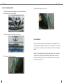
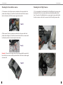
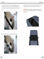
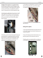
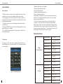
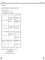
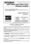
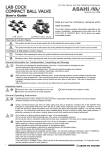
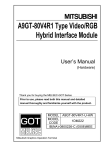
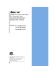
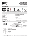
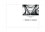
User Instructions
Welcome to the use of the Birdview Parking System. Please read the user
manual carefully before using the Birdview Parking System. Please
note the sketches shown in the instructions are illustrative only and please refer
to full-scale production for actual use.
1.Safety Protection
In order to insure the safety use of this product, read the following required items:
1) This product is driving auxiliary equipment only and therefore can not replace
the actual observation of eyes. It may result in serious traffic accident if over
depending on the system.
2) The camera viewing angle is relatively large, therefore, this product cannot
fully display actual conditions. Be careful always and use it to be familiar with
the product.
3) Don't operate this system while driving at high speed in order to avoid distractions. (Please be careful at higt speed driving , the operation of this system may
result in serious trafficc accident, to avoid accidents in the speed of more than
5MPH. Do not operate the system while driving).
4) Do not replace the wire harness or fuse without professional personnel
instructions, otherwise, it may damage the system or result in other safety issues.
5) Don't place the product in humid or wet areas in order to avoid short circuit that
can lead to electric shock and fire.
6) Please install the product in designated places. In case of system abnormality,
take it to professional place for maintenance. If installation or maintenance is done
by an unprofessional technician, which can lead results in damages, and will be
void the warranty.
7) Please apply the system under working voltage.
8)To avoid electromagnetic interference or incompatible features, please stop
using the equipment.
9)The output voltage of the host is 3.3V, only to serve the camera. Please don't
add or substitute incompatible parts or equipments.
10)Non-standard or undesignated adapter connectors with power may destroy the
camera, therefore, do not apply equipped camera to other devices.
1
User Instructions
2. Product Description
This Birdview Parking System is an intelligent electronic vehicle product,
which collects 4 images around automobiles. After image processing units
and a series of intelligent algorithm processing, the panorama overhead view
of a vehicle is shown on the screen, which displays relevant locations and
around conditions directly. The system, to a great extend, expands drivers'
environment perceptions, so they can deal with parking and narrow road
entrances, and barriers easily with decreased traffic accidents such as
scraping cars.
BILL OF MATERIAL
(1) Control Box
(2) Accessories and cables
7
2
User Instructions
User Instructions
1. Left turn/ Right Turn/ Reverse signal cable power connector x1
2. Power connector (ACC/ BATT/ GND) x1
3. Camera signal extension cable x4
4. IR receiver x1
5. Composite video signal cable (Camera video input/ Video output/ IR) x1
6. IR Remote control x1
7. Debugging(calibration) mat x1
Connection Diagram
(3) Front Camera x1, Rear Camera x1
Front
camera
Left view
Right view camera
ra
me
view ca
Rear view camera
(3) Left Camera x1, Right Camera x1
right
turn
left
turn
IR
GND
VBAT+
BACK_IN
ACC
Remote receiver
Videot-B
Camera signal
extension cables
Cameras
Video-CTRL
(Connect with any monitor or DVD)
3
right/left turn
signal cable
4
User Instructions
Camera Mounting Position
User Instructions
(4) Right camera: Right side view mirror
(1) Front view camera: On the depot logo or on top of the front license
plate depending on the vehicle molding
(2) Rear view camera: On top of the rear license plate.
Unit Installation
First, please place the products directly under the driver seat, and gather the front/
rear/ left/ right camera signal extension cables to where the product is. Then connect
the camera signal extension cables onto the products where front/ rear/ left/ right are
marked.
(3) Left camera: Left side view mirror
5
Reminder: When installing the left and right cameras, the side view mirrors must
first be removed in order to run the camera cables inside the side view mirrors.
Connect the other end of the cables to the extension cable then run the extension
cable to the main control box.
6
User Instructions
User Instructions
Mounting the Front and Rear cameras
Mounting the Left/ Right Cameras
(1) Front camera: after the front camera is positioned, run the camera cable to the
position shown in Figure(3),(1), and then connect the male end of the front camera
cable to the female end of the front camera signal extension cable
(1) It is recommended to first disassemble the Left and Right side view mirrors, and
also disassemble the side view mirror and electronic directional modules within
them. Then run the Left and Right side view camera signal extension cables within
the sideview mirrors so that it can be connected to the left and right cameras later.
.
(2) Rear camera: After the rear camera is positioned, run the camera cable to the
position shown in Figure(3),(2), and then connect male end of the rear camera cable
to the female end of the rear camera singal extension cable.
The male end of the signal extension
cable runs along with the wires of the
electronic side view mirrors. Run the
cable to where the product unit is
positioned.
Reminder: Please refer to the figure below for the wiring method; the purple solid
line is the front/ rear camera, and the green dotted line is the front/rear camera signal
extension cable.
The female end of the signal extension
cable is left within the side view
mirror.
7
8
User Instructions
(2) Use the marker to aim at the hollow camera hole and mark the center of the
camera hole on the side view mirror. And then use the included drill to aim at the
center point that was just marked to drill holes on the original Left/ Right side view
mirrors.
User Instructions
(4) Finally, connect the male end of the camera cable to the female end of the camera
signal extension cable to complete the connection of the side view mirror.
Reminder: Please refer to the figure below for the wiring method; the purple solid
line is the Left/ Right cameras, and the green dotted lines are the camera signal
extension cables.
(3) Then please place the camera to the mounting hole that was drilled.
9
10
User Instructions
Installing the left turn/ right turn/ reverse signal switch cables
In order for the products to immediately switch to the corresponding screen while
the vehicle is left/ right turning or reversing, this signal cable must be installed with
the vehicle’s own left turn/ right turn/ reverse signal light cable to complete this
function. The following example will use the right turn signal light as an example.
User Instructions
(3) After confirmation, use electrical insulation tape to connect the green and white
cable (right turn light signal cable) with the orange cable (left turn/ right turn/
reverse signal cable) to complete the wiring.
(1) First, find the right turn signal light cable and the color of the cable. It is usually
behind the light shell seat in the trunk and it is easier to find the right turn light
signal cable here. In the example in the figure below, the right turn light signal
cable is a green and white cable. (the color of the cables differs according to
different car and models)
(4) The wiring method for the left turn/ reverse signal cables are the same as the
method described above.
Checking after the completion
(1) Turn on the right turn light signal and then check if the right turn indicator comes
on. Check whether the panoramic screen has switched to the right camera screen.
(As shown in the figure below).
(2) Then find the green and white cable (right turn light signal cable) from the signal
box trench below the driver’s seat, and then connect the positive end of the light
bulb (green and white) to it, and the black cable of the light signal to the ground.
Finally, turn on the right turn light signal and see if the light bulb comes on to
confirm whether the correct right turn light signal cable was found.
(2) Turn on the left turn light signal, and check if the left turn indicator comes on
and whether the panoramic screen has switched to the left camera screen.
(3) Switch the gear to the reverse position and check if the reverse indicator comes
on. Check whether the panoramic screen has switched to the rear camera screen.
camera
11
12
User Instructions
User Instructions
Setup and Calibration
Display Interface
By using masking tape, tape a rectangle around the vehicle like the diagram
shown below. The front line should be taped 9.8 inches away from the front
bumper. The rear line should be taped 3.9 inches saway from the rear bumper.
The left and right side taped should be 2 inches away from the wheel.
The Birdview Parking System video output can be connected to independent LCD
monitor. The Birdview Parking System view illustrations: when the system starts,
images can be shown as figure4.1. The panorama view mode is made of overhead
display and single camera display area. The former picture shows the front, back,
left and right side of the vehicle body, scopes of which is around 78.7, 157.5, 98.4,
98.4 inch.
Lay Down four debugging mats
59inch
The front mat is lined up to the left side of the rectangle lines
The rear mat is lined up to the right side of the rectangle lines
The left and right mats are lined starting from 59 inches from the front rectangle
line. (See below digram)
fig4. 1 Panorama effects
Within single camera display area, the up-right sign indicates which camera was
used to show the image as shown in figure4.2.
Calibration
59inch
Press the menu key on the remote control
You will be prompted to enter a passkey. Key in the passkey 198678, then press
enter.
Select “Mosaic” and enter only the length and width of the car.
Press “Okay” key to start auto calibration and wait for it to finish.
193 inch
70.9 inch
59
13
inch
fig 4. 2 Front rear sign
The displayed effects may be influenced by the following situations:
1. Camera is exposed to the direct sun light.
2. Rain
3. Camera interface freezes or lens is spotted with mud, dust, or snow.
4. Under weak light environment.
14
User Instructions
User Instructions
System Function
General Function
1. When the car starts, the system will stay in the standby mode. It turns on when
you put the car in reverse gear or by manually pressing the power button.
2. After engaging in revers, if the car does not stay in reverse gear, and the user
does not operate or press power button within 30 seconds, the host will enter back
to standby mode automatically.
3. When the car is put in reverse mode, the display will automatically show the
rear camera video.
4. Pressing the “OPTIONS” key on the remote will flip through the four viewing
modes; Front, Rear, Left, and Right.
5. To view the side camera automatically, turn on the right or left blinker to view
the corresponding camera.
1. Brightness: adjust output screen brightness.
2. Contrast: adjust output image contrast
3. Hue: adjust output image hue
4. Saturation: adjust output image saturation
5. Skins: choose interface appearance
6. System standby: When the gear is not set in reverse mode with no operations,
the host will enter standby mode after idle for some time. You can set the idle
time before it enters standby mode.
7. Field of view: default visual range of the system is 2in (front), 4in(back),
2.5in(right). User can increase or decrease the range based on these figures.
When you choose “smaller”, the visual range will decrease 10% compared with
the default distance, and the proportion of vehicle body will expand in picture: for
the same reason when you choose “larger”. The visual range will increase by 10%
and the proportion of vehicle body will reduce in the picture.
Product Specification
User Functions
User settings, press “OK” on the remote to confirm. Then press direction key to
switch or change values. Press remote controller “OK” key, then enter users menu
as show in Figure 5.1
Image
Processing Unit
fig 5.1 Users setting menu
15
Camera
Working Voltager
DC 7~36V
Working Current
≤400mA( DC 7~36 V)
Quiescent Current
≤1mA
Average Power
≤4.8W
Working Temperature
-30°C~85°C
Storage Temperature
-40°C~105°C
Working Humidity
10%~95%
Video Input Format
PAL/NTSC
Video Output Format
PAL/NTSC
Working Current
≤50mA( DC 3.3 V)
Quiescent Current
≤1mA
Average Power
≤0.6W
Working Temperature
-40°C~105°C
Working Humidity
10%~95%
Video Output Format
PAL/NTSC
16
User Instructions
User Instructions
Maintenance
1. Please keep the camera surface clean. Use soft cloth or paper towel to wipe the
surface of the lens or rinse with water. Use low water pressure. Avoid using high
pressure spray to wash the camera.
2. Avoid scratching and abrasive objects near the lens.
3. For basic troubleshooting guides, see the below table.
circumstance
Fuzzy picture or deformation
reason analysis
1.the camera surface attached
snow、mud、drop of water、 and dirt
2. Camera surface freezes
3.Drive in heavy rains or foggy
weather.
4. Camera scratch
5. Camera damaged
Incomplete pictures
1.Camera wire harness falls off
2.Camera wire harness is damaged
3.Camera is damaged
No image output
1. Video signal line、output control
line or power line fall off
2. Original car screen is damaged
3. Fuse links
Unbootable in reverse gear
Other questions
Reverse signal falls off
Elimination method
1. Clean the camera
2. Apply warm salty water to unfreeze
3. Pay attention to use it in rainy or
foggy days
4. Contact professional maintenance
point to replace the camera.
5. Contact professional maintenance
point to replace the camera.
Please contact professional
maintenance point to check the
camera or replace the camera
1. Contact professional maintenance
point
2. Check if original car screen is
damaged
3. If fault-free original car screen is
free, please contact professional
maintenance poin
Please contact professional
maintenance point
Please contact professional
maintenance point
Should you have any trouble or need technical assistance, feel free to call us.
For U.S. 888-941-3060
For International 714-446-0543
Tech Support Email: [email protected]
17
18