1
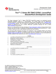
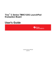
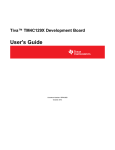
Stellaris® LM4F120 LaunchPad Evaluation Kit BoosterPack Development Guide Build your own BoosterPack and take advantage of Texas Instruments’ web site to help promote it! From sharing a new idea or project, to designing, manufacturing, and selling your own BoosterPack kit, TI offers a variety of avenues for you to reach potential customers with your solutions. www.ti.com/stellaris-launchpad EK-LM4F1 20XL-DG-01 SPMU288 Copyrig ht © 201 2 Te xas In strumen ts Stellaris LaunchPad BoosterPack Design Guide Copyright Copyright © 2012 Texas Instruments, Inc. All rights reserved. Stellaris and StellarisWare are registered trademarks of Texas Instruments. ARM and Thumb are registered trademarks, and Cortex is a trademark of ARM Limited. Other names and brands may be claimed as the property of others. Texas Instruments 108 Wild Basin, Suite 350 Austin, TX 78746 http://www.ti.com/stellaris August 24, 2012 2 Stellaris LaunchPad BoosterPack Development Guide Table of Contents Chapter 1: Stellaris® LaunchPad and BoosterPack Expansion Concept and Overview........................... 6 BoosterPack Functional Interface....................................................................................................................... 7 BoosterPack XL Functional Interface ................................................................................................................. 9 LaunchPad Power Interface ............................................................................................................................. 10 Special Consideration for Shared Pins ............................................................................................................. 11 Stellaris LaunchPad Dimensions and Mating ................................................................................................... 11 BoosterPack Design Guidelines ....................................................................................................................... 12 Appendix A: Schematics................................................................................................................................ 13 Appendix B: References ................................................................................................................................ 17 August 24, 2012 3 Stellaris LaunchPad BoosterPack Development Guide List of Figures Figure 1-1. Stellaris® LM4F120 LaunchPad Evaluation Board ......................................................................... 7 August 24, 2012 4 Stellaris LaunchPad BoosterPack Development Guide List of Tables Table 1-1. Table 1-2. Table 1-3. Table 1-4. Table 1-5. Table 1-6. LaunchPad BoosterPack Compatibility Summary........................................................................... 6 J1Connector .................................................................................................................................... 8 J2 Connector ................................................................................................................................... 8 J3 Connector ................................................................................................................................... 9 J4 Connector ................................................................................................................................... 9 Stellaris® LaunchPad Jumper List ................................................................................................ 11 August 24, 2012 5 C H A P T E R 1 Stellaris® LaunchPad and BoosterPack Expansion Concept and Overview The Texas Instruments’ Stellaris® LM4F120 LaunchPad concept is an extremely low-cost, expandable evaluation system for TI microcontrollers. This concept began with the tremendously successful MSP430™ LaunchPad which introduced a large number of engineers to the TI MSP430 family of microcontrollers. The TI Stellaris microcontroller family is expanding on that success by introducing the Stellaris® LM4F120 LaunchPad featuring the Stellaris ARM® Cortex™-M4F LM4F120H5QRFIG microcontroller. A Stellaris LaunchPad consists of a target microcontroller, an in-circuit debug interface (ICDI) such as JTAG, a regulated power supply, a minimal microcontroller support circuit, a user interface, and a set of expansion headers. The expansion headers are referred to as the BoosterPack interface. A BoosterPack is an expansion card designed for this interface. This interface provides a mechanism for developers to easily extend the Stellaris LaunchPad with application- and user-specific functions. The Stellaris LaunchPad provides a BoosterPack interface that is compatible with the MSP430 LaunchPad. In addition, the Stellaris LaunchPad provides access to additional Stellaris functionality through an extended BoosterPack interface called the BoosterPack XL Interface. BoosterPack interfaces with highly similar functionality for expansion will be available for the Stellaris LaunchPad, in addition to microcontroller-family-specific functionality available on a BoosterPack XL Interface for additional options. Table 1-1 provides a summary of BoosterPack interface compatibility. Table 1-1. LaunchPad BoosterPack Compatibility Summary Compatible with... LaunchPad BoosterPack Interface BoosterPack XL Interface Stellaris LaunchPad Yes Yes MSP430 LaunchPad Yes No Other TI LaunchPads Yes No This development guide provides necessary design information for developers who want to create BoosterPacks that extend the functionality of the Stellaris® LaunchPad using either the original BoosterPack or the BoosterPack XL Interface. Figure 1-1 on page 7 shows a photo of the Stellaris® LaunchPad. August 24, 2012 6 Stellaris LaunchPad BoosterPack Development Guide Figure 1-1. Stellaris® LM4F120 LaunchPad Evaluation Board BoosterPack Functional Interface The Stellaris® LaunchPad's BoosterPack Interface provides compatibility with the original MSP430 LaunchPad's BoosterPack interface. This interface consists of the outer 10 pin headers. The pins are spaced 0.10-inch apart with the two headers located 1.8 inches apart. Table 1-2, ”J1Connector” on page 8 and Table 1-3, ”J2 Connector” on page 8 provide information for which Stellaris microcontroller peripherals are routed to each of the interface pins. The J1 connector is located on the far left side of the Stellaris LaunchPad. The J2 connector is located on the far right side of the Stellaris LaunchPad. Software is used to configure the LM4F120 pin for one of the functions found in the table. Highlighted functions indicate configuration for compatibility with the MSP430 LaunchPad. August 24, 2012 7 Stellaris LaunchPad BoosterPack Development Guide Table 1-2. J1Connector GPIOPCTL Register Setting J1 Pin GPIO Stellaris Pin GPIOAMSEL 1 2 3 7 8 9 14 3.3 V 1.01 1.02 PB5 57 AIN11 - SSI2Fss - T1CCP1 CAN0Tx - - 1.03 PB0 45 - U1Rx - - T2CCP0 - - - 1.04 PB1 46 - U1Tx - - T2CCP1 - - - 1.05 PE4 59 AIN9 U5Rx - I2C2SCL - CAN0Rx - - 1.06 PE5 60 AIN8 U5Tx - I2C2SDA - CAN0Tx - - 1.07 PB4 58 AIN10 - SSI2Clk - T1CCP0 CAN0Rx - - 1.08 PA5 22 - - SSI0Tx - - - - - 1.09 PA6 23 - - - I2C1SCL - - - - 1.10 PA7 24 - - - I2C1SDA - - - - Table 1-3. J2 Connector GPIOPCTL Register Setting J2 Pin GPIO Stellaris Pin GPIOAMSEL 1 2 3 7 8 9 14 GND 2.01 2.02 PB2 47 - - - I2C0SCL T3CCP0 - - - 2.03 PE0 9 AIN3 U7Rx - - - - - - 2.04a PF0 28 - U1RTS SSI1Rx CAN0Rx T0CCP0 NMI C0o - RESET 2.05 2.06b PB7 4 - - SSI2Tx - T0CCP1 - - - 2.07c PB6 1 - - SSI2Rx - T0CCP0 - - - 2.08 PA4 21 - - SSI0Rx - - - - - 2.09 PA3 20 - - SSI0Fss - - - - - 2.10 PA2 19 - - SSI0Clk - - - - - a. Not recommended for BoosterPack use. J2.04 is a TEST pin on the MSP430 LaunchPad. This signal tied to on-board function via 0-Ω resistor. b. J2.06 (PB7) is also connected via 0-Ω resistor to J3.04 (PD1) to provide MSP430 LaunchPad Compatible I2C SDA Signal. c. J2.07 (PB6) is also connected via 0-Ω resistor to J3.03 (PD0) to provide MSP430 LaunchPad Compatible I2C SCL Signal August 24, 2012 8 Stellaris LaunchPad BoosterPack Development Guide BoosterPack XL Functional Interface The BoosterPack XL Interface consists of the J1 and J2 connectors as well as the inner 10-pin headers spaced 1.6 inches apart directly inside of the MSP430 LaunchPad-compatible BoosterPack interface headers. The pins are spaced on 0.10-inch centers. These inner 10-pin headers (connectors J3 and J4) are not intended to be compatible with other TI LaunchPads or LaunchPad XL's. This is a Stellaris-only interface. TI recommends that LaunchPads provide analog functions on the left side of the BoosterPack XL interface and timer or PWM functions on the right side of the BoosterPack XL interface. Stellaris conforms to these recommendations. No effort has been made to make this interface compatible with any other LaunchPad. Table 1-4 and Table 1-5 show which Stellaris peripherals are routed to each pin of the Stellaris-only BoosterPack XL Interface pins. J3 is the inner left BoosterPack XL Interface header. J4 is the inner right BoosterPack XL Interface header. Software is used to configure the LMF4120 pin for one of the functions found in the table. Table 1-4. J3 Connector GPIOPCTL Register Setting J3 Pin GPIO Stellaris Pin GPIOAMSEL 1 2 3.01 5.0V 3.02 GND 3 7 8 9 14 3.03 PD0 61 AIN7 SSI3Clk SSI1Clk I2C3SCL WT2CCP0 - - - 3.04 PD1 62 AIN6 SSI3Fss SSI1Fss I2C3SDA WT2CCP1 - - - 3.05 PD2 63 AIN5 SSI3Rx SSI1Rx - WT3CCP0 - - - 3.06 PD3 64 AIN4 SSI3Tx SSI1Tx - WT3CCP1 - - - 3.07 PE1 8 AIN2 U7Tx - - - - - - 3.08 PE2 7 AIN1 - - - - - - - 3.09 PE3 6 AIN0 - - - - - - - 3.10a PF1 29 - U1CTS SSI1Tx - T0CCP1 - C1o TRD1 a. Not recommended for BoosterPack use. This signal tied to on-board function via 0-Ω resistor. Table 1-5. J4 Connector GPIOPCTL Register Setting J4 Pin GPIO Stellaris Pin GPIOAMSEL 1 2 3 7 8 9 14 4.01a PF2 30 - - SSI1Clk - T1CCP0 - - TRD0 4.02a PF3 31 - - SSI1Fss CAN0Tx T1CCP1 - - TRCL K 4.03 PB3 48 - - - I2C0SDA T3CCP1 - - - 4.04 PC4 16 C1- U4Rx U1Rx - WT0CCP0 U1RTS - - 4.05 PC5 15 C1+ U4Tx U1Tx - WT0CCP1 U1CTS - - 4.06 PC6 14 C0+ U3Rx - - WT1CCP0 - - - August 24, 2012 9 Stellaris LaunchPad BoosterPack Development Guide Table 1-5. J4 Connector (Continued) GPIOPCTL Register Setting J4 Pin GPIO Stellaris Pin GPIOAMSEL 1 2 3 7 8 9 14 4.07 PC7 13 C0- U3Tx - - WT1CCP1 - - - 4.08 PD6 53 - U2Rx - - WT5CCP0 - - - 4.09 PD7 10 - U2Tx - - WT5CCP1 NMI - - 4.10a PF4 5 - - - - T2CCP0 - - - a. Not recommended for BoosterPack use. This signal tied to on-board function via 0-Ω resistor. LaunchPad Power Interface The Stellaris LaunchPad has provisions to provide power to a BoosterPack through either the BoosterPack interface or the BoosterPack XL Interface. The configuration of power and ground pins on both of these interfaces must be consistent across LaunchPads from all TI microcontroller families. The Stellaris LaunchPad draws power from either of the on-board USB interfaces as selected by the power switch in the top left corner of the board. Typically, the USB connection provides 500 milliamps at 5 V to the Stellaris LaunchPad. The selected USB power source is made directly available to the BoosterPack XL Interface on the J3.01 pin. This is a direct connection with only small decoupling capacitors provided on the Stellaris LaunchPad. All LaunchPads, including the Stellaris LaunchPad, also provide a 3.3-V supply on pin J1.01 of the BoosterPack interface. On the Stellaris LaunchPad, this is sourced by a TPS73633 LDO voltage regulator which converts the selected 5-V USB power to 3.3 V. The regulator is capable of sourcing 400 milliamps at 3.3 V. This 3.3-V supply is shared between the BoosterPack interface, the in-circuit debug interface (ICDI), and the target microcontroller. Therefore, under normal circumstances, about 300 to 350 milliamps are available to the BoosterPack interface. Detailed power management is left to the BoosterPack developer who must also manage the application to be run on the target microcontroller. The Stellaris LaunchPad can be powered through an external supply on a BoosterPack. If providing power to the Stellaris LaunchPad from a BoosterPack, move the power select switch to select an unused USB connection to prevent power bus contention between the BoosterPack and the USB connection. Power may be supplied to either the 3.3 V or the 5.0-V system but not both. Providing external power to both 5 V and 3.3 V would result in a contention between the external power supplies and the Stellaris LaunchPad's voltage regulator. Providing only 3.3 V will result in some lost functionality such as the on-board LED’s. It may also result in reverse current leakage through the on-board voltage regulator. Therefore, it is recommended if providing power externally to use either the existing USB connections or an external 5-V supply from a BoosterPack. Ground connections are available on pins J2.01 and J3.02. These provide a ground connection for both the BoosterPack interface and the BoosterPack XL Interface respectively. Additional power and ground pins are available through labeled pins located in the extreme lower corners of the Stellaris LaunchPad. These are connected to the same 3.3 V, 5 V, and ground connections as the pins on the BoosterPack interface and the BoosterPack XL Interface. August 24, 2012 10 Stellaris LaunchPad BoosterPack Development Guide Special Consideration for Shared Pins To provide compatibility with the MSP430 LaunchPad's BoosterPack interface and to provide a maximum number of signals to the BoosterPack interface and BoosterPack XL Interface, it was necessary to route some signals to more than one pin. In addition, certain on-board functions such as the button and LED signals are available on the BoosterPack interface and BoosterPack XL Interface. A 0-Ω jumper resistor was installed for signals that are used for more than one purpose or routed to more than one GPIO. Removal of this jumper disconnects the functions. All jumpers are installed by default. A listing of these jumpers and their use is provided in Table 1-6. Table 1-6. Stellaris® LaunchPad Jumper List Resistor Primary Function Alternate Function Comments R1 Right User Switch J2.04 Test pin on MSP430 LaunchPad. This connection along with R13 provides Hibernate wake to BoosterPack interface R2 Red LED To PF1 and J3.10 If removed: allows extra GPIO to the BoosterPack XL interface. If installed (default): allows booster pack to drive LED or sense LED state. Also provides Embedded Trace signal TRD1. R8 Hibernate Wake To PF0 and J2.04 via R1 Allows user switch 2 to wake device from hibernate. Also ties wake to J2.04 to allow BoosterPack to wake Stellaris LaunchPad from Hibernate. R9 PB6 SSI2 TX on J2.07 PD0 I2C SCL on J2.07 Routes I2C from PD0 to J2.07 for MSP430 Stellaris LaunchPad compatibility. If using PD0 or PB6, the unused GPIO must be configured as an input or R9 removed. R10 PB7 SSI2 RX on J2.06 PD1 I2C SDA on J2.06 Routes I2C from PD1 to J2.06 for MSP430 Stellaris LaunchPad compatibility. If using PD1 or PB7, the unused GPIO must be configured as an input or R9 removed. R11 Blue LED To PF2 and J4.01 If removed: allows extra GPIO to the BoosterPack XL interface. If installed (default): allows BoosterPack to drive LED or sense LED state. Also provides Embedded Trace signal TRD0. R12 Green LED To PF3 and J4.02 If removed: allows extra GPIO to the BoosterPack XL interface. If installed (default): allows BoosterPack to drive LED or sense LED state. Also provides Embedded Trace signal TRDCLK. R13 Left User Switch To PF4 and J4.10 If removed: allows extra GPIO to the BoosterPack XL interface. If installed (default): allows BoosterPack to simulate switch press or sense switch state. Stellaris LaunchPad Dimensions and Mating Figure 1-1 on page 7 shows a dimensional drawing of the Stellaris LaunchPad. J1 and J2 are 1.8 inches apart and constitute the BoosterPack interface. J3 and J4 are 1.6 inches apart and constitute the BoosterPack XL Interface. Other major board signals are available on unpopulated headers on a 0.1 inch grid. Dimensions to these signals are provided for convenience. These signals are subject to change or move across revisions of the Stellaris LaunchPad or future LaunchPads. It is recommended that BoosterPacks use only the BoosterPack interface and BoosterPack XL Interface. Use of other pins and signals is acceptable but these pins and signals can change at any time. August 24, 2012 11 Stellaris LaunchPad BoosterPack Development Guide BoosterPack Design Guidelines Follow these guidelines when designing your BoosterPack: BoosterPacks should not extend more than 0.350 inches above the center of the top BoosterPack interface pin. BoosterPacks should not extend more than 0.150 inches below the center of the bottom pin of the BoosterPack interface. Note: BoosterPacks that extend more than 0.150 inches below the center of the bottom pin will partially cover the Stellaris LaunchPad user switches which can result in lost user access to those user inputs. BoosterPacks are not restricted in width and may extend as much as desired left and right of the Stellaris LaunchPad. For BoosterPacks with RF antennas, place the antenna to the left or right of the Stellaris LaunchPad for minimal interference and signal attenuation. The BoosterPack interface does not provide any means of keying or alignment guidance. It is recommended that visual cues be provided on the BoosterPack to assist user in proper orientation of the BoosterPack. If possible, design the BoosterPack so that incorrect mating to a Stellaris LaunchPad will not damage the BoosterPack. August 24, 2012 12 A P P E N D I X A Schematics This section contains the schematics for the Stellaris® LaunchPad evaluation board: Microcontroller, USB, Expansion, Buttons, and LED on page 14 Power Management on page 15 Stellaris In-Circuit Debug Interface (ICDI) on page 16 August 24, 2012 13 Microcontroller, USB, Expansion, Buttons, and LED 9 8 7 6 59 60 PF0 PF1 PF2 PF3 PF4 PE0 PE1 PE2 PE3 PE4 PE5 VB 1 D+ D2 3 G PD0 PD1 PD2 PD3 0 9 8 ID 61 62 63 64 43 44 53 10 J9 CON-USB-MICROB 5 PD0 PD1 PD2 PD3 PD4 PD5 PD6 PD7 PB0 PB1 PB2 PB3 PB4 PB5 PB6 PB7 7 6 R14 +USB_VBUS +USB_VBUS USB_DM USB_DP 28 29 30 31 5 PD6 PD7 PF0 PF1 PF2 PF3 PF4 10k PE0 PE1 PE2 PE3 PE4 PE5 PC0 PC1 PC2 PC3 PC4 PC5 PC6 PC7 GPIO 45 46 47 48 58 57 1 4 R6 PC4 PC5 PC6 PC7 52 51 50 49 16 15 14 13 DEBUG_PC0/TCK/SWCLK DEBUG_PC1/TMS/SWDIO DEBUG_PC2/TDI DEBUG_PC3/TDO/SWO PB0 PB1 PB2 PB3 PB4 PB5 PB6 PB7 0 USB_DP R15 USB_DM J1 and J2 provide compatability with 1M PA2 PA3 PA4 PA5 PA6 PA7 PA0 PA1 PA2 PA3 PA4 PA5 PA6 PA7 4 U1-A 17 18 19 20 21 22 23 24 PA0/U0RX_VCP_TXD PA1/U0TX_VCP_RXD GPIO R7 DEBUG/VCOM Booster Packs designed for MSP430 Launchpad Used for VBUS detection when J3 and J4 sit 100 mils inside J1 and J2 to provide configured as a self-powered USB Device extended functions specific to this board. LM4F120 See the board user manual for complete table of pin mux functions GPIO 0 0 0 0 0 R1 R2 R11 R12 R13 +3.3V USR_SW2 LED_R LED_B LED_G USR_SW1 J1 PD0 PD1 PB6 R9 0 PB7 R10 J2 1 2 3 4 5 6 7 8 9 10 0 PB5 PB0 PB1 PE4 PE5 PB4 PA5 PA6 PA7 1 2 3 4 5 6 7 8 9 10 PB2 PE0 PF0 PB7 PB6 PA4 PA3 PA2 TARGETRST CON_110_100 CON_110_100 +VBUS SW1 USR_SW1 J3 R3 C LED_R Q1 DTC114EET1G B E +VBUS SW2 USR_SW2 D1 R5 C LED_G 330 Q3 DTC114EET1G B 2 3 4 R G B A 1 RGB_LED_0404_COMA J4 1 2 3 4 5 6 7 8 9 10 330 PD0 PD1 PD2 PD3 PE1 PE2 PE3 PF1 PF2 PF3 PB3 PC4 PC5 PC6 PC7 PD6 PD7 PF4 1 2 3 4 5 6 7 8 9 10 CON_110_100 CON_110_100 R8 WAKE 330 E R4 C LED_B 330 Q2 DTC114EET1G B E DESIGNER REVISION DATE DGT 0.1 8/23/2012 TEXAS INSTRUMENTS STELLARIS R MICROCONTROLLERS PROJECT 108 WILD BASIN ROAD, SUITE 350 AUSTIN TX, 78746 Stellaris Launchpad DESCRIPTION www.ti.com/stellaris Microcontroller, USB, Expansion, Buttons and LED FILENAME EK-LM4F120XL Rev A.sch PART NO. EK-LM4F120XL SHEET 1 OF 3 Power Management +MCU_PWR RESET R28 10k H20 H24 and H25 installed as a single 1x2 RESET +USB_VBUS header on 100 mil center with jumper TARGETRST H18 Power Select C13 0.1uF OMIT +VBUS SW3 U1-B RESET WAKE 41 OSC1 40 OSC0 6 5 34 XOSC0 35 GNDX 36 XOSC1 C28 24pF C29 24pF 0 R26 Y2 16MHz 3 C31 10pF +3.3V +VBUS +3.3V 400mA Regulator H22 32.768Khz Y1 VDDA 33 +3.3V 0 R30 OMIT HIB 37 2 11 VDD 26 VDD 42 VDD 54 VDD GNDA 12 GND 27 GND 39 GND 55 GND C32 10pF HIB VBAT 32 H1 38 2 3 4 H25 WAKE 1 H17 H23 +MCU_PWR H24 H21 25 VDDC 56 VDDC LM4F120 C3 C4 C5 C6 C8 C7 0.01uF 0.1uF 0.01uF 0.1uF 0.01uF 1.0uF H2 H19 1M R31 +ICDI_VBUS C10 0.1uF +MCU_VDDC C11 0.1uF C12 C22 2.2uF 1.0uF U8 TPS73633DRB C18 0.01uF Green 1.0uF 3 9 4 C14 1 R27 NR PAD EN GND 330 OUT IN 5 D4 8 H11 H13 H12 H10 +VBUS +3.3V R17 10k D2 TLV803 RESET 2 3 VDD GND 1 A1 3 K A2 TARGETRST ICDI_RST U4 DESIGNER REVISION DATE DGT 0.1 8/23/2012 TEXAS INSTRUMENTS STELLARIS R MICROCONTROLLERS PROJECT 108 WILD BASIN ROAD, SUITE 350 AUSTIN TX, 78746 Stellaris Launchpad DESCRIPTION www.ti.com/stellaris Power Management FILENAME EK-LM4F120XL Rev A.sch PART NO. EK-LM4F120XL SHEET 2 OF 3 Stellaris In-Circuit Debug Interface (ICDI) PA1/U0TX_VCP_RXD PA0/U0RX_VCP_TXD +MCU_PWR Stellaris In-Circuit Debug Interface (ICDI) DEBUG/VCOM +3.3V 52 51 50 49 16 15 14 13 R22 10k 9 8 7 6 59 60 ICDI_TCK ICDI_TMS ICDI_TDI ICDI_TDO PC0 PC1 PC2 PC3 PC4 PC5 PC6 PC7 PD0 PD1 PD2 PD3 PD4 PD5 PD6 PD7 PE0 PE1 PE2 PE3 PE4 PE5 PF0 PF1 PF2 PF3 PF4 45 46 47 48 58 57 1 4 61 62 63 64 43 44 53 10 28 29 30 31 5 R24 330 VB 1 D- 2 DEBUG_PC3/TDO/SWO D+ 3 ID 4 DEBUG_PC1/TMS/SWDIO DEBUG_PC0/TCK/SWCLK CON-USB-MICROB J11 H14 EXTDBG +3.3V PB0 PB1 PB2 PB3 PB4 PB5 PB6 PB7 6 7 TARGETRST PA0 PA1 PA2 PA3 PA4 PA5 PA6 PA7 0 R16 G 5 8 9 17 18 19 20 21 22 23 24 DEBUG_PC0/TCK/SWCLK DEBUG_PC1/TMS/SWDIO DEBUG_PC3/TDO/SWO DEBUG_PC2/TDI R21 10k +ICDI_VBUS U2-A R23 10k H15 R18 10k LM4F120 +3.3V R19 10k ICDI_RST C34 0.1uF OMIT ICDI JTAG +3.3V U2-B 38 RESET WAKE 34 XOSC0 35 GNDX 36 XOSC1 0 R20 41 OSC1 40 OSC0 Y5 16MHz 3 C25 10pF C26 10pF HIB VBAT VDDA ICDI_TCK 37 ICDI_TMS +3.3V 5 4 3 2 1 6 7 8 9 10 ICDI_TDO ICDI_TDI ICDI_RST 2 11 VDD 26 VDD 42 VDD 54 VDD GNDA 12 GND 27 GND 39 GND 55 GND J5 32 33 TC2050-IDC-NL C15 C17 C19 C20 C21 C1 0.01uF 0.1uF 0.01uF 0.1uF 0.01uF 1.0uF 25 VDDC 56 VDDC LM4F120 C23 0.1uF C24 0.1uF C2 1.0uF C9 2.2uF DESIGNER REVISION DATE DGT 0.1 8/23/2012 TEXAS INSTRUMENTS STELLARIS R MICROCONTROLLERS PROJECT 108 WILD BASIN ROAD, SUITE 350 AUSTIN TX, 78746 Stellaris Launchpad DESCRIPTION www.ti.com/stellaris SStellaris In Circuit Debug Interface FILENAME EK-LM4F120XL Rev A.sch PART NO. EK-LM4F120XL SHEET 3 OF 3 A P P E N D I X B References In addition to this document, the following references are included on the Stellaris LaunchPad Evaluation Kit CD and are also available for download at www.ti.com. Stellaris LaunchPad (EK-LM4120XL) User's Manual, publication EK-LM4F120-XL Stellaris LM4F120H5QRFIG Microcontroller Data Sheet, publication DS-LM4F120H5QR StellarisWare® Driver Library StellarisWare® Driver Library User’s Manual, publication SW-DRL-UG Information on development tool being used: August 24, 2012 Texas Instruments’ Code Composer Studio™ IDE web site, www.ti.com/ccs 17 IMPORTANT NOTICE Texas Instruments Incorporated and its subsidiaries (TI) reserve the right to make corrections, enhancements, improvements and other changes to its semiconductor products and services per JESD46C and to discontinue any product or service per JESD48B. Buyers should obtain the latest relevant information before placing orders and should verify that such information is current and complete. All semiconductor products (also referred to herein as “components”) are sold subject to TI’s terms and conditions of sale supplied at the time of order acknowledgment. TI warrants performance of its components to the specifications applicable at the time of sale, in accordance with the warranty in TI’s terms and conditions of sale of semiconductor products. Testing and other quality control techniques are used to the extent TI deems necessary to support this warranty. Except where mandated by applicable law, testing of all parameters of each component is not necessarily performed. TI assumes no liability for applications assistance or the design of Buyers’ products. Buyers are responsible for their products and applications using TI components. To minimize the risks associated with Buyers’ products and applications, Buyers should provide adequate design and operating safeguards. TI does not warrant or represent that any license, either express or implied, is granted under any patent right, copyright, mask work right, or other intellectual property right relating to any combination, machine, or process in which TI components or services are used. Information published by TI regarding third-party products or services does not constitute a license to use such products or services or a warranty or endorsement thereof. Use of such information may require a license from a third party under the patents or other intellectual property of the third party, or a license from TI under the patents or other intellectual property of TI. Reproduction of significant portions of TI information in TI data books or data sheets is permissible only if reproduction is without alteration and is accompanied by all associated warranties, conditions, limitations, and notices. TI is not responsible or liable for such altered documentation. Information of third parties may be subject to additional restrictions. Resale of TI components or services with statements different from or beyond the parameters stated by TI for that component or service voids all express and any implied warranties for the associated TI component or service and is an unfair and deceptive business practice. TI is not responsible or liable for any such statements. Buyer acknowledges and agrees that it is solely responsible for compliance with all legal, regulatory and safety-related requirements concerning its products, and any use of TI components in its applications, notwithstanding any applications-related information or support that may be provided by TI. Buyer represents and agrees that it has all the necessary expertise to create and implement safeguards which anticipate dangerous consequences of failures, monitor failures and their consequences, lessen the likelihood of failures that might cause harm and take appropriate remedial actions. Buyer will fully indemnify TI and its representatives against any damages arising out of the use of any TI components in safety-critical applications. In some cases, TI components may be promoted specifically to facilitate safety-related applications. With such components, TI’s goal is to help enable customers to design and create their own end-product solutions that meet applicable functional safety standards and requirements. Nonetheless, such components are subject to these terms. No TI components are authorized for use in FDA Class III (or similar life-critical medical equipment) unless authorized officers of the parties have executed a special agreement specifically governing such use. Only those TI components which TI has specifically designated as military grade or “enhanced plastic” are designed and intended for use in military/aerospace applications or environments. Buyer acknowledges and agrees that any military or aerospace use of TI components which have not been so designated is solely at the Buyer's risk, and that Buyer is solely responsible for compliance with all legal and regulatory requirements in connection with such use. TI has specifically designated certain components which meet ISO/TS16949 requirements, mainly for automotive use. Components which have not been so designated are neither designed nor intended for automotive use; and TI will not be responsible for any failure of such components to meet such requirements. Products Applications Audio www.ti.com/audio Automotive and Transportation www.ti.com/automotive Amplifiers amplifier.ti.com Communications and Telecom www.ti.com/communications Data Converters dataconverter.ti.com Computers and Peripherals www.ti.com/computers DLP® Products www.dlp.com Consumer Electronics www.ti.com/consumer-apps DSP dsp.ti.com Energy and Lighting www.ti.com/energy Clocks and Timers www.ti.com/clocks Industrial www.ti.com/industrial Interface interface.ti.com Medical www.ti.com/medical Logic logic.ti.com Security www.ti.com/security Power Mgmt power.ti.com Space, Avionics and Defense www.ti.com/space-avionics-defense Microcontrollers microcontroller.ti.com Video and Imaging www.ti.com/video RFID www.ti-rfid.com OMAP Mobile Processors www.ti.com/omap TI E2E Community e2e.ti.com Wireless Connectivity www.ti.com/wirelessconnectivity Mailing Address: Texas Instruments, Post Office Box 655303, Dallas, Texas 75265 Copyright © 2012, Texas Instruments Incorporated