1
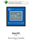
ELNet PFC Power Factor Controller Rev. 1.5 Table of Contents CHAPTER 1 - INTRODUCTION .................................. 3 1.1 1.2 1.3 1.4 1.5 1.6 About the ELNet PFC Power Factor Controller .... 3 How to use this manual ....................................................... 3 Safety Information .............................................................. 5 Warranty .............................................................................. 6 Your comments are welcome ............................................... 7 Disclaimer ............................................................................ 8 CHAPTER 2 — INSTALLATION ................................. 9 2.1 2.2 2.3 2.4 Contents of packaging ....................................................... 10 Mechanical mounting ........................................................ 11 Electrical Wiring Diagrams .............................................. 13 Test Relays Screen ............................................................. 16 CHAPTER 3 – Power Factor Controller .................. 18 3.1 3.2 3.3 3.4 General information. ......................................................... 18 Controller's Data Screen. .................................................. 19 Voltage, Current, Hz. ........................................................ 20 Power Factor, THD. ........................................................... 20 CHAPTER 4 - Power Factor Controller Settings .... 22 4.1 4.2 4.3 4.4 4.5 Single \ Three Phase modes. .............................................. 22 Transformers Ratio. .......................................................... 23 Vital Setting. ...................................................................... 25 Non-vital setting. ............................................................... 29 Working range settings. .................................................... 31 2 CHAPTER 1 - INTRODUCTION 1.1 About the ELNet PFC Power Factor Controller ELNet PFC - Power Factor Controller enables measurement of power factor and power factor correction by using up to 6 On/Off switching control of capacitor bank. ELNet PFC enables automatic identification of capacitors' size and its connection in various methods. The advanced LCD screen allows easily accessing basic electrical values screens such as voltage, current etc as well as all the information and the setting screens. 1.2 How to use this manual We at CONTROL APPLICATIONS Ltd, envisage this manual to be used by three types of people, i.e. the Installation Technician, the Senior Electrical Engineer and the end User. For this reason this manual is divided into chapters for ease of reference by each of these different people. There could be a situation where two of the above mentioned tasks can be combined, or in a rare instance one person could handle all three tasks. CHAPTER 1, Introduction, describes the ELNet PFC Power Factor Controller , its potential users, the readings it can provide and some of its features in brief. 3 CHAPTER 2, Installation, provides detailed instructions for unpacking, mechanical mounting, and electrical wiring up instructions for the Installation Technician. CHAPTER 3, Using the ELNet PFC Power Factor Controller, describes in detail front Panel, the functions of the control buttons, and the Lock Utility. CHAPTER 4, Parameter Configuration & Settings explains in detail the minimum parameters settings needed by the Senior Electrical Engineer to set up and configure the ELNet PFC Power Factor Controller . 4 1.3 Safety Information The purpose of this manual is to help you. Please read the instructions carefully before performing any installation and note any precautions. WARNING! Ensure that all incoming AC power and other power sources are turned off before performing any work on the ELNet PFC. Failure to do so may result in serious or even fatal injury and/or equipment damage. If the ELNet PFC is damaged in any way do NOT connect it to any power source. To prevent a potential fire or shock hazard, never expose the ELNet PFC to rain or moisture. 5 Keep the surrounding area free of dirt and clutter especially metal objects. Good housekeeping pays. Inspect the cables periodically for cracks, kinks or any other signs of wear. Keep children away. Do not pull the cords. Users should stay alert and not approach the rear of the ELNet PFC while tired or under the influence of alcohol, medicines or any other chemical substance that would tend to make a person drowsy. Above all use common sense at all times. 1.4 Warrant CONTROL APPLICATIONS Ltd provides a 12- Month warranty against faulty workmanship or components from date of dispatch under the condition that the product was properly installed and used. CONTROL APPLICATIONS Ltd does not accept liability for any damage that may be caused by natural disasters (such as floods, fire, earthquake, lightening etc.). CONTROL APPLICATIONS Ltd does not accept liability for any damage that may be caused by malfunction of the ELNet PFC Power Factor Controller. CONTROL APPLICATIONS Ltd will advise the customer on the proper installation and use of the ELNet PFC Power Factor Controller, but will not accept any responsibility that the instrument is suitable for the application for which it was originally purchased. This warranty may become void if the Installation, Parameter Configuration & Setting Instructions are not carried out according to the instructions set out by CONTROL APPLICATIONS Ltd. The ELNet PFC Power Factor Controller has no user serviceable parts and should be opened and serviced by a duly qualified authorized representative only. The sensitive electronics could become damaged if exposed to a static environment. This action would void the warranty. This warranty is limited to the repair and/or replacement at CONTROL APPLICATION Ltd sole discretion of the defective product during the warranty period. Repaired or replaced products are warranted for ninety (90) days from the date of repair or replacement, or for the remainder of the original product’s warranty period, whichever is longer. 6 CONTROL APPLICATIONS Ltd is always at your service to advise the customer on any problem that may be encountered regarding any installation, operation, parameter & configuration settings or maintenance. 1.5 Your comments are welcome CONTROL APPLICATIONS Ltd. sincerely thanks you for choosing our ELNet PFC Power Factor Controller. We are confident that it will provide you with many years of trouble free service and give you all the power and energy information and history that you expected from the instrument when you bought it. While every effort was made to keep the information as reliable, helpful, accurate and up to date as possible, all possible contingencies cannot be covered. Technical or typographical errors could occur, and we would be happy to receive any comments, criticisms or notifications of any such errors from you, our valued customer. Address: Control Applications ltd 24A HaBarzel St. Tel-Aviv 69710 Israel Tel: 972-3-647-4998 Fax: 972-3-647-4598 Electronic Address: [email protected] 7 1.6 Disclaimer Information in this User Manual is subject to change without notice and does not represent a commitment on the part of CONTROL APPLICATIONS Ltd. CONTROL APPLICATIONS Ltd supplies this User Manual as is without warranty of any kind; either expressed or implied, and reserves the right to make improvements and/or changes in the manual or the product at any time. While it is the intention of CONTROL APPLICATIONS Ltd to supply the customer with accurate and reliable information in this User Manual, CONTROL APPLICATIONS Ltd assumes no responsibility for its use, or for any infringement of rights of the fourth parties which may result from its use. This User Manual could contain technical or typographical errors and changes are periodically made to the information herein; these changes may be incorporated in new editions of the publication. 8 CHAPTER 2 — INSTALLATION In this Chapter you will find the information and instructions that the Installation Technician needs to mount and connect the ELNet PFC Power Factor Controller. WARNING! 9 During operation, hazardous voltages are present in connecting cables and terminal blocks. Fully qualified personnel must do all work. Failure to follow this rule may result in serious or even fatal injury to personnel and/or damage to equipment. Refer to Section 1.3 Safety information before carrying out any installation. Read this manual thoroughly and make sure you understand the contents before connecting the ELNet PFC Power Factor Controller to any power source. 2.1 Contents of packaging To unpack the ELNet PFC Power Factor Controller. The ELNet PFC Power Factor Controller is packed and shipped in a carton approximately 11 cm long X 11 cm wide X 10.5 and cm high. Before opening the package, ensure the area, clean and dry. Without using any sharp instruments, carefully open the carton of the ELNet PFC Power Factor Controller. Please check the contents of the carton, it should contain: 1. New ELNet PFC Power Factor Controller . 2. ELNet PFC User Manual. 3. Test Certificate and Certificate of Compliance (C.O.C). 4. 2 X two pole connector plug. 5. 1 X six pole connector plug. 6. 1 X seven pole connector plug. 10 2.2 Mechanical mounting To Mount the ELNet PFC Power Factor Controller NOTE!! Do not mount the ELNet PFC Power Factor Controller too close to any main electrical conductors. Allow sufficient space to carry out maintenance to the back of the ELNet PFC Power Factor Controller. 1. Choose a suitable location, and prepare a rectangular hole according to the dimensions shown in Figure 2.1 Height 90 mm Figure 2.1 Panel Cutout NOTE! 11 Width 90 mm 2. 3. Slide the ELNet PFC Power Factor Controller into the pre-prepared rectangular hole (ensure it is the right way up), then push the four mounting clips into position. Use mild force to ensure the clips are securely positioned on the outer case of the ELNet PFC Power Factor Controller. Ensure the ELNet PFC Power Factor Controller is firmly in place. Figure 2.2 Mounting Clips 12 2.3 Electrical Wiring Diagrams Notice! The distance between the external current transformer and the ELNet will not exceed 5m Attention! Maximum current for contactors R1 up to R6 is up to 3A Figure 2.3 Three Phase Electrical wiring diagram 13 Notice! The distance between the external current transformer and the ELNet will not exceed 5m Figure 2.4 Single Phase Electrical wiring diagram 14 Pin Designation V1 V2 V3 I1 I2 I3 ~ N Digital Out 123456 C Description Line 1 - Voltage Supply Remarks Use 6Amp fuse to protect the line Use 6Amp fuse to Line 2 - Voltage Supply protect the line Use 6Amp fuse to Line 3 - Voltage Supply protect the line From external Current Note the correct direction to insert Transformer on Line1 the lead From external Current Note the correct direction to insert Transformer on Line2 the lead From external Current Note the correct direction to insert Transformer on Line3 the lead Power 110 - 280 VAC OR 90-250 VDC Neutral Neutral Line Relay outputs for switching Recommended the capacitor's contactors. operational load up Common connector for to 5 Amp feeding voltage\neutral to all the contact relay outputs. Table 2.1 Connections on the back of the device 15 2.4 Test Relays Screen 1. From the Main Menu scroll to Settings and press "Enter". Figure 2.5 Access the Settings screen 2. The ENTER CODE screen appears. Figure 2.6 Enter Code screen 3. 4. The password to activate the Test Relay screen is 789. Use the buttons F3 & F4 to move the cursor, to set the value use buttons F1 & F2, when finished click “ENTER”. 16 5. The TEST RELAY screen will appear. Figure 2.7 Test Relay screen 6. 7. 17 Use the navigation buttons to force and release the relevant output. When finished push and hold the "Back" button until the main menu appears. CHAPTER 3 – Power Factor Controller 3.1 General information. ELNet PFC Power Factor Controller enables measurement and display of voltage, current, frequency, power factor, THD current and THD voltage. Based on the above mentioned measurements ELNet PFC corrects the power factor by switching the capacitors. ELNet PFC enables automatic identification of capacitors' size and its connection in various methods. ELNet PFC Main Menu includes the following functions: Figure 3.1 – Main Menu Controller's data screen - enables displaying the readings of power factor and the capacitor status. Voltage, Current, Hz screen - enables displaying the readings of voltage, current and frequency measurements. Power Factor, THD screen - enables displaying the readings of power factor, THD voltage and current per phase. Settings screen - enables setting all values requested for proper operation of the power factor controller. 18 3.2 Controller's Data Screen. Selection of "CONTROLLER'S DATA" from the main menu displays monthly and weekly average power factor (from the last power startup) and also real time power factor. In addition, at the bottom line you can see which capacitors are connected and which ones are disconnected. In case of fault one of the following messages appears: "Low Current" – Appears in case of measured current is lower than in the allowed "Working range" definitions. "High THD" - Appears in cases of measured current\voltage THD is higher than in the allowed "Working range" definitions. "Volt Range Error" - Appears in cases of measured voltage is lower\higher than in the allowed "Working range" definitions. "Capacity Load" - Appears in cases of the system is turned to capacitive. "Need More Capacitors" – Appears in cases of all the capacitors are ON, however the desirable Set Point is unreachable. Figure 3.2 – Data Screen 19 3.3 Voltage, Current, Hz. Selection of "Voltage, Current, Hz" menu from the main menu will grand access to all the basic measuring of the device. 1. From the Main Menu scroll to the Voltage, Current, Hz menu and press "Enter", the Voltage screen appears. Figure 3.3 – Voltage, Current, Hz. 2. Use the F1, F2, F3 & F4 buttons to choose the monitored on screen data (Voltage, Current, Table or Frequency). 3.4 Power Factor, THD. Selection of "Power Factor, THD" menu from the main menu will grand access to the readings of Power Factor per line, and to the THD of voltage and current per line. 20 1. From the Main Menu scroll to the Power Factor, THD menu, and press "Enter", the Power Factor screen appears. Figure 3.4 – Power Factor screen. 2. Pressing on "F1" (THD-V),"F2" (THD-I) buttons allow to access the THD data screens. Figure 3.5 – THD screen. 21 CHAPTER 4 - Power Factor Controller Settings In order to set all values requested for proper operation of the Power factor controller, the following settings must be defined: Transformer Ratio, Vital Setting, Non Vital Setting & Working Range. 4.1 Single \ Three Phase modes. 1. Setting the PFC to operate in single phase or three phase mode will effect only on the screen appearance the rest of the features and settings will remain to be the same as described in the other chapters of this manual. 2. From Main Menu scroll to SETTING and press "Enter", The Enter Code screen appears. Figure 4.1 Enter Password The password is 1. 22 3. Use the buttons F3 & F4 to move the cursor, to set the value use buttons F1 & F2, when finished click “ENTER”. 4. The Setting screen appears. Figure 4.2 Settings. 5. Scroll to TYPE and click Enter in order to change the mode between single phase and three phases. 4.2 Transformers Ratio. 1. From Main Menu scroll to SETTING and press "Enter", The Enter Code screen appears. NOTE! If the incorrect password is inserted into the Password field, an Error message appears and the password should be reentered 2. The Setting screen appears. (Please see figure 4.2). 23 3. Scroll to "Transformer Ratio" and press "Enter". The Transformer Ratio screen appears. 4. In order to set the Current Transformers ratio, scroll to Current Trans and press "Enter". Figure 4.3 Transformer Ratio. 5. The Current Transformer screen appears. Figure 4.4 Changing Transformer Ratio. 6. Use the buttons F3 & F4 to move the cursor, to set the value use buttons F1 & F2, when finished click “ENTER”. 7. In order to set the Voltage Transformers ratio, scroll to Voltage Trans and press "Enter". 8. Use the buttons F3 & F4 to move the cursor, to set the value use buttons F1 &F2, when finished click “ENTER”. 24 4.3 Vital Setting. In order to define the Vital Setting, you must access the Setting screen by repeating steps from chapter 3.1, paragraphs 1,2,3. 1. Once the Setting screen appears, scroll to Vital Setting and press "Enter". The Vital Setting screen appears. Figure 4.5 Vital Setting screen. 4.3.1 Setting the Power Factor Set Point: 1. Scroll down to Power Factor and press "Enter". 2. The Power Factor setting screen appears. Figure 4.6 Power Factor change. 3. Use the buttons F3 & F4 to move the cursor, to set the value use buttons F1 &F2, when finished click “ENTER”. 25 4.3.2 Changing the Capacitors Connection Order: 1. At the Vital Setting screen scroll down to "ORDER". 2. Each time you press Enter at the line indicating "ORDER", the connection order options will be changed from the following possibilities: "RANDOM", "FIRST", "CYCLE". 3. The capacitors chosen for power factor correction are chosen according to their size, meaning that it chose the minimal number of the capacitors for achieving the requested value of the power factor. 4. There are a number of methods as following: "RANDOM" - this method enables random selection of equally-sized capacitors. In this method after a certain period, the number of the working hours, of all equally-sized capacitors will be equal. "FIRST" - this method enables fixed selection, meaning a certain capacitor will always be first and the other will always be second and third and so on – this method is recommended in places preferring unequal working hours of the capacitors. "CYCLE" - whenever there are a few capacitors of equal size there is a possibility to use the "cycle" method so that the number of working hours will be equally divided between these capacitors. 26 4.3.3 Capacitor's Value setting: 1. In order to define manually the values of the capacitors which are used in the system, at the Vital Setting screen scroll down to Capacitors Value, and press "Enter". 2. The Capacitor Value screen appears. Figure 4.7 Capacitor Value screen. 3. In order to manually define the value of the capacitor step, use F3 & F4 buttons to scroll between steps, and press "Enter" in order to access the value setup. 4. The Capacitors Value screen appears, Use the buttons F3 & F4 to move the cursor, to set the value use the buttons F1 & F2, when finished click “ENTER”. 27 4.3.4 Capacitor's Value measure: 1. The ELNet PFC enables true capacitors value measure for capacitors 1 up to 6. 2. In order to measure and automatically define the values of the capacitors which are used in the system, at the Vital Setting screen scroll down to Capacitors Measure, and press "Enter". 3. The Value Measure screen appears. Figure 4.8 Value measure of the capacitors. 4. Once the Value Measure screen appeared, the PFC will automatically begin measuring process. It will scan and measure each capacitor step, one by one, the whole process may take a few minutes. 5. Once the measuring process is finished, the measured values appear on screen. 6. The column "MEASURE" indicates the measured values. 7. The column "VALUE" indicates the capacitor's value as defined by the user. 8. The "RND" button enables correction of the measured values to the closest rounded value under the condition that the difference between the capacitors doesn't exceed 10%. 9. The "SAVE" button enables saving the measured (and/or rounded) values instead of the values entered by the user at the previous screen "capacitors value". 28 4.3.5 Capacitor's steps: 1. In order to set the number of the capacitors steps in the system, at the Vital Setting screen scroll down to Capacitors Steps, and press "Enter". 2. The Capacitors Steps screen appears. Use the buttons F3 & F4 to move the cursor, to set the value use buttons F1 & F2, when finished click “ENTER”. 4.4 Non-vital setting. In order to define the Non-Vital Setting, you must access the Setting screen by repeating steps from chapter 3.1, paragraphs 1,2,3. 1. Once the Setting screen appears, scroll to Non Vital Setting and press "Enter". 2. The Non Vital Setting screen appears. Figure 4.9 Non vital setting. 4.4.1 "DELAY ON": 1. Delay On enables setting the delay (seconds) between the decision of connecting the capacitor and its actual connection. This delay is meant to minimize the number of 29 connections/disconnections of the capacitors during control of the desired power factor value. 2. In order to change the delay on, scroll to DELAY ON and press "Enter". The Delay On screen appears. 3. Use the buttons F3 & F4 to move the cursor, to set the value use buttons F1 & F2, when finished click “ENTER”. 4.4.2 "DELAY OFF": 1. Delay Off enables setting the delay (seconds) between the decision of disconnecting the capacitor and its actual disconnection. This delay is meant to minimize the number of connections/disconnections of the capacitors during control of the desired power factor value. 2. In order to change delay off, scroll to DELAY OFF and press "Enter". The Delay OFF screen appears. 3. Use the buttons F3 & F4 to move the cursor, to set the value use buttons F1 & F2, when finished click “ENTER”. 4.4.3 "CONTROL RANGE": 1. Control Range enables the user to define the working range of the capacitors in performing power factor correction. When the "control range" = 0.01 the system is looking for the minimal capacitors number for performing power factor correction from the desired value (for example, 0.92) to the value 0.93 = 0.92+0.01 (control range). From this point, the system is looking for the minimal capacitors' combination required, for reaching the power factor of 0.93 and its disconnecting capacitors accordingly. 2. In order to change Control Range scroll to Control Range line and press "Enter". The Delay Control Range screen appears. 30 3. Use the buttons F3 & F4 to move the cursor, to set the value use buttons F1 & F2, when finished click “ENTER”. 4.5 Working range settings. Working range settings enable defining limits for current, voltage, THD V and THD I values. In order to define the Working Range Setting, you must access the Setting screen by repeating steps from chapter 3.1, paragraphs 1,2,3. 1. Once the Setting screen appears, scroll to Working Range and press "Enter". The Working Range screen appears. Figure 4.10 Working range settings. 4.5.1 "MAX. THD I" setting: 1. 2. 3. 31 Enables disconnection of all the capacitors whenever the actual THD I value exceeds the value which was defined by the user. When THD I = 0 this option is disabled. In order to change the Max. THD-I, scroll to Max. THD-I line and press "Enter". The Max. THD-I screen appears. Use the buttons F3 & F4 to move the cursor, to set the value use buttons F1 & F2, when finished click “ENTER”. 4.5.2 "MAX. THD V" setting: 1. Enables disconnection of all the capacitors whenever the actual THD V value exceeds the value which was defined by the user. When THD V = 0 this option is disabled. 2. In order to change the Max. THD-V, scroll to Max. THD-V line and press "Enter". The Max. THD-V screen appears. 3. Use the buttons F3 & F4 to move the cursor, to set the value use buttons F1 &F2, when finished click “ENTER”. 4.5.3 "MIN. CURRENT %" setting: 1. Enables defining value for minimal current under which power factor correction is not required, the value entered as % of the maximum current at the secondary current transformer. 2. In order to change the Min. Current %, scroll to Min. Current % line and press "Enter". Min. Current % screen appears. 3. Use the buttons F3 & F4 to move the cursor, to set the value use buttons F1 & F2, when finished click “ENTER”. 4.5.4 "MIN. VOLTAGE" setting: 1. Enables defining voltage low limit value, under this value all the capacitors will be disconnected. 2. In order to change the Min. Voltage, scroll to Min. Voltage line and press "Enter". The Min Voltage screen appears. 3. Use the buttons F3 & F4 to move the cursor, to set the value use buttons F1 & F2, when finished click “ENTER”. 32 4.5.5 "MAX. VOLTAGE" setting: 1. Enables defining voltage high limit value, above this value all the capacitors will be disconnected. 2. In order to change the Max. Voltage, scroll to Max. Voltage line and press "Enter". The Max Voltage screen appears. 3. Use the buttons F3 & F4 to move the cursor, to set the value use buttons F1 & F2, when finished click “ENTER”. 33