1
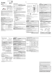
MELSEC iQ-F Series
iQ Platform-compatible PLC
The next level of industry
Designed on the concepts of outstanding performance, superior drive control and
user centric programming, Mitsubishi's MELSEC-F Series has been reborn as the
MELSEC iQ-F Series.
From stand alone use to networked system applications, MELSEC iQ-F Series brings
your business to the next level of industry.
The next level of industry
The newly reborn MELSEC iQ-F Series reaches to new areas of
application with a high-speed system bus, extensive built-in
functions and network support.
Conveyance
2
Food & Beverage
Packaging
Air-conditioning
New micro PLC designed on the concepts of ...
Outstanding Performance
Superior Drive Control
Intuitive Programming
Environment
- High-speed system bus
- Easy built-in positioning (4-axis 200 Kpps)
- Easy programming by drag and drop
- Extensive built-in functions
- Simple interpolation functions
- Reduced development time with module FB
- Enhanced security functions
- 4-axis synchronous control with Simple
Motion module (dedicated positioning
software not needed)
- Parameterized setup for
a variety of functions
- Battery-less
The next level of industry
3
Taking the iQ Platform to the
next level.
iQ platform minimizes TCO 4 by providing innovative solutions for :
Building a stable production system with enhanced productivity
Reducing the time from system development to startup for shorter product cycles
Efficiently managing and servicing the system to reduce down time and maintain
productivity
Ensuring product quality by swiftly processing enormous volumes of control data and
production data and establishing traceability
4 TCO: Total Cost of Ownership
PLC & HMI
1. MELSEC iQ-F Series greatly enhances the total system performance
with the high-speed system bus performance (150× conventional
speed 41)
2. Standardize programs with dedicated memory for function blocks
and module labels
3. Uniform and powerful security functions
Network
1. Achieve loss-less retrieval with CC-Link IE Field (future support)
1 Gbps high-speed communication (link refresh performance
40× conventional levels 41)
2. Seamless connectivity with each device using SLMP 4 (future support)
4 SLMP: SeamLess Message Protocol
Engineering Environment
1. Detect and automatically generate network configuration diagrams
from actual machines (future support)
2. Share parameters across multiple engineering software via
MELSOFT Navigator (future support)
4 1: Comparison with FX3U
4
ERP (Enterprise resource planning)
ER
P
MES (Manufacturing execution system)
ME
S
PLC & HMI
Network
Engineering
environment
n
io
at r
m e
to roll
u
A ont
C
Transparent
connectivity
d
te
a
r
eg ork
t
In etw
N
d
te g
a
r n
eg eeri
t
In in
g
En
5
Advanced Built-in Functions
Built-in Analog Input/Output
CPU Performance
(with alarm output)
A new sequence execution engine is at the core of MELSEC iQ-F,
capable of running structured programs and multiple programs,
and supports structured text and function blocks, etc.
Program capacity
64 k steps
Instruction execution
speed
(LD, MOV instruction)
34 ns
PC MIX value
14.6
instructions/μs
Fixed cycle interrupt
Program
minimum1 ms
FX5U
FX5U is equipped with 12-bit 2ch analog input and 1ch analog output.
With parameter setup, no programming is required.
Value shifting, scaling and alarm output can also be set easily with
parameters.
Ethernet
›› Example of inverter
control with analog
output
FX5U
GOT
PID control
Inverter
Built-in SD Card Slot
A built-in SD card slot is convenient for updating the program and
mass production of equipment.
Data can be logged in SD card
Office
(future support), making it easy to
analyze the system status and
production state, etc.
›› Example of mass production of
equipment using SD card
Production site
RUN/STOP/RESET Switch
The RUN/STOP switch now includes RESET function.
PLC can be rebooted without turning off the main power for
efficient debugging.
Built-in RS-485 Port (with MODBUS® function)
Connect to serial devices up to 50 m away with built-in RS-485 port.
Control for up to 16 Mitsubishi inverters is possible with dedicated
inverter communication instructions. The MODBUS function
supports a connection of up to 32 peripheral units including PLCs,
sensors and thermoregulators.
›› Inverter Communication
FX5U/FX5UC (Master)
Max. 50 m
RS-485
Max. 16 inverters
Mitsubishi inverter
6
›› MODBUS Communication
FX5U/FX5UC (Master)
Max. 50 m
MODBUS (RS-485) Max. 32 stations
MODBUS connected devices
(Inverter, Thermoregulator, etc.)
Space saving
The next level of industry
High-speed System Bus
Communication
Security
MELSEC iQ-F has advanced security functions (file password,
remote password, security key) to prevent data theft and illegal
operations by unauthorized persons.
›› Example of Security key function
Unauthorized
copy
×
×
MELSEC iQ-F realizes high-speed system bus communication at
speeds of 1.5 k words/ms (approx. 150-times faster than FX3U).
Achieve maximum performance even when using intelligent
function module with large amounts of data.
Program cannot be executed
(Program and CPU keys do not match)
SSCNET III/H
CC-Link IE Field
... Future support
High-speed System Bus Communication
(approx. 150-times faster) Comparison with FX3U
Battery-less and
Maintenance-free
Programs can be saved even without a
battery, and clock data can be saved for
ten days by supercapacitor.
(May vary by usage state)
4: Clock data and device memory can be saved (latched)
during a power outage by using the optional battery.
Built-in Ethernet Port
The Ethernet communication port can handle communication of up to
8 connections on the network, and can support multiple connections
with personal computer and other device. This port also supports
remote maintenance and other seamless SLMP communication with
host devices.
The CPU module and engineering tool (GX Works3) can
be directly connected with a single Ethernet cable.
›› Socket Communication
Directly connect to other PLCs.
›› Remote Maintenance
Program read/write can be made by
GX Works3 connected via VPN.
PC
VPN router
VPN tunnel
VPN router
›› SLMP Communication
Ethernet
Device data read-out/writing to PLC from
external device is possible.
Each device can be set easily with parameters.
HUB
PC
›› MODBUS/TCP client
7
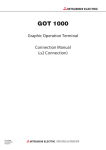
Advanced positioning function
Built-in Positioning (200 Kpps, 4-Axis built-in)
Positioning capable of 20 μs high-speed start
Up to 8 ch 200 kHz4
FX5U/FX5UC features powerful positioning functionality with 8 ch high-speed pulse
input and 4-axis pulse output.
Positioning operations including interrupt, variable speed, and simple interpolation can
easily be set up in tables and executed.
FX5U-32M : 6 ch 200 kHz+2 ch 10 kHz
FX5UC-32M : 6 ch 200 kHz+2 ch 10 kHz
1st Axis
200 Kpps
2nd Axis
200 Kpps
[Example of packing system using built-in positioning]
3rd Axis
200 Kpps
Pulse Output
4th Axis
ON (Forward Rotation)
200 Kpps
OFF (Reverse Rotation)
Rotation direction
Simple Linear Interpolation (2-Axis simultaneous start)
Y coordinate
Target position (x, y)
y
x
Start point
X coordinate
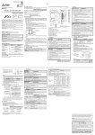
Simple Motion Module <4-Axis control module>
Positioning control with SSCNET III/H
FX5-40SSC-S is equipped with a 4-axis positioning function compatible with SSCNET III/H.
By combining linear interpolation, 2-axis circular interpolation and continuous trajectory
control in the program set with a table, a smooth trajectory can be easily drawn.
FX5-40SSC-S
3
1
2
4
1. X-axis
2. Y-axis
3. Z-axis
4. Paint
Main functions
• Linear interpolation
• Circular interpolation
• Continuous trajectory control
• S-curve acceleration/deceleration
[Example of sealing system]
8
Application examples
• Sealing system
• Automatic vending machines
• Palletizer
• Grinding system
The next level of industry
Advanced Motion Control
Making Simple Motion with compactly packed extra functions
By starting with parameter settings and the sequence program, the Simple Motion modules can realize a variety of motion control
including positioning control, advanced synchronous control, cam control and speed-torque control.
FX5U
FX5-40SSC-S
RS-485
Axis1
Inverter
MR-JE/J4 series
Axis2
Axis3
• Use synchronous control and cam control to build a system
perfect for your equipment.
• Register up to 64 types of cam patterns to respond to any type
of packaging needs.
• Perform continuous operation without stopping the workpiece
operation.
[Example of packaging machine using Simple Motion]
Synchronous control
In addition to synchronous control that replaces physical machine mechanisms such as gears, shaft, transmission and cam with software,
functions such as cam control, clutch and cam auto-generation are easily realized. Since synchronous control can be started and stopped
for each axis, programs can contain both synchronous control axes and positioning control axes.
Up to four axes can be synchronized to the synchronous encoder axis, enabling use with a variety of systems.
Cam data auto-generation
Easily program and automatically generate difficult cam data for rotary cutters just by inputting the sheet length, synchronization width,
and cam resolution, etc.
Mark detection
Cam data
Synchronous
axis length
(circumference)
Sheet
feeding
Cam
auto-generation
Synchronization
width
User-created GOT screen
Sheet length
Cam axis
(synchronized axis)
speed
Parameter settings,
including items like
sheet length, etc.
Stroke ratio
Sheet feeding
speed
Synchronization
width
Mark detection function
The cutter axis deviation can be compensated by detecting a mark on
the workpiece so the workpiece can be cut at a constant position.
[Example of rotary cutter control with mark detection and cam data]
9
User-friendly programming software
Software that comprehensively supports programming and maintenance streamlines operations.
Easily and intuitively program by making "selections" in a graphical environment.
Reduce maintenance and engineering costs with diagnosis and troubleshooting function.
System design with a convenient parts library
With GX Works3, designing a system is as easy as preparing the module configuration diagram by dragging and dropping selected parts.
Simply drag & drop
when adding a module
Drag & Drop
Auto-generation of module parameters
When preparing the module configuration diagram, simply double-click the module to automatically generate the module parameters.
A window with an easy-to-use parameter settings screen opens, enabling module parameters to be modified as needed.
Double click
Work window for related
parameters appears
Parameters automatically
added to navigation pane
10
The next level of industry
Main programming languages supported
The main IEC languages are supported by GX Works3. Various different programming languages can be used within the same project
simultaneously and can be viewed easily via the menu tab.
The labels and devices used in each program can be shared across multiple platforms, with user defined function blocks supported.
Ladder
Function block diagram
Structured text
Reduce repetitive program tasks
Global labels, local labels and module labels are supported by GX Works3. Global labels can be shared by multiple programs and with other
MELSOFT software. Local labels can be used in registered programs and function blocks. Module labels contain buffer memory information for
various intelligent function modules and eliminates the need to reference buffer memory address.
Global label editor
Drag & Drop
Drag & Drop
Local label editor
Integrated motion setup tool
GX Works3 is equipped with a special motion setup tool that makes it easy to change simple motion module settings such as
module parameters, positioning data and servo parameters. Also, the servo adjustment is simplified using it.
e
c
fi
Synchronous control parameter
Digital oscilloscope
11
Advanced MELSEC iQ-F Series
Simple and convenient parameter settings
With MELSEQ iQ-F, various device settings that
conventionally had to be programmed can be input in
table format.
Easily set the built-in functions as well as expansion
devices just by inputting values into the parameters.
The program’s execution trigger can also be set with the
parameters.
Built-in function parameters
Program parameters
CPU module
Initial execution type
(Origin point return,
initial communication),
etc.
RS-485
MODBUS
Ethernet
Scan execution type
・
・
・
・
・
[Functions set with parameters]
- Settings for CPU parameters, Ethernet port, RS485 communication port, input response time,
expansion board, memory card, security, etc.
- Settings for expansion adapters and intelligent
function module
Fixed-cycle execution type
(Sampling, positioning
communication process),
etc.
Expansion device parameters
Expansion board
Standby type
Expansion adapter
Intelligent
function module
Event execution type
(forced stop process),
etc.
・
・
・
・
・
Memory area for each application
The CPU module has 64 k steps of program memory capacity, but the MELSEC
iQ-F has a memory data area for each application, so all 64 k steps can be used
as the program area.
Comments and statements can be written freely without affecting the
program area.
Program 64 k steps
(Flash 128 kbytes)
Data (comment, etc.)
(ROM 5 Mbytes)
Device label
(RAM 120 kbytes)
Up to 4 Gbytes can be used.
[Maximum number of characters]
Comment: 1024 characters Statement: 5000 characters
Program data
Backup data
Logging data
(Future support)
(Future support)
MELSEC iQ-F Series stores the program and devices in non-volatile memory such as Flash ROM, so no
battery is required.
Flexible internal devices
A variety of devices including new latch relays and link relays, and expanded timers and counters are available.
The number of device points can be reassigned and used in the internal memory.
Providing the convenience of
special devices
In addition to the conventional special
devices, up to 12000 points of convenient
system devices compatible with
high-end devices can be added.
New high-end compatible system
devices
• SM/SD 0 to 4099
Compatible with
MELSEC iQ-R
Conventional convenient devices
• Conventional M8000 devices
gHas changed to SM8000 devices
• Conventional D8000 devices
gHas changed to SD8000 devices
(When migrating an FX3U/FX3UC program
created using GX Works2 to FX5, the devices
are automatically converted.)
12
Freely customize the latch
range setting
The latch range can be set for each device,
so the latch clear range can be selected
during the clearing operation.
Handy timer and counter settings
The timer and counter properties are
determined by data type and how
instruction is written, so programs can be
created regardless of the device number.
Timers:
OUT T0.........100 ms timer
OUTH T0 ......10 ms timer
OUTHS T0 ....1 ms timer
OUT ST0 ...... Retentive timer
Counters:
OUT C0 ........16 bit counter
OUT LC0 ...... 32 bit counter
The next level of industry
Software
Dramatically more dedicated instructions
Inverter communication command function
A great number of dedicated instructions have been added since the
FX3 Series.
The built-in Mitsubishi inverter protocol makes it possible to use
inverter communication instructions to control a Mitsubishi inverter
connected with RS-485 communication.
[FX3] 510 types increased to [FX5] 1014 types
The newly added instructions include convenient
ones that are interchangeable with the MELSEC iQ-R
and dedicated instructions for built-in functions.
(Programs created with GX Works2 can also be read in and converted.)
Intuitive and easy-to-understand arithmetic operations
Symbols can be input in the arithmetic operations making it easy
and intuitive to describe programs.
+
*
/
• IVCK :
• IVDR :
• IVRD :
• IVWR :
• IVBWR :
• IVMC :
Operation monitor
Operation control
Parameter read
Parameter write
Parameter batch write
Multiple command
(2 types of settings and 2 types of read)
4: For built-in RS-485 communication
Built-in Ethernet function
Communication is set with parameters and programs are made with
dedicated instructions.
Functions including the diagnosis function from GX Works3, SLMP
function, socket communication function and IP address change
function and unauthorized access from an external source can be
prevented with remote password.
High-performance built-in high-speed counter function
Simultaneously communicate
with up to 8 modules
Input and measure three modes by setting the parameters.
• Normal mode
• Pulse density
measurement mode
• Rotation speed
measurement mode
Up to four tables can be set for the high-speed comparison table and
up to 128 tables for the multi-point output high-speed comparison
table. The HCMOV instruction can be used to read the latest values
from the special registers.
Ethernet
MELSOFT
SLMP
Vision
system
MODBUS function
The MODBUS function can be used with parameter settings and
ADPRW (MODBUS master communication instruction [data read/
write.]) Communicate with devices up to 1200 m away using the
RS-485 communication adapter.
Reinforced built-in positioning function
Positioning is easy using table operations. Simple linear interpolation
operation is possible by using the positioning instruction DRVTBL
with multiple table operation and the multiple axis simultaneous drive
positioning instruction DRVMUL.
Max. 16 units
Max. 50 m4
RS-485
Max. 1200 m when using adapter
Master station
Slave station
Slave station
MODBUS
Diverse table operation settings for multi-speed and interrupt positioning, etc.
Standard function/function block function
110 types of basic standard function and function blocks are provided.
These can be used as parts by dragging and dropping, so when
used together with dedicated instructions, programming time can
be greatly reduced.
Drag
&
drop
13
System Configuration
FX5 Expansion Adapters
FX5U CPU Module
FX5 Expansion Modules
Max. 6
Expansion Adapters
Flagship model equipped with advanced built-in functions
and diverse expandability
FX5 Expansion Board
Simplifying use with renewed expansion modules!
FX5U is equipped with analog functions, communication and high-speed
Max. 164
Expansion Modules
I/O, and can easily be expanded with expansion boards and adapters.
The high-speed system bus communication brings out the maximum
performance of expansion devices equipped with intelligent functions.
4: Excluding extension power supply module
FX5 Expansion Adapters
FX5U CPU Modules
Max.
2 ch
Communication
FX5-232ADP For RS-232C communication
FX5-485ADP For RS-485 communication
FX5 Expansion Boards
FX5U-32MR/ES
FX5U-32MT/ES
Max.
FX5U-32MT/ESS
AC
AC
AC
D
D
D
R
T1
T2
FX5U-64MR/ES
FX5U-64MT/ES
FX5U-64MT/ESS
AC
AC
AC
D
D
D
R
T1
T2
FX5U-80MR/ES
FX5U-80MT/ES
FX5U-80MT/ESS
AC
AC
AC
D
D
D
R
T1
T2
1 ch
Max.
4 ch
Analog
Communication
FX5-4AD-ADP For input
FX5-4DA-ADP For output
FX5-232-BD
FX5-485-BD
FX5-422-BD-GOT
For RS-232C communication
For RS-485 communication
For RS-422 GOT communication
AC AC power supply
R Relay output
T1 Transistor output (sink)
Option
Battery
FX3U-32BL
14
SD card
NZ1MEM-2GBSD (2 GB)
NZ1MEM-4GBSD (4 GB)
Programming software
GX Works3
D
DC input (sink/source)
T2 Transistor output (source)
The next level of industry
Generic Specifications
Item
Power supply, input/output
Generic Specifications
Power supply specifications
100 to 240 V AC 50/60 Hz
Power consumption
30 W (32M), 40 W (64M), 45 W (80M)
Rush current
FX5U-32M[]: max. 25 A 5 ms or less/100 V AC, max. 50 A 5 ms or less/200 V AC
FX5U-64M[]/FX5U-80M[]: max. 30 A 5 ms or less/100 V AC, max. 60 A 5 ms or less/200 V AC
5 V DC power supply capacity
900 mA or less (32M), 1100 mA or less (64M, 80M)
24 V DC power supply capacity
400 mA or less (32M), 600 mA or less (64M, 80M)
When using external power supply for CPU module input: 480 mA or less (32M) , 740 mA or less (64M) , 770 mA or less (80M)
Input specifications
24 V DC, 5.3 mA (X020 and above: 4 mA)
Output specifications
Relay output type: 2 A/1 point, 8 A/4 points common, 8 A/8 points common 250 V AC (240 V for CE, UL/cUL Standard compliance), 30 V DC or less
Transistor output type: 0.5 A/1 point, 0.8 A/4 points, 1.6 A/8 points common 5 to 30 V DC
Input/output expansion
Expansion device for FX5 can be connected
Built-in communication port
Ethernet (100BASE-TX/10BASE-T),
RS-485 (MELSOFT connection, MC protocol, non-protocol communication, MODBUS RTU, inverter communication, N:N communication)
Built-in memory card slot
1 slot for SD memory card
Built-in analog input/output
Input 2 ch, output 1 ch
FX5 Expansion Modules
I/O Modules
Powered I/O Modules
Extension Power Supply Module
Intelligent Function Modules
Unpowered I/O Modules
Simple Motion
FX5-40SSC-S
Powered I/O Modules
FX5-32ER/ES
FX5-32ET/ES
Input
FX5-8EX/ES
FX5-16EX/ES
FX5-1PSU-5V
Network
CC-Link/IE Field slave
FX5-8EYT/ESS
FX5-16EYR/ES
FX5-16EYT/ES
FX5-16EYT/ESS
FX5-32ET/ESS
Bus Conversion Module
Extension Power Supply Module
Output
FX5-8EYR/ES
FX5-8EYT/ES
... Future support
FX3 Expansion Modules
Extension Power Supply Module
Intelligent Function Modules
Analog
FX3U-4AD
FX3U-4DA
For input
For output
Positioning
FX3U-1PG
For high-speed output
FX3U-64CCL
FX3U-16CCL-M
CC-Link slave
CC-Link master
Temperature control
FX3U-4LC
Temperature control
High Speed counter
FX3U-2HC
For high-speed input
Network
Bus Conversion Module
FX5-CNV-BUS
Extension Power Supply Module
FX3U-1PSU-5V
The parameters for FX3U intelligent function module must be set by PLC program.
When connecting FX3 expansion module, FX3 speed is applied as the bus speed for accessing
the FX3 expansion module.
15
FX5 Expansion Adapters
FX5UC CPU Module
FX5 Expansion Modules
(connector type)
Connector Conversion Module
FX5 Expansion Modules
(terminal block type)
Max. 6
Expansion Adapters
Compact body packed with diverse functions.
Compact expansion module contributes to system downsizing!
Max. 164
Expansion Modules
The expansion module compatible with FX5UC is compact and easy-to-use,
and helps to downsize your system.
Easily connect to the FX5 and FX3 expansion modules with the variety of
4: Due to power limitations, only 12 modules can be directly connected to the CPU module.
Up to 16 modules can be connected using the power supply module (future support).
Excluding connector conversion module
conversion modules available.
FX5 Expansion Adapters
FX5UC CPU Modules
FX5 Expansion Modules (connector type)
I/O Modules
Sink type
Sink type
Max.
2 ch
Communication
FX5-232ADP For RS-232C communication
FX5-485ADP For RS-485 communication
DC D1 T1
FX5UC-32MT/D
FX5-C32EX/D
FX5-C32EYT/D
For input expansion
For output expansion
FX5-C32ET/D
For I/O expansion
Source type
Source type
Max.
4 ch
Analog
FX5-4AD-ADP For input
FX5-4DA-ADP For output
FX5UC-32MT/DSS
DC DC power supply
D1 DC input (sink)
T1 Transistor output (sink)
DC D2 T2
D2 DC input (sink/source)
T2 Transistor output (source)
Option
Battery
FX3U-32BL
SD card
NZ1MEM-2GBSD (2 GB)
NZ1MEM-4GBSD (4 GB)
Terminal block for sink type I/O
FX-16E-TB
FX-16EYT-TB
FX-16EYR-TB
FX-16EX-A1-TB
FX-16EYS-TB
FX-32E-TB
Terminal block for source type I/O
FX-16E-TB/UL
FX-16EYT-ES-TB/UL
FX-16EYR-ES-TB/UL
FX-16EYT-ESS-TB/UL
FX-16EYS-ES-TB/UL
FX-32E-TB/UL
Programming software
GX Works3
I/O cable
l General-purpose I/O cable
FX-16E-500CAB-S (5 m, 20-pin)
l For terminal block
FX-16E-[]CAB (double-end 20-pin)
[]: 150 (1.5 m)/300 (3 m)/500 (5 m)
16
l For terminal block
FX-16E-[]CAB-R (20-pin)
[]: 150 (1.5 m)/300 (3 m)/500 (5 m)
FX5-C32EX/DS
For input expansion
FX5-C32EYT/DSS For output expansion
FX5-C32ET/DSS For I/O expansion
The next level of industry
Generic Specifications
Item
Power supply, Input/output
Generic specifications
Power supply specifications
24 V DC
Power consumption
8 W (32M)
Rush current
Max. 30 A 0.5 ms or less/24 V DC
5 V DC power supply capacity
720 mA or less (32M)
24 V DC power supply capacity
500 mA or less (32M)
Input specifications
24 V DC, 5.3 mA
Output specifications
Transistor output type: Y000 to Y003 0.3 A/1 point, Y004 and higher 0.1 A/1 point, 0.8 A/8 points common 5 to 30 V DC
Input/output expansion
Expansion device for FX5UC and FX5 (connector adapter required) can be connected
Built-in communication port
Ethernet (100BASE-TX/10BASE-T),
RS-485 (MELSOFT connection, MC protocol, non-protocol communication, MODBUS RTU, inverter communication, N:N communication)
Built-in memory card slot
1 slot for SD memory card
FX5 Expansion Modules (terminal block type)
Connector Conversion Module
I/O Modules
Output Modules
Intelligent Function Modules
Sink type
Simple Motion
FX5-40SSC-S
Output
FX5-8EYT/ES
FX5-16EYT/ES
Source type
Input
Connector Conversion Module
FX5-8EX/ES
FX5-16EX/ES
FX5-CNV-IFC
Network
Output
CC-Link/IE Field slave
FX5-8EYR/ES
FX5-16EYR/ES
... Future support
Output
FX5-8EYT/ESS
FX5-16EYT/ESS
Bus Conversion Modules
FX3 Expansion Modules
Intelligent Function Modules
Analog
Bus Conversion Module
FX5-CNV-BUS
FX3U-4AD
FX3U-4DA
For input
For output
Temperature control
FX3U-4LC
Temperature control
High Speed counter
Positioning
FX3U-1PG
For high-speed output
FX3U-64CCL
FX3U-16CCL-M
CC-Link slave
CC-Link master
FX3U-2HC
For high-speed input
Network
Bus Conversion Module
FX5-CNV-BUSC
The parameters for FX3U intelligent function module must be set by PLC program.
When connecting FX3 expansion module, FX3 speed is applied as the bus speed for accessing the FX3 expansion module.
17
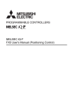
Selecting the FX5U Model
Product configuration
8
Control scale: 32 to 256 points
(CPU module: 32/64/80 points)
l Control points up to 512 input/output points,
including remote input/output4
1
2
4
3
5
6
9
10
l
7
4 : CC-Link
Type
Details
Connection details, model selection
PLC with built-in CPU, power supply,
input/output and program memory.
CPU module
I/O module
Various expansion devices can be connected.
Product for expanding I/O. Some products are powered.
FX5 extension power supply module
Module for expanding power supply if CPU module’s internal
power supply is insufficient. Extension cable is enclosed.
FX5 intelligent function module
Module with functions other than input/output.
Bus conversion module
FX5 expansion board
FX5 expansion adapter
FX3 extension power supply module
FX3 intelligent function module
Conversion module for connecting FX3 Series expansion
module.
Board connected to front of CPU module to expand
functions.
Adapter connected to left side of CPU module to expand
functions.
Module for expanding power supply if CPU module’s internal
power supply is insufficient.
Input/output can be expanded to up to 256 points.
(Expansion module: Max. 16 modules (excluding extension power supply module)).
The total with CC-Link remote input/output is max. 512 points.
Power can be supplied to I/O module, intelligent function module, and bus conversion
module.
Up to 2 modules can be connected.
Up to 16 expansion modules including the I/O module can be connected (excluding the
extension power supply module).
FX3 Series expansion module can be connected only to the right side of the bus
conversion module.
Up to 1 module can be connected to the front of the CPU module.
(Expansion adapter can also be used.)
Up to 6 modules can be connected to the left side of the CPU module.
The bus conversion module is required for use. Up to 2 modules can be connected.
The bus conversion module is required for use. When using the FX3 extension power
supply module, up to 8 modules 4 can be used. When not using the FX3 extension power
supply unit, up to 6 modules 4 can be used.
Module with functions other than input/output.
4 : Excluding some models
CPU module
Type
FX5U-32MR/ES
FX5U-32MT/ES
FX5U-32MT/ESS
FX5U-64MR/ES
FX5U-64MT/ES
FX5U-64MT/ESS
FX5U-80MR/ES
FX5U-80MT/ES
FX5U-80MT/ESS
Function
CPU module
(service power built-in)
Number of
occupied input/
output points
Power supply capacity
5 V DC power
24 V DC service
supply
power supply
32 points
900 mA
400 mA
(480 mA 4)
64 points
1100 mA
600 mA
(740 mA 4)
80 points
1100 mA
600 mA
(770 mA 4)
I/O type
No. of input
points
DC input (sink/source)/relay output
DC input (sink/source)/transistor (sink)
16 points
DC input (sink/source)/transistor (source)
DC input (sink/source)/relay output
DC input (sink/source)/transistor (sink)
32 points
DC input (sink/source)/transistor (source)
DC input (sink/source)/relay output
DC input (sink/source)/transistor (sink)
40 points
DC input (sink/source)/transistor (source)
No. of output
points
16 points
32 points
40 points
4 : Power supply capacity when using external power supply for input circuit.
I/O module
Type
FX5-32ER/ES
FX5-32ET/ES
FX5-32ET/ESS
Function
Input/output module
(service power built-in)
Number of
occupied input/
output points
32 points
Power supply capacity
5 V DC power
24 V DC service
supply
power supply
965 mA
250 mA
(310 mA 4)
4 : Power supply capacity when using external power supply for input circuit.
FX5 extension power supply module
Type
FX5-1PSU-5V
Function
Extension power supply
Number of
occupied input/
output points
―
4 : Refer to the manual if the ambient temperature exceeds 40°C.
18
Power supply capacity
5 V DC power
24 V DC power
supply
supply
4
1200 mA
300 mA 4
I/O type
No. of input
points
DC input(sink/source)/relay output
DC input (sink/source)/transistor (sink)
16 points
DC input (sink/source)/transistor (source)
No. of output
points
16 points
The next level of industry
I/O module
Type
FX5-8EX/ES
Current consumption
Number of occupied
input/output points
I/O format
5 V DC internal current consumption
24 V DC internal current consumption
DC input (sink/source)
8 points
75 mA
50 mA
16 points
100 mA
85 mA
8 points
75 mA
75 mA
16 points
100 mA
125 mA
5 V DC internal current consumption
24 V DC internal current consumption
―
―
5 V DC internal current consumption
24 V DC internal current consumption
150 mA
―
5 V DC internal current consumption
24 V DC internal current consumption
FX5-16EX/ES
DC input (sink/source)
FX5-8EYR/ES
Relay output
FX5-8EYT/ES
Transistor output (sink)
FX5-8EYT/ESS
Transistor output (source)
FX5-16EYR/ES
Relay output
FX5-16EYT/ES
Transistor output (sink)
FX5-16EYT/ESS
Transistor output (source)
24 V DC external electric supply
―
FX5 intelligent function module
Type
FX5-40SSC-S
Current consumption
Number of occupied
input/output points
Function
Simple Motion 4-axis control
(SSCNET III/H compatible)
8 points
24 V DC external electric supply
250 mA
Bus conversion module
Type
FX5-CNV-BUS
Current consumption
Number of occupied
input/output points
Function
Bus conversion FX5→FX3
8 points
24 V DC external electric supply
―
FX5 Expansion board
Type
FX5-232-BD
RS-232C communication
FX5-485-BD
RS-485 communication
FX5-422-BD-GOT
RS-422 communication
(for GOT connection)
Current consumption
Number of occupied
input/output points
Function
24 V DC external electric supply
20 mA
―
―
―
20 mA 4
4 : The current consumption will increase when the 5 V type GOT is connected.
FX5 Expansion adapter
Type
FX5-232ADP
RS-232C communication
Current consumption
Number of occupied
input/output points
Function
5 V DC internal current consumption
30 mA
FX5-485ADP
RS-485 communication
FX5-4AD-ADP
4 ch voltage input/current input
FX5-4DA-ADP
4 ch voltage output/current output
24 V DC external electric supply
30 mA
20 mA
―
24 V DC internal current consumption
―
20 mA
10 mA
―
160 mA
FX3 extension power supply module
Type
FX3U-1PSU-5V
Current consumption
Number of occupied
input/output points
Function
Extension power supply
―
5 V DC internal current consumption
24 V DC internal current consumption
1000 mA 4
300 mA 4
5 V DC internal current consumption
24 V DC internal current consumption
24 V DC external electric supply
―
4 : Refer to the manual if the ambient temperature exceeds 40°C.
FX3 intelligent function module
Type
FX3U-4AD
Current consumption
Number of occupied
input/output points
Function
4 ch voltage input/current input
FX3U-4DA
4 ch voltage output/current output
FX3U-4LC
4-loop temperature control
(thermocouple, PT and mini voltage)
FX3U-16CCL-M
CC-Link Master
(Ver. 2.00 and Ver. 1.10 compatible)
FX3U-64CCL
CC-Link intelligent device station
FX3U-1PG
Pulse output for independent 1-axis control
FX3U-2HC
2 ch high-speed counter
8 points
24 V DC external electric supply
110 mA
90 mA
120 mA
160 mA
160 mA
50 mA
―
4
240 mA
―
220 mA
8 points
150 mA
40 mA
245 mA
―
4 : Varies according to settings.
Calculation of current consumed
by expansion modules
The power required for the expansion adapter,
expansion board and expansion module is supplied from
the CPU module or extension power supply module.
Use the following calculations to confirm whether the
required power can be supplied. (All calculations must
be satisfied.)
CPU module
Expansion
adapter
)
Calculation
results
0 mA
Total current consumption
total of connected
expansion devices
Calculation
results
0 mA4
(
Powered
I/O module
Input
module
Output
module
Intelligent Intelligent Intelligent Extension power
module module
module supply module
Power fed from powered I/O module
5 V DC power supply
capacity
(powered I/O module)
Total current consumption
total of connected
expansion devices
)
Calculation
results
0 mA
Total current consumption
total of connected
expansion devices
Calculation
results
0 mA4
(
)
24 V DC service power supply
capacity
(powered I/O module)
(
Input
module
Output
module
Bus
Intelligent conversion Intelligent
module
module
module
Power fed from extension power supply module
(Only 5 V DC power for input module)
■Power fed from extension power supply module
calculations are required when using the FX3 Series
[5 V DC power supply] (Separate
extension power supply module)
[24 V DC power supply]
[24 V DC power supply]
24 V DC service power supply
capacity
(CPU module)
Output
module
■Power fed from powered I/O module
[5 V DC power supply]
Total current consumption
total of connected
expansion devices
(
Input
module
Power fed from CPU module
■Power fed from CPU module
[5 V DC power supply]
5 V DC power supply
capacity
(CPU module)
Expansion
board
5 V DC power supply
capacity
(Extension power supply module)
Total current consumption
total of connected
expansion devices
)
Calculation
results
0 mA
Total current consumption
total of connected
expansion devices
Calculation
results
0 mA4
(
[24 V DC power supply]
)
24 V DC service power supply
capacity
(Extension power supply module)
(
)
<Caution> If the calculation results are negative, the power capacity is exceeded so review the system configuration.
4: The 24 V DC service power calculation results value (when positive) indicate the 24 V DC service power supply's remaining capacity,
and can be used as an external load power.
The number of connected modules may be limited for some products. Refer to page 20 for details.
19
Rules of System Configuration
The FX5U CPU module can control a total of 512 points including the CPU module and expansion device input/output points and remote input/output points.
Number of input/output points on whole system
Up to 512 points
1. Number of input/output points (including occupied input/output points)
Up to 256 points
Up to 16 modules
FX3
FX5
Expansion
adapters
(analog)
Expansion
adapters
CPU module
Expansion
board
(communication)
Up to 4 modules Up to 2 modules
Intelligent
module
I/O module
Extension
power supply
module
I/O module
Extension
Bus conversion power supply
module
module
Intelligent
module
Up to 1 module
Up to 8 modules
Up to 1 module
Intelligent
module
Up to 8 modules
Up to 8 modules
Up to 12 modules
Up to 10 modules
2. Number of remote input/output points for CC-Link
Intelligent
module
Total up to 2 modules
Up to 384 points
CC-Link
Remote I/O station
Remote I/O station
Remote I/O station
Remote I/O station
Number of I/O points
The maximum number of input/output points that can be configured with the FX5U is shown below.
Maximum number of
input/output points
Number of occupied input/output points
CPU module
256 points
≧
(A) points
I/O module
+
Intelligent module
Total (B) points
+
(C) modules
× 8 points
Expansion adapter, expansion board and extension power supply module do not occupy any
input/output.
(A): Number of CPU module input/output points (B): Total number of I/O module input/output points (C): Total number of intelligent modules
Total
512 points
or less
Number of input/output points when using network master module
The maximum number of input/output points when using the network master module is shown below.
Maximum number of
input/output points
Number of occupied remote input/output points
CC-Link
384 points
≧
(D) station
× 32 points
CC-Link is the total of the number of remote I/O stations x 32 points.
(Calculated as 32 points regardless of the number of remote I/O points.)
(D): Number of CC-Link remote I/O stations
Limitation on number of modules when expanding
The number of connectable modules is limited for the following products. Refer to the manual for details.
Type
Intelligent function module for FX3 Series
Model/type
FX3U-4AD
FX3U-4DA
FX3U-1PG
FX3U-4LC
FX3U-16CCL-M
FX3U-64CCL
FX3U-2HC
Setting method/precautions
When using FX3U extension power supply module: Up to 8 modules can be connected per system
When not using FX3U extension power supply module: Up to 6 modules can be connected per system.
Up to 1 module can be connected for the entire system.
Up to 2 modules can be connected for the entire system.
When not using the FX3U-1PSU-5V, connect immediately after the bus conversion module.
Refer to the manual for details on each device.
20
The next level of industry
Selecting the FX5UC Model
Product configuration
1
7
2
3
4
5
6
8
Control scale: 32 to 256 points
(CPU module: 32 points)
l Control points up to 512 input/output points,
including remote input/output4
l
4 : CC-Link
Type
Details
Connection details, model selection
PLC with built-in CPU, power supply, input/output and
program memory.
Various expansion devices can be connected.
I/O module (connector type)
Connector type product for expanding the input/output.
The input/output can be expanded to up to 256 points.
(Expansion module: Max. 12 modules (excluding connector conversion module)).
The total with CC-Link remote input/output is max. 512 points.
Connector conversion module
Converts the connector for connecting the FX5 Series
expansion devices.
Expansion devices for the FX5 Series can be connected.
I/O module (terminal block type)
Product for expanding the input/output.
FX5 intelligent function module
Module with functions other than input/output.
CPU module
The input/output can be expanded to up to 256 points.
(Expansion module: Max. 12 modules (excluding connector conversion module)).
The total with CC-Link remote input/output is max. 512 points.
Up to 12 expansion modules including the I/O module can be connected (excluding the
connector conversion module).
The FX3 Series expansion module can be connected only to the right side of the bus
conversion module.
Conversion module for connecting FX3 Series expansion
module.
Adapter connected to left side of CPU module to expand
functions.
Bus conversion module
FX5 expansion adapter
FX3 intelligent function module
Up to 6 modules can be connected to the left side of the CPU module.
A bus conversion module is required for use.
Up to 6 bus conversion modules 4 can be connected on the right side.
Module with functions other than input/output.
4 : Excluding some models
CPU module
Type
FX5UC-32MT/D
FX5UC-32MT/DSS
Power supply capacity
5 V DC power
24 V DC service
supply
power supply
Number of
occupied input/
output points
Function
CPU module
32 points
720 mA
I/O type
No. of input
points
DC input (sink)/transistor (sink)
16 points
DC input (sink/source)/transistor (source)
500 mA
No. of output
points
16 points
I/O module(connector type)
Type
FX5-C32EX/D
FX5-C32EX/DS
FX5-C32EYT/D
FX5-C32EYT/DSS
FX5-C32ET/D
FX5-C32ET/DSS
I/O format
Current consumption
Number of occupied input/
output points
DC input (sink)
DC input (sink/source)
Transistor output (sink)
32 points
Transistor output (source)
DC input (sink)/Transistor output (sink)
DC input (sink/source)/Transistor output (source)
5 V DC internal current
consumption
24 V DC internal current
consumption
24 V DC external electric
supply
―
120 mA
200 mA
―
100 mA
Connector conversion module
Type
FX5-CNV-IFC
Function
Connector conversion
Current consumption
Number of occupied input/
output points
―
5 V DC internal current
consumption
―
24 V DC internal current
consumption
―
24 V DC external electric
supply
―
21
I/O module (terminal block type)
Type
FX5-8EX/ES
Current consumption
Number of occupied input/
output points
Function
5 V DC internal current
consumption
24 V DC internal current
consumption
DC input (sink/source)
8 points
75 mA
50 mA 4
16 points
100 mA
85 mA 4
8 points
75 mA
75 mA
16 points
100 mA
125 mA
FX5-16EX/ES
DC input (sink/source)
FX5-8EYR/ES
Relay output
FX5-8EYT/ES
Transistor output (sink)
FX5-8EYT/ESS
Transistor output (source)
FX5-16EYR/ES
Relay output
FX5-16EYT/ES
Transistor output (sink)
FX5-16EYT/ESS
Transistor output (source)
24 V DC external electric supply
―
4 : Since external power supply is used for input circuit in FX5UC CPU module systems, power supply from CPU module is not included.
FX5 intelligent function module
Type
FX5-40SSC-S
Current consumption
Number of occupied input/
output points
Function
Simple Motion 4-axis control
(SSCNET III/H compatible)
8 points
5 V DC internal current
consumption
―
24 V DC internal current
consumption
―
24 V DC external electric supply
250 mA
Bus conversion module
Type
Current consumption
Number of occupied input/
output points
Function
FX5-CNV-BUSC
Bus conversion (connector)FX5→FX3
FX5-CNV-BUS
Bus conversion FX5→FX3
8 points
5 V DC internal current
consumption
150 mA
24 V DC internal current
consumption
―
24 V DC external electric supply
―
FX5 Expansion adapter
Type
Current consumption
Number of occupied input/
output points
Function
5 V DC internal current
consumption
30 mA
FX5-232ADP
RS-232C communication
FX5-485ADP
RS-485 communication
FX5-4AD-ADP
4 ch voltage input/current input
FX5-4DA-ADP
4 ch voltage output/current output
30 mA
20 mA
―
24 V DC internal current
consumption
24 V DC external electric supply
―
20 mA
10 mA
―
160 mA
FX3 intelligent function module
Type
Current consumption
Number of occupied input/
output points
Function
FX3U-4AD
4 ch voltage input/current input
FX3U-4DA
4 ch voltage output/current output
FX3U-4LC
4-loop temperature control
(thermocouple, PT and mini voltage)
FX3U-16CCL-M
CC-Link Master
(Ver. 2.00 and Ver. 1.10 compatible)
FX3U-64CCL
CC-Link intelligent device station
FX3U-1PG
Pulse output for independent 1-axis control
FX3U-2HC
2 ch high-speed counter
8 points
5 V DC internal current
consumption
24 V DC internal current
consumption
90 mA
120 mA
160 mA
160 mA
50 mA
―
4
24 V DC external electric supply
110 mA
240 mA
―
220 mA
8 points
150 mA
40 mA
245 mA
―
4 : Varies according to settings.
Calculation of current consumed by expansion modules
The power required for the expansion adapter and expansion module is supplied from the CPU module.
Use the following calculations to confirm whether the required power can be supplied.
(All calculations must be satisfied.)
Total current consumption
total of connected
expansion devices
)
Calculation
results
0 mA
Total current consumption
total of connected
expansion devices
Calculation
results
0 mA
(
22
(
Input
module
Output
module
Bus
Connector Intelligent
Intelligent
conversion module conversion module
module
module
<Caution> If the calculation results are negative, the power capacity is exceeded so review
the system configuration.
[24 V DC power supply]
24 V DC service power supply
capacity
(CPU module)
CPU module
Power fed from CPU module
■Power fed from CPU module
[5 V DC power supply]
5 V DC power supply
capacity
(CPU module)
Expansion
adapter
)
The number of connected modules may be limited for some products. Refer to page 20 for details.
The next level of industry
Rules of System Configuration
The FX5UC CPU module can control a total of 512 points including the CPU module and expansion device input/output points and remote input/output points.
Number of input/output points on whole system
Up to 512 points
1. Number of input/output points (including occupied input/output points)
Up to 256 points
Up to 12 modules
FX3
FX5
Expansion
adapters
(analog)
Expansion
adapters
(communication)
CPU module
I/O module
Connector
conversion
Module
I/O module
Up to 1 module
Up to 1 module
Up to 4 modules Up to 2 modules
Intelligent
module
Up to 6 modules
Up to 8 modules
Total up to 12 modules
2. Number of remote input/output points for CC-Link
Intelligent
module
Bus conversion
module
Intelligent
module
Up to 384 points
CC-Link
Remote I/O station
Remote I/O station
Remote I/O station
Remote I/O station
Number of I/O points
The maximum number of input/output points that can be configured with the FX5UC is shown below.
Maximum number of
input/output points
Number of occupied input/output points
CPU module
256 points
≧
(A) points
I/O module
+
Intelligent module
Total (B) points
+
(C) modules
× 8 points
The expansion adapter and connector conversion module are not included in the number of
occupied points.
(A): Number of CPU module input/output points (B): Total number of I/O module input/output points (C): Total number of intelligent modules
Total
512 points
or less
Number of input/output points when using network master module
The maximum number of input/output points when using the network master module is shown below.
Maximum number of
input/output points
Number of occupied remote input/output points
CC-Link
384 points
≧
(D) station
× 32 points
CC-Link is the total of the number of remote I/O stations x 32 points.
(Calculated as 32 points regardless of the number of remote I/O points.)
(D): Number of CC-Link remote I/O stations
Limitation on number of modules when expanding
The number of connectable modules is limited for the following products. Refer to the manual for details.
Type
Intelligent function module for FX3 Series
Model/type
FX3U-4AD
FX3U-4DA
FX3U-1PG
FX3U-4LC
FX3U-16CCL-M
FX3U-64CCL
FX3U-2HC
Setting method/precautions
Up to 6 modules can be connected for the entire system.
Up to 1 module can be connected for the entire system.
Up to 2 modules can be connected for the entire system.
Connect immediately after the bus conversion module.
Refer to the manual for details on each device.
23
Product specifications
CPU module specification
Generic Specifications
Specifications
Item
FX5U
Operating ambient temperature
41
0 to 55°C (32 to 131°F)
Storage ambient temperature
-25 to 75°C (-13 to 167°F)
Operating ambient humidity
5 to 95%RH, non-condensation
Storage ambient humidity
5 to 95%RH, non-condensation
Vibration resistance 4344
Installed on
DIN rail
Direct
installing
FX5UC
42
Frequency
Acceleration
Half amplitude
5 to 8.4 Hz
―
1.75 mm
8.4 to 150 Hz
4.9 m/s2
―
5 to 8.4 Hz
―
3.5 mm
8.4 to 150 Hz
9.8 m/s
2
Sweep count
10 times each in X, Y, Z directions
(80 min in each direction)
―
Frequency
Acceleration
Half amplitude
Sweep count
5 to 8.4 Hz
―
1.75 mm
8.4 to 150 Hz
4.9 m/s2
―
10 times each in X, Y, Z directions
(80 min in each direction)
―
147 m/s2, Action time: 11 ms, 3 times by half-sine pulse in each direction X, Y, and Z
Shock resistance 43
Grounding
Class D grounding (grounding resistance: 100 Ω or less) <Common grounding with a heavy electrical system is not allowed.> 45
Working atmosphere
Free from corrosive or flammable gas and excessive conductive dust
Operating altitude 46
0 to 2000 m
Installation location
Inside a control panel
Overvoltage category47
II or less
Pollution degree 48
2 or less
Equipment class
Class 2
4 1 : The simultaneous ON ratio of available PLC inputs or outputs changes with respect to the ambient temperature, refer to
manuals of each product.
4 2 : For details on Intelligent function modules, refer to manuals of each product.
4 3 : The criterion is shown in IEC61131-2.
4 4 : When the system has equipment which specification values are lower than above mentioned vibration resistance specification
values, the vibration resistance specification of the whole system is corresponding to the lower specification.
4 5 : For grounding, refer to manuals of each product.
4 6 : The PLC cannot be used at a pressure higher than the atmospheric pressure to avoid damage.
4 7 : This indicates the section of the power supply to which the equipment is assumed to be connected between the public electrical power
distribution network and the machinery within premises. Category II applies to equipment for which electrical power is supplied from
fixed facilities. The surge voltage withstand level for up to the rated voltage of 300 V is 2500 V.
4 8 : This index indicates the degree to which conductive material is generated in the environment in which the equipment is used. Pollution
level 2 is when only non-conductive pollution occurs. Temporary conductivity caused by condensation must be expected occasionally.
Power Supply Specifications
Specifications
Item
FX5U-32M[]
Rated voltage
FX5U-64M[]
FX5U-80M[]
100 to 240 V AC
FX5UC-32MT/[]
24 V DC
Allowable supply voltage range
85 to 264 V AC
20.4 to 28.8 V DC
Frequency rating
50/60 Hz
―
Allowable instantaneous power failure time
Operation can be continued upon occurrence of instantaneous power failure for 10 ms or less.
Operation can be continued upon
occurrence of instantaneous power
failure for 5 ms or less.
125 V, 3.15 A Time-lag fuse
Power fuse
250 V, 3.15 A Time-lag fuse
250 V, 5 A Time-lag fuse
Rush current
25 A max. 5 ms or less/100 V AC
50 A max. 5 ms or less/200 V AC
30 A max. 5 ms or less/100 V AC
60 A max. 5 ms or less/200 V AC
Power consumption 41
30 W
40 W
45 W
8W
5 V DC power supply capacity43
900 mA
1100 mA
1100 mA
720 mA
Supply capacity when service
power supply is used for input
circuit of the CPU module
400 mA
600 mA
600 mA
Supply capacity when external
power supply is used for input
circuit of the CPU module
480 mA
740 mA
770 mA
24 V DC power
supply capacity4243
30 A max. 0.5 ms or less/24 V DC
500 mA
4 1 : This item shows value when all 24 V DC service power supplies are used in the maximum configuration connectable to the CPU module. (The current of the input circuit is included.)
4 2 : When I/O modules are connected, they consume current from the 24 V DC service power. For details on the service power supply, refer to manuals of each product.
4 3 : Internal power supply in case of FX3UC-32MT/[]
Performance Specifications
Specifications
Item
Control system
Input/output control system
Programming specifications
Operation specifications
Command processing time
Memory capacity
Refresh system (Direct access input/output allowed by specification of direct access input/output [DX, DY])
Programming language
Ladder diagram (LD), structured text (ST), function block diagram/ladder diagram (FBD/LD)
Programming extension function
Function block (FB), structured ladder, label programming (local/global)
Constant scan
0.2 to 2000 ms (can be set in 0.1 ms increments)
Fixed cycle interrupt
1 to 60000 ms (can be set in 1 ms increments)
Timer performance specifications
100 ms, 10 ms, 1 ms
No. of program executions
32
No. of FB files
16 (Up to 15 for user)
Execution type
Standby type, initial execution type, scan execution type, event execution type
Interrupt type
Internal timer interrupt, input interruption, high-speed comparison match interrupt
LD X0
34 ns
MOV D0 D1
34 ns
Program capacity
64 k steps (128 kbytes, flash memory)
SD memory card
Memory card capacity (SD/SDHC memory card: Max. 4 GB)
Device/label memory
120 kbytes
Data memory/standard ROM
Flash memory (Flash ROM) write count
File storage capacity
No. of input/output points
Power failure retention 42
5 Mbytes
Max. 20000 times
Device/label memory
1
Data memory
P: No. of program files/FB: No. of FB files
P: 32, FB: 16
SD memory card
Clock function
FX5U/FX5UC
Stored-program repetitive operation
2 GB: 51141
4 GB: 65534 41
Display data
Year, month, day, hour, minute, second, day of week (leap year automatic detection)
Precision
-2.96 to +3.74 (TYP.+1.42) s/d (Ambient temperature: 0°C (32°F))
-3.18 to +3.74 (TYP.+1.50) s/d (Ambient temperature: 25°C (77°F))
-13.20 to +2.12 (TYP.-3.54) s/d (Ambient temperature: 55°C (131°F))
(1) No. of input/output points
256 points or less
(2) No. of remote I/O points
384 points or less
Total No. of points of (1) and (2)
512 points or less
Retention method
Large-capacity capacitor
Retention time
10 days (Ambient temperature: 25°C (77°F))
Data retained
Clock data
4 1 : The value listed above indicates the number of files stored in the root folder.
4 2 : Clock data is retained using the power accumulated in a large-capacity capacitor incorporated into the PLC. When voltage of the large-capacity capacitor drops, clock data is no longer accurately retained. The retention period of a fully charged
capacitor (electricity is conducted across the PLC for at least 30 minutes) is 10 days (ambient temperature: 25°C (77°F)). How long the capacitor can hold the data depends on the operating ambient temperature. When the operating ambient
temperature is high, the holding period is short.
24
The next level of industry
Refer to the manual for details on each device.
Number of device points
Item
Base
Input relay (X)
No. of user device points
8
1024 points
10
32768 points (can be changed with parameter) 41
Latch relay (L)
10
32768 points (can be changed with parameter) 41
Link relay (B)
16
32768 points (can be changed with parameter) 41
Annunciator (F)
10
32768 points (can be changed with parameter) 41
Link special relay (SB)
16
32768 points (can be changed with parameter) 41
Step relay (S)
10
4096 points (fixed)
10
1024 points (can be changed with parameter) 41
Timer (T)
Counter system
No. of index register points
The total number of X and Y assigned to input/output points is up to 256 points.
Output relay (Y)
Accumulation timer system
Module access device
1024 points
Internal relay (M)
Timer system
No. of system device points
Max. number of points
8
Accumulation timer (ST)
10
1024 points (can be changed with parameter) 41
Counter (C)
10
1024 points (can be changed with parameter) 41
Long counter (LC)
10
1024 points (can be changed with parameter) 41
Data register (D)
10
8000 points (can be changed with parameter) 41
Link register (W)
16
32768 points (can be changed with parameter) 41
Link special register (SW)
16
32768 points (can be changed with parameter) 41
Special relay (SM)
10
10000 points (fixed)
12000 points (fixed)
Special register (SD)
10
Intelligent function module device
10
65536 points (designated by U[]\G[])
Index register (Z) 42
10
24 points
12 points
Long index register (LZ) 42
10
No. of file register points
File register (R)
10
32768 points (can be changed with parameter) 41
No. of nesting points
Nesting (N)
10
15 points (fixed)
Pointer (P)
10
4096 points
Interrupt pointer (I)
10
178 points (fixed)
Signed
—
16 bits: -32768 to +32767, 32 bits: -2147483648 to +2147483647
Unsigned
—
16 bits: 0 to 65535, 32 bits: 0 to 4294967295
—
16 bits: 0 to FFFF, 32 bits: 0 to FFFFFFFF
—
E-3.40282347+38 to E-1.17549435-38, 0, E1.17549435-38 to E3.40282347+38
—
Shift-JIS code max. 255 single-byte characters (256 including NULL)
No. of pointer points
Decimal constant (K)
Hexadecimal constant (H)
Others
Real constant (E)
Single precision
Character string
4 1 : Can be changed with parameters within the capacity range of the CPU built-in memory.
4 2 : Total of the index register (Z) and long index register (LZ) is maximum 24 words.
Input Specifications
24 V DC Input (sink/source)
Specifications
Item
FX5U-32M[]
No. of input points
16 points
FX5U-64M[]
FX5U-80M[]
32 points
40 points
FX5UC-32MT/D
Connection type
Removable terminal block (M3 screws)
Connector
Input type
Sink/source
Sink
Input signal voltage
24 V DC +20 %, -15%
Input signal
current
Input impedance
ON input
sensitivity current
X000 to X017
5.3 mA/24 V DC
4.0 mA/24 V DC
—
X000 to X017
4.3 kΩ
4.3 kΩ
X020 and
subsequent
5.6 kΩ
—
X000 to X017
3.5 mA or more
3.5 mA or more
3.0 mA or more
—
OFF input sensitivity current
Input response
frequency
Sink/source
X020 and
subsequent
X020 and
subsequent
FX5UC-32MT/DSS
16 points
5.3 mA/24 V DC
1.5 mA or less
X000 to X005
200 kHz
X006 to X007
10 kHz
X010 to X017
—
10 kHz
T1 (pulse width)
T2 (rise/fall time)
200 kHz
200 kHz
10 kHz
—
Waveform
Pulse waveform
Input response time
(H/W filter delay)
X000 to X005
T1: 2.5 μs or more, T2: 1.25 μs or less
X006 to X007
T1: 50 μs or more, T2: 25 μs or less
X010 to X017
—
X000 to X005
ON: 2.5 μs or less, OFF: 2.5 μs or less
X006 to X007
ON: 30 μs or less, OFF: 50 μs or less
X010 to X017
—
T1: 2.5 μs or more, T2: 1.25 μs or less
T1: 2.5 μs or more, T2: 1.25 μs or less
T1: 50 μs or more, T2: 25 μs or less
T1: 50 μs or more, T2: 25 μs or less
—
ON: 2.5 μs or less, OFF: 2.5 μs or less
ON: 2.5 μs or less, OFF: 2.5 μs or less
ON: 30 μs or less, OFF: 50 μs or less
ON: 30 μs or less, OFF: 150 μs or less
—
Input response time
(Digital filter setting value)
None, 10 μs, 50 μs, 0.1 ms, 0.2 ms, 0.4 ms, 0.6 ms, 1 ms, 5 ms, 10 ms (initial values), 20 ms, 70 ms
When using this product in an environment with much noise, set the digital filter.
Input signal format
No-voltage contact input
Sink: NPN open collector transistor
Source: PNP open collector transistor
Input circuit insulation
Photo-coupler insulation
Indication of input operation
LED is lit when input is on
No-voltage contact input
NPN open collector transistor
LED is lit when input is on (DISP switch: IN)
When using service power supply
Sink input wiring
Sink input wiring
Sink input wiring
Source input wiring
Fuse
Fuse
24 V
100 to 240 V AC
24 V
100 to 240 V AC
Photocoupler
+
−
24 V DC
Fuse
Input
impedance
X
+
−
Photocoupler
COM
0V
0V
When using external power supply
P25外部電源使用時
Sink input wiring P25外部電源使用時
24 V DC
Input
impedance
COM0
X
Source input wiring
5UC DSS
Source input wiring
Fuse
Fuse
100 to 240 V AC
100 to 240 V AC
Photocoupler
24 V
24 V
0V
0V
Input
impedance
Input impedance
Fuse
Input impedance
Input impedance
Input circuit configuration
No-voltage contact input
Sink: NPN open collector transistor
Source: PNP open collector transistor
Input impedance
+
−
COM0
X
24 V DC
Fuse
25
Output Specifications
Relay output
Specifications
Item
FX5U-32MR/[]
FX5U-64MR/[]
16 points
Connection type
Removable terminal block (M3 screws)
Output type
Relay
External power supply
30 V DC or less
240 V AC or less ("250 V AC or less" if not a CE, UL, cUL compliant item)
Max. load
2 A/point
The total load current per common terminal should be the following value.
• 4 output points/common terminal: 8 A or less
• 8 output points/common terminal: 8 A or less
Min. load
5 V DC, 2 mA (reference values)
Open circuit leakage current
40 points
—
OFF→ON
Response time
32 points
FX5U-80MR/[]
No. of output points
Approx. 10 ms
ON→OFF
Approx. 10 ms
Insulation of circuit
Mechanical insulation
Indication of output operation
LED is lit when output is on
Load
DC power supply
COM[]
Fuse
Output circuit configuration
Load
AC power supply
COM[]
Fuse
A number is entered in the [] of [COM[]].
Transistor output
Specifications
Item
FX5U-32MT/[]
FX5U-64MT/[]
Connection type
Removable terminal block (M3 screws)
Connector
Output type
Transistor/sink output (FX5U-[]MT/ES)
Transistor/source output (FX5U-[]MT/ESS)
Transistor/sink output
External power supply
5 to 30 V DC
Max. load
0.5 A/point
The total load current per common terminal should be the following value.
• 4 output points/common terminal: 0.8 A or less
• 8 output points/common terminal: 1.6 A or less
Voltage drop when ON
Response time
FX5UC-32MT/DSS
16 points
Transistor/source output
Y000 to Y003: 0.3 A/point
Y004 and subsequent: 0.1 A/point
The total load current per common terminal should be the
following value.
• 8 output points/common terminal: 0.8 A or less 4
0.1 mA or less/30 V DC
Y000 to Y003
1.0 V or less
Y004 and subsequent
1.5 V or less
Y000 to Y003
2.5 μs or less/10 mA or more (5 to 24 V DC)
Y004 and subsequent
0.2 ms or less/200 mA or more (24 V DC)
Insulation of circuit
40 points
FX5UC-32MT/D
16 points
Open circuit leakage current
32 points
FX5U-80MT/[]
No. of output points
0.2 ms or less/100 mA (24 V DC)
Photo-coupler insulation
Indication of output operation
LED is lit when output is on
5UC
Sink output wiring
Source output wiring
Load
Load
Y
Y
DC power supply
Output circuit configuration
Fuse
DC power supply
COM[]
Fuse
+V[]
A number is entered in the [] of [COM []].
A number is entered in the [] of [+V []].
4 : When 2 common terminals are connected outside the CPU module, resistance load is 1.6 A or less.
Built-in Analog input
Specifications
Item
Analog input points
Analog input
2 points (2 channels)
Voltage
Digital output
Unsigned 12-bit binary
I/O characteristics,
Maximum resolution
0 to 4000
Maximum resolution
2.5 mV
Accuracy
(Accuracy in respect
to maximum digital
output value)
Ambient temperature
25 ±5°C (77±41°F)
Within ±0.5% (±20 digit 4)
Ambient temperature
0 to 55°C (32±131°F)
Within ±0.1% (±40 digit 4)
30 μs/channels (data refreshed every operation cycle)
Specifications
Item
Analog output points
FX5U
1 points (1 channels)
Digital input
Unsigned 12-bit binary
Analog output
Voltage
0 to 10 V DC (external load resistance 2 k to 1 MΩ)
I/O characteristics,
Maximum resolution
Digital input value
0 to 4000
Maximum resolution
2.5 mV
Accuracy
(Accuracy in respect
to maximum analog
output value)
Ambient temperature
25 ±5°C (77±41°F)
Within ±0.5% (±20 digit 4)
Ambient temperature
0 to 55°C (32±131°F)
Within ±0.1% (±40 digit 4)
Conversion speed
30 μs (data refreshed every operation cycle)
Absolute maximum input
-0.5 V, +15 V
Isolation
No isolation between analog input circuit and PLC circuit.
No isolation between input terminals (channels).
Isolation
No isolation between analog output circuit and PLC
circuit.
Occupied points
0 points (does not pertain to the max. No. of input/
output points of the PLC.)
Occupied points
0 points (does not pertain to the max. No. of input/
output points of the PLC.)
Terminal block used
European-type terminal block
Terminal block used
European-type terminal block
4 : "Digit" refers to digital values.
26
0 to 10 V DC (input resistance 115.7 kΩ)
Digital output value
Conversion speed
Built-in Analog output
FX5U
4 : "Digit" refers to digital values.
The next level of industry
Built-in RS-485 communication
Specifications
Item
Transmission standards
FX5U/FX5UC
Conforms to RS-485/RS-422 specifications
Data transmission speed
Max. 115.2 kbps
Communication method
Full-duplex (FDX) / Half-duplex (HDX)
Maximum total extension distance
50 m (164' 0")
MELSOFT connection
MELSEC Communication protocol (3C/4C frames)
Non-protocol communication
MODBUS RTU
Protocol type
Inverter communication
N:N network
Predefined protocol support
Insulation method
Not insulated
Terminal resistors
Built-in (OPEN/110 Ω/330 Ω)
Terminal block used
European-type terminal block
Built-in Ethernet communication
Specifications
Item
FX5U/FX5UC
Data transmission speed
100/10 Mbps
Communication mode
Full-duplex (FDX) / Half-duplex (HDX)
Interface
RJ45 connector
Transmission method
Base band
Maximum segment length
(The distance between hub and node)
100 m (328' 1")
Cascade
connection
100BASE-TX
10BASE-T
Cascade connection max. 2 stages 41
Cascade connection max. 4 stages 41
MELSOFT connection
SLMP (3E frame)
Protocol type
Socket communication
Predefined protocol support
Number of simultaneously open connections
allowed
Total of 8 for socket communication, MELSOFT connection, SLMP, and Predefined protocol support
(Up to 8 external devices can access one CPU module at the same time.)
Insulation method
Pulse transformer insulation
Cable used*2
For 100BASE-TX connection
Ethernet standard-compatible cable, category 5 or higher (STP cable)
For 10BASE-T connection
Ethernet standard-compatible cable, category 3 or higher (STP cable)
4 1: Number of stages that can be connected when a repeater hub is used. When a switching hub is used, check the specifications of the switching hub used.
4 2: A straight cable can be used. If a personal computer or GOT and CPU module are directly connected a cross cable can be used.
Built-in positioning function
Specifications
Item
Number of control axes
FX5U/FX5UC
Independent 4 axes 4 (Simple linear interpolation by 2-axis simultaneous start)
Maximum frequency
2147483647 (200 Kpps in pulses)
Positioning program
Sequence program, Table operation
Supported CPU units
Transistor output type
Pulse output
1 instruction (PLSY)
Positioning
8 instructions (DSZR, DVIT, TBL, PLSV, DRVI, DRVA, DRVTBL, DRVMUL) pulse output
4 : The number of control axes is 2 when the pulse output mode is CW/CCW mode.
Built-in high speed counter function
Specifications
Item
FX5U/FX5UC
Input specifications
Types of high-speed counters
Maximum frequency
1 phase, 1 input counter (S/W)
200 KHz
1 phase, 1 input counter (H/W)
200 KHz
1 phase, 2 input counter
200 KHz
2 phase, 2 input counter [1 edge count]
200 KHz
2 phase, 2 input counter [2 edge count]
100 KHz
2 phase, 2 input counter [4 edge count]
50 KHz
Input allocation
Parameter setup 4
High-speed counter instruction
[High-speed processing instruction]
• Setting 32-bit data comparison
• Reset 32-bit data comparison
• Comparison of 32-bit data band
• Start/stop of the 16-bit data high-speed I/O function
• Start/stop of the 32-bit data high-speed I/O function
[High-speed current value transfer instruction]
• High-speed current value transfer of 16-bit data
• High-speed current value transfer of 32-bit data
4 : Refer to manuals of each product.
Refer to the manual for details on each device.
27
Expansion Device Specifications
I/O Modules
Powered input/output modules
Model
Input
FX5-32ER/ES
FX5-32ET/ES
32 points
FX5-4DA-ADP
No. of input/output points & Input/output type
Total No.
of points
16 points
FX5-32ET/ESS
24 V DC
(Sink/source)
Connection
type
Output
Relay
16 points
Transistor (sink)
Terminal block
Transistor (source)
Item
Specifications
Number of analog output points
4 points (4 channels)
Analog output voltage
-10 to +10 V DC (external load resistance value 1 k to 1 MΩ)
Analog output current
0 to 20 mA DC (external load resistance value 0 to 500 Ω)
Digital input
14-bit binary value
Analog output range
Input modules
No. of input/output points & Input/output type
Total No.
of points
Model
Input
FX5-8EX/ES
8 points
8 points
FX5-16EX/ES
16 points
16 points
FX5-C32EX/D
32 points
32 points
FX5-C32EX/DS
24 V DC
(Sink/source)
24 V DC
(sink)
24 V DC
(Sink/source)
Connection
type
Output
—
—
—
Terminal block
—
Connector
Output modules
No. of input/output points & Input/output type
Total No.
of points
Model
Input
Connection
type
Output
8 points
FX5-8EYT/ES
8 points
FX5-8EYT/ESS
—
FX5-16EYR/ES
FX5-16EYT/ES
Transistor (source)
Relay
Terminal block
Transistor (sink)
16 points
FX5-16EYT/ESS
Transistor (source)
FX5-C32EYT/D
32 points
FX5-C32EYT/DSS
—
—
Transistor (sink)
32 points
Transistor (source)
Connector
Input/output modules
No. of input/output points & Input/output type
Total No.
of points
Model
Input
FX5-C32ET/D
32 points
16 points
FX5-C32ET/DSS
24 V DC
(sink)
24 V DC
(source)
Output
16 points
Transistor
(sink)
Transistor
(source)
Connection
type
Connector
0 to 16000
312.5 μV
1 to 5 V
0 to 16000
250 μV
-10 to +10V
-8000 to +8000
1250 μV
0 to 20 mA
0 to 16000
1.25 μA
4 to 20 mA
0 to 16000
1 μA
Accuracy (accuracy for the full
scale of the analog output value)
Ambient temperature 25±5°C: ±0.1% (Voltage ±20 mV, Current ±40 μA)
Ambient temperature 0 to 55°C: ±0.2% (Voltage ±30 mV, Current ±60 μA)
Isolation method
Between output terminal and PLC: Photocoupler
Between output channels: Non-isolation
Number of occupied I/O points
0 point (no points occupied)
Applicable CPU module
FX5U, FX5UC PLC
4 : For the output conversion characteristic, refer to manuals of each product.
Specifications
Item
FX5-232-BD
FX5-485-BD
FX5-422-BD-GOT
Transmission standard
Conforming to RS-232C
Conforming to
RS-485, RS-422
Conforming to RS-422
Maximum transmission
distance
15 m (49' 2")
50 m (164' 0")
According to the
specification of the GOT
European terminal block
8-pin MINI-DIN, female
Connection method
9-pin D-sub, male
Insulation
Not insulated (Between communication line and CPU module)
Communication method
Half-duplex/Full-duplex
Half-duplex/Full-duplex4
Half-duplex
Baud rate
300/600/1200/2400/
4800/9600/19200/
38400/57600/115200
(bps) 4
300/600/1200/2400/
4800/9600/19200/
38400/57600/115200
(bps) 4
9600/19200/38400/
57600/115200 (bps)
Terminal resistor
—
Built-in
(OPEN/110 Ω/330 Ω)
—
4 : The communication method and baud rate vary depending on the type of communication.
Extension power supply module
Expansion adapters
FX5-1PSU-5V
FX5-232ADP
Item
Item
Specifications
Specifications
Rated Supply voltage
100 to 240 V AC
All owable supply voltage
range
85 to 264 V AC
Transmission standard/
Maximum transmission distance/
Insulation
Conforming to RS-232C/15 m (49' 2")/Photo-coupler isolation
(Between communication line and CPU module)
Connection method
9-pin D-sub, male
Rated frequency
50/60 Hz
Communication method
Half-duplex/Full-duplex
Baud rate
300/600/1200/2400/4800/9600/19200/38400/57600/115200 (bps)
Accuracy (accuracy for the full
scale digital output value
Operation can be continued upon occurrence of instantaneous power
failure for 10 ms or less.
Number of occupied I/O points
0 point (no points occupied)
Power fuse
250 V 3.15 A Time-lag Fuse
Applicable CPU module
FX5U, FX5UC PLC
Control power
(supplied from CPU module)
In-rush current
5 V DC, 30 mA / 24 V DC, 30 mA
25 A Max. 5 ms or less/ 100 V AC
50 A Max. 5 ms or less/ 200 V AC
Power consumption
Output current 4
FX5-485ADP
20 W Max.
24 V DC
0.3 A (Maximum output current depends on the ambient temperature.)
5 V DC
1.2 A (Maximum output current depends on the ambient temperature.)
4 : For the current conversion characteristic, refer to manuals of each product.
Item
Specifications
Transmission standard/
Maximum transmission distance/
Insulation
Conforming to RS-485, RS-422/1200 m (3937' 0")/Photo-coupler isolation
(Between communication line and CPU module)
Connection method
European terminal block
Communication method
Half-duplex/Full-duplex
Baud rate
300/600/1200/2400/4800/9600/19200/38400/57600/115200 (bps)
Terminal resistor
Bus conversion modules
FX5-CNV-BUS (FX5 (terminal block) → FX3 (terminal block) extension)
Item
Specifications
Number of occupied
I/O points
8 point
Built-in (OPEN/110 Ω/330 Ω)
Applicable CPU module
FX5U, FX5UC PLC
Number of occupied I/O points
0 point (no points occupied)
Applicable CPU module
FX5U, FX5UC PLC
Control power
(supplied from CPU module)
5 V DC, 150 mA
Control power
(supplied from CPU module)
5 V DC, 20 mA / 24 V DC, 30 mA
FX5-CNV-BUSC (FX5 (connector) → FX3 (terminal block) extension)
Item
FX5-4AD-ADP
Item
Specifications
Specifications
Number of occupied
I/O points
8 point
Number of analog input points
4 points (4 channels)
Applicable CPU module
FX5UC PLC
Analog input voltage
-10 to +10 V DC (input resistance 1 MΩ)
Control power
(supplied from CPU module)
5 V DC, 150 mA
Analog input current
-20 to +20 mA DC (input resistance 250 Ω)
Digital output value
14-bit binary value
Analog input range
Input
characteristics,
resolution 4
Voltage
Current
Accuracy (accuracy for the
full scale digital output value)
Digital output value
Resolution
0 to 10 V
0 to 16000
625 μV
312.5 μV
0 to 5 V
0 to 16000
1 to 5 V
0 to 12800
312.5 μV
-10 to +10V
-8000 to +8000
1250 μV
0 to 20 mA
0 to 16000
1.25 μA
4 to 20 mA
0 to 12800
1.25 μA
-20 to +20 mA
-8000 to +8000
2.5 μA
Ambient temperature 25±5°C: within ±0.1% (±16 digit)
Ambient temperature 0 to 55°C: within ±1.0% (±32 digit)
Absolute maximum input
Voltage: ±15 V, Current: ±30 mA
Isolation method
Between input terminal and PLC: Photocoupler
Between input channels: Non-isolation
Number of occupied I/O points
0 point (no points occupied)
Applicable CPU module
FX5U,FX5UC PLC
4 : For the input conversion characteristic, refer to manuals of each product.
28
625 μV
0 to 5 V
Transistor (sink)
—
16 points
Current
Resolution
0 to 16000
Expansion boards
Relay
FX5-8EYR/ES
Voltage
Output characteristics,
resolution*
Digital value
0 to 10 V
Connector conversion module
FX5-CNV-IFC (FX5 (connector) → FX5 (terminal block) extension)
Item
Specifications
Number of occupied
I/O points
0 point (does not occupy any I/O points)
Applicable CPU module
FX5U, FX5UC PLC
Control power
(supplied from CPU module)
0 mA (no power consumed)
The next level of industry
Simple Motion module specification
FX5-40SSC-S
Control specification
Module specification
Item
Item
Specifications
Number of control axes
Up to 4 axes
Servo amplifier connection method
Specifications
SSCNET III/H
Operation cycle
1.777 ms
Maximum overall cable distance [m(ft.)]
400 (1312.32)
Interpolation function
Linear interpolation (Up to 4 axes),
Circular interpolation (2 axes)
Maximum distance between stations [m(ft.)]
100 (328.08)
Peripheral I/F
Via CPU module (Ethernet)
Control modes
PTP (Point To Point) control, Trajectory control (both linear
and arc), Speed control, Speed-position switching control,
Position-speed switching control, Speed-torque control
Manual pulse generator operation function
Possible to connect 1 module
Synchronous encoder operation function
Possible to connect 4 modules
(Total of the internal interface, via PLC CPU
interface, and servo amplifier interface)
Acceleration/deceleration process
Trapezoidal acceleration/deceleration, S-curve acceleration/
deceleration
Compensation function
Backlash compensation, Electronic gear, Near pass function
Synchronous
control
Cam control
Number of input points
4 points
Positive common/Negative common shared
(Photocoupler isolation)
Input axis
Servo input axis, Synchronous encoder axis
Input method
Output axis
Cam axis (Up to 4 axes)
Rated input voltage/current
24 V DC/ Approx. 5 mA
Number of registration
Up to 64 (depending on memory capacity, cam resolution
and number of coordinates)
Operating voltage range
19.2 to 26.4 V DC
(24 V DC +10%/-20%, ripple ratio 5% or less)
Input signals (DI)
Cam data type
Stroke ratio data type, Coordinate data type
ON voltage/current
17.5 V DC or more/ 3.5 mA or more
Cam auto-generation
Cam auto-generation for rotary cutter
OFF voltage/current
7 V DC or less/ 1.0 mA or less
Control unit
mm, inch, degree, pulse
Input resistance
Approx. 6.8 kΩ
Number of positioning data
600 data (positioning data No. 1 to 600)/axis (Can be set
with MELSOFT GX Works3 or a sequence program.)
Response time
1 ms or less (OFF→ON, ON→OFF)
Backup
Parameters, positioning data, and block start data can be
saved on flash ROM (battery-less backup)
Recommended wire size
AWG24 ~ 30 (0.2 ~ 0.05 mm2)
4 AWG24 (0.2 mm2) recommended
Number of input points
1 point
Input method
Positive common/Negative common shared
(Photocoupler isolation)
Home position return method
Proximity dog method, Count method 1, Count method 2,
Data set method, Scale home position signal detection method
Home position
Fast home position return control Provided
return
Positioning
control
Manual control
Expansion
control
Sub functions
Home position return retry, Home position shift
Linear control
1-axis linear control, 2-axis linear interpolation control,
3-axis linear interpolation control, 4-axis linear interpolation
control 41 (Composite speed, Reference axis speed)
Fixed-pitch feed control
1-axis fixed-pitch feed, 2-axis fixed-pitch feed,
3-axis fixed-pitch feed, 4-axis fixed-pitch feed 41
2-axis circular interpolation
Sub point designation, center point designation
Speed control
1-axis speed control, 2-axis speed control 41,
3-axis speed control 41, 4-axis speed control 41
Speed-position switching
control
INC mode, ABS mode
Position-speed switching
control
INC mode
Current value change
Positioning data, Start No. for a current value changing
NOP instruction
Provided
JUMP instruction
Unconditional JUMP, Conditional JUMP
LOOP, LEND
Provided
High-level positioning
control
Block start, Condition start, Wait start, Simultaneous start,
Repeated start
JOG operation
Provided
Inching operation
Provided
Manual pulse generator
Possible to connect 1 module (Incremental),
Unit magnification (1 to 10000 times)
Speed-torque control
Speed control without positioning loops, Torque control,
Tightening & press-fit control
Absolute position system
Synchronous encoder interface
Functions that
limit control
Made compatible by setting a battery to servo amplifier
Up to 4 channels (Total of the internal interface,
via PLC CPU interface, and servo amplifier interface)
Rated input voltage/current
24 V DC/ Approx. 5 mA
Operating voltage range
19.2 to 26.4 V DC
(24 V DC +10%/-20%, ripple ratio 5% or less)
Forced stop input
signal (EMI)
ON voltage/current
OFF voltage/current
17.5 V DC or more/ 3.5 mA or more
7 V DC or less/ 1.0 mA or less
Input resistance
Approx. 6.8 kΩ
Response time
4 ms or less (OFF→ON, ON→OFF)
Recommended wire size
AWG24 ~ 30 (0.2 ~ 0.05 mm2)
4 AWG24 (0.2 mm2) recommended
Phase A/Phase B (magnification by 4/magnification
by 2/magnification by 1), PULSE/SIGN
Signal input form
Differential
output type
(26LS31 or
equivalent)
Manual pulse
generator/
Incremental
synchronous
encoder signal
Input pulse
frequency
Up to 1 Mpulse/s
(After magnification by 4, up to 4 Mpulse/s)
Pulse width
1 μs or more
Leading edge/
trailing edge time
0.25 μs or less
Phase difference
0.25 μs or more
Rated input voltage 5.5 V DC or less
High voltage
2.0 to 5.25 V DC
Low voltage
0 to 0.8 V DC
Differential voltage
±0.2 V
Cable length
Up to 30 m (98.43 ft.)
Input pulse
frequency
Up to 200 kpulse/s
(After magnification by 4, up to 800 kpulse/s)
Pulse width
5 μs or more
Leading edge/
1.2 μs or less
Voltage output trailing edge time
Open-collector
Phase difference
1.2 μs or more
type (5 V DC)
Rated input voltage 5.5 V DC or less
Internal interface
1 channel (Incremental)
Speed limit function
Speed limit value, JOG speed limit value
High voltage
Torque limit function
Torque limit value_same setting,
torque limit value_individual setting
Low voltage
0 to 1.0 V DC
Cable length
Up to 10m (32.81 ft.)
3.0 to 5.25 V DC
Forced stop
Valid/Invalid setting
Number of occupied I/O points
8 points
Software stroke limit function
Movable range check with current feed value,
movable range check with machine feed value
24 V DC internal current consumption
0.25 A
Hardware stroke limit function
Provided
Speed change function
Provided
Override function
1 to 300 [%]
Functions that
Acceleration/deceleration
change control
time change function
details
Torque change function
Provided
Provided
Target position change function Target position address and speed are changeable
Other
functions
M-code output function
Provided
Step function
Deceleration unit step, Data No. unit step
Skip function
Via PLC CPU, Via external command signal
Teaching function
Provided
Parameter initialization function
Provided
External input signal setting function
Via internal interface, CPU, servo amplifier
Amplifier-less operation function
Provided
Mark detection function
Regular mode, Specified Number of Detections mode,
Ring Buffer mode
Mark detection signal
Up to 4 points
Mark detection setting
16 settings
Optional data monitor function
4 points/axis
Driver communication function
Provided
SSCNET connect/disconnect function
Provided
Digital
oscilloscope
function 42
Bit data
16 ch
Word data
16 ch
4 1: Only reference axis speed can be specified as the interpolation speed designation method.
4 2: 8 ch word data and 8 ch bit data can be displayed in real time.
Refer to the manual for details on each device.
29
External Dimensions
Unit: mm (inches)
CPU Modules
2- 4.5-diam mounting holes (FX5U-32M)
4- 4.5-diam mounting holes (FX5U-64M, FX5U-80M)
FX5U-32M does not have the (4)-marked mounting holes.
90 (3.55")
90 (3.55")
80 (3.15")
(Mounting hole pitch)
4
4
22
(0.87")
8 (0.32")
W1
Model name
74 (2.92 )
83 (3.27")
W
W1: mm (inches)
Mounting hole pitches
W: mm (inches)
42.1 (16.6 )
Model name
MASS (Weight): kg (lbs)
FX5U-32M[]
150 (5.91”)
123 (4.85”)
FX5U-64M[]
220 (8.67”)
193 (7.60”)
Approx. 1.0 (2.20")
FX5U-80M[]
285 (11.23”)
258 (10.16”)
Approx. 1.2 (2.64")
89.1 (3.51")
MASS (Weight): kg (lbs)
FX5UC-32M[]
Approx. 0.2 (0.44")
Approx. 0.65 (1.43")
I/O Modules
FX5 input module/output module (terminal block type)
FX5 Powered I/O Modules
80 (3.15")
(Mounting hole pitch)
90 (3.55")
80 (3.15")
(Mounting hole pitch)
8 (0.32")
40 (1.58 )
140 (5.52 )(Mounting hole pitch)
83 (3.27")
Model name
8 (0.32")
83 (3.27")
150 (5.91")
MASS (Weight): kg (lbs)
FX5-8EX/ES, FX5-8EYR/ES, FX5-8EYT/ES, FX5-8EYT/ESS
Approx. 0.2 (0.44")
FX5-16EX/ES, FX5-16EYR/ES, FX5-16EYT/ES, FX5-16EYT/ESS
Approx. 0.25 (0.551")
Model name
MASS (Weight): kg (lbs)
FX5-32ER/ES, FX5-32ET/ES, FX5-32ET/ESS
Approx. 0.65 (1.43")
FX5 I/O module (connector type)
90 (3.55")
90 (3.55")
FX5 input module/output module (connector type)
74 (2.92 )
20.1
Model name
Approx. 0.15 (0.33")
FX5-C32EYT/D, FX5-C32EYT/DSS
Intelligent Function Module
FX5-40SSC-S
MASS (Weight): Approx. 0.3 kg (0.66 lbs)
16 (0.63")
90 (3.55")
80 (3.15")
(Mounting hole pitch)
2- 4.5 Mounting hole
50 (1.97")
87 (3.43 )
(0.8 )
MASS (Weight): kg (lbs)
FX5-C32EX/D, FX5-C32EX/DS
74 (2.92 )
20.1
87 (3.43 )
(0.8 )
30
90 (3.55")
2- 4.5 Mounting hole
2- 4.5 Mounting hole
8 (0.32")
83 (3.27")
Model name
FX5-C32ET/D, FX5-C32ET/DSS
MASS (Weight): kg (lbs)
Approx. 0.15 (0.33")
The next level of industry
Unit: mm (inches)
Expansion adapters
FX5-4AD-ADP / FX5-4DA-ADP
FX5-232ADP / FX5-485ADP
MASS (Weight): Approx. 0.08 kg (0.18 lbs)
90 (3.55")
98 (3.86") (Mounting hole pitch)
106 (4.18 )
90 (3.55")
98 (3.86") (Mounting hole pitch)
106 (4.18 )
MASS (Weight): Approx. 0.1 kg (0.22 lbs)
7 (0.28")
74 (2.92 )
15.1
(0.6")
17.6
(0.7")
15.1
(0.6")
FX5-232ADP
8.8 (0.35")
7 (0.28")
74 (2.92 )
15.1
(0.6")
17.6
(0.7")
FX5-485ADP
15.1 (0.6")
Expansion boards
FX5-485-BD
FX5-422-BD-GOT
MASS (Weight): Approx. 0.02 kg (0.05 lbs)
MASS (Weight): Approx. 0.02 kg (0.05 lbs)
6.6
11.6
(0.26")
(0.46 )
38 (1.5")
38 (1.5")
51.4 (2.03 )
51.4 (2.03 )
MASS (Weight): Approx. 0.02 kg (0.05 lbs)
51.4 (2.03 )
FX5-232-BD
15.1
15.4
38 (1.5")
(0.6") (0.61")
15.4
(0.61")
Bus conversion modules
FX5-CNV-BUS
MASS (Weight): Approx. 0.1 kg (0.22 lbs)
FX5-CNV-BUSC
MASS (Weight): Approx. 0.1 kg (0.22 lbs)
90 (3.55")
90 (3.55")
80 (3.15”) Mounting hole pitch
2- 4.5 Mounting hole
8 (0.32")
8 (0.32")
74 (2.92 )
14.6
(0.58")
83 (3.27")
16
(0.63")
Connector conversion module
Extension power supply module
FX5-CNV-IFC
FX5-1PSU-5V
MASS (Weight): Approx. 0.06 kg (0.14 lbs)
MASS (Weight): Approx. 0.3 kg (0.66 lbs)
16 (0.63")
14.6
74 (2.92 )
90 (3.55")
90 (3.55")
80 (3.15")(Mounting hole pitch)
2- 4.5 Mounting hole
8 (0.32")
50 (1.97")
83 (3.27")
(0.58")
31
Standards
List of Compatible Products
Model Name
CE
EMC LVD
UL
cUL
KC
Ship approvals
ABS DNV
LR
GL
BV
RINA
NK
KR
FX5U CPU modules
KC
LR
GL
BV
RINA
NK
KR
—
—
—
—
—
—
—
—
—
—
—
—
—
—
—
FX5-CNV-BUS
—
—
—
—
—
—
—
—
FX5-CNV-BUSC
—
—
—
—
—
—
—
—
—
—
—
—
—
—
—
—
—
—
—
—
—
—
—
—
—
—
—
—
—
—
—
—
FX5-232ADP
—
—
—
—
—
—
—
—
FX5-485ADP
—
—
—
—
—
—
—
—
—
—
—
—
—
—
—
—
—
—
—
—
—
—
—
—
FX5U-32MT/ESS
—
—
—
—
—
—
—
—
FX5U-64MR/ES
—
—
—
—
—
—
—
—
FX5U-64MT/ES
—
—
—
—
—
—
—
—
FX5U-64MT/ESS
—
—
—
—
—
—
—
—
FX5U-80MR/ES
—
—
—
—
—
—
—
—
FX5U-80MT/ES
—
—
—
—
—
—
—
—
FX5U-80MT/ESS
—
—
—
—
—
—
—
—
FX5UC-32MT/D
—
—
—
—
—
—
—
—
FX5-4DA-ADP
FX5UC-32MT/DSS
—
—
—
—
—
—
—
—
FX5 Extension power supply module
FX5-1PSU-5V
FX5 Bus conversion modules
FX5 Connector conversion module
FX5-CNV-IFC
FX5 Expansion adapters
FX5-4AD-ADP
FX5 I/O modules (terminal block type)
Ship approvals
ABS DNV
—
FX5-40SSC-S
FX5U-32MR/ES
FX5U-32MT/ES
FX5UC CPU modules
4
FX5U Expansion boards
FX5-8EX/ES
—
—
—
—
—
—
—
—
FX5-16EX/ES
—
—
—
—
—
—
—
—
FX5-232-BD
—
—
—
—
—
—
—
—
—
FX5-8EYR/ES
—
—
—
—
—
—
—
—
FX5-485-BD
—
—
—
—
—
—
—
—
—
FX5-8EYT/ES
—
—
—
—
—
—
—
—
FX5-422-BD-GOT
—
—
—
—
—
—
—
—
—
FX5-8EYT/ESS
—
—
—
—
—
—
—
—
FX5-16EYR/ES
—
—
—
—
—
—
—
—
FX3U-4AD
—
—
—
—
—
—
—
—
FX5-16EYT/ES
—
—
—
—
—
—
—
—
FX3U-4DA
—
—
—
—
—
—
—
—
FX5-16EYT/ESS
—
—
—
—
—
—
—
—
FX3U-4LC
—
—
—
—
—
—
—
—
FX5-32ER/ES
—
—
—
—
—
—
—
—
FX3U-1PG
—
—
—
—
—
—
—
—
FX5-32ET/ES
—
—
—
—
—
—
—
—
FX3U-2HC
—
—
—
—
—
—
—
—
FX5-32ET/ESS
—
—
—
—
—
—
—
—
FX3U-16CCL-M
—
—
—
—
—
—
—
—
FX3U-64CCL
—
—
—
—
—
—
—
—
—
—
—
—
—
—
—
—
FX5 I/O modules (connector type)
FX5-C32EX/D
—
—
—
—
—
—
—
—
FX5-C32EX/DS
—
—
—
—
—
—
—
—
FX5-C32EYT/D
—
—
—
—
—
—
—
—
FX5-C32EYT/DSS
—
—
—
—
—
—
—
—
FX5-C32ET/D
—
—
—
—
—
—
—
—
FX5-C32ET/DSS
—
—
—
—
—
—
—
—
EN Standards: Compliance with EC Directives/CE
marking
EC Directives were issued by the European Council of Ministers to unify standards in
the EU Community, and to ensure smooth distribution of products for which safety is
ensured. Approximately 20 types of EC Directives for product safety have been issued.
Attachment of a CE mark (CE marking) is mandatory on specific products before
they may be distributed in the EU. The EMC Directive (Electromagnetic Compatibility
Directive) and LVD Directive (Low Voltage Directive) apply to the programmable
controller, which is labeled as an electrical part of a machine product under the EC
Directives .
1) EMC Directive
The EMC Directive is a directive that requires products to have "Capacity to
prevent output of obstructive noise that adversely affects external devices:
Emission damage" and "Capacity to not malfunction due to obstructive
noise from external source: Immunity".
2) LVD Directive (Low Voltage Directive)
The LVD Directive is enforced to distribute safe products that will not harm or
damage people, objects or assets, etc. With the programmable controller, this
means a product that does not pose a risk of electric shock, fire or injury, etc.
32
CE
UL
EMC LVD cUL
FX5 Intelligent function module
Model Name
FX3 Intelligent function modules
FX3 Extension power supply module
FX3U-1PSU-5V
: Compliant with standards or self-declaration
: No need to comply 4: Support planned
UL/cUL Standards
UL is the United State's main private safety testing and certification agency for
ensuring public safety.
UL sets the safety standards for a variety of fields. Strict reviews and testing are
performed following the standards set forth by UL. Only products which pass these
tests are allowed to carry the UL Mark.
As opposed to the EN Standards, the UL Standards do not have a legally binding
effect. However, they are broadly used as the U.S. safety standards, and are an
essential condition for selling products into the U.S..
UL is recognized as a certifying and testing agency by the Canadian Standards
Association (CSA). Products evaluated and certified by UL in accordance with
Canadian standards are permitted to carry the cUL Mark.
The next level of industry
Products list
CPU & I/O modules
Specification
Model
Power Supply
Input
Output
CPU modules
FX5U-32MR/ES
Relay
FX5U-32MT/ES
16 points
16 points
Transistor/sink
FX5U-32MT/ESS
Transistor/source
FX5U-64MR/ES
Relay
100 to 240 V AC
50/60 Hz
FX5U-64MT/ES
FX5U-64MT/ESS
32 points
24 V DC Sink/source
32 points
Transistor/sink
Transistor/source
FX5U-80MR/ES
Relay
FX5U-80MT/ES
40 points
40 points
Transistor/sink
FX5U-80MT/ESS
Transistor/source
FX5UC-32MT/D
24 V DC
FX5UC-32MT/DSS
24 V DC Sink
16 points
24 V DC Sink/source
Transistor/sink
16 points
Transistor/source
I/O modules
FX5-8EX/ES
8 points
FX5-16EX/ES
16 points
24 V DC Sink/source
—
—
FX5-8EYR/ES
Relay
FX5-8EYT/ES
Power supply from CPU module
FX5-8EYT/ESS
—
—
8 points
Transistor/sink
Transistor/source
FX5-16EYR/ES
Relay
FX5-16EYT/ES
—
—
16 points
Transistor/sink
FX5-16EYT/ESS
Transistor/source
FX5-32ER/ES
Relay
100 to 240 V AC
50/60 Hz
FX5-32ET/ES
FX5-32ET/ESS
16 points
24 V DC Sink/source
24 V DC Sink
32 points
FX5-C32EX/DS
Power supply from CPU module
FX5-C32EYT/DSS
Transistor/sink
Transistor/source
FX5-C32EX/D
FX5-C32EYT/D
16 points
FX5-C32ET/D
24 V DC Sink/source
—
—
FX5-C32ET/DSS
24 V DC Sink/source
Expansion Boards & Adapters
—
Transistor/sink
32 points
24 V DC Sink
16 points
—
—
Transistor/source
Transistor/sink
16 points
Transistor/source
Intelligent function modules
Model
Specification
Model
Specification
FX5-232-BD
For RS-232C communication
FX5-40SSC-S
Simple Motion 4-Axis module
FX5-485-BD
For RS-485 communication
FX3U-4AD
4 ch analog input
FX5-422-BD-GOT
For GOT RS-422 communication
FX3U-4DA
4 ch analog output
FX5-232ADP
For RS-232C communication
FX3U-4LC
4 ch temperature control
FX5-485ADP
For RS-485 communication
FX3U-1PG
Positioning pulse output 200 kHz
FX5-4AD-ADP
4 ch analog input adapter
FX3U-2HC
2 ch 200 kHz high-speed counter
FX5-4DA-ADP
4 ch analog output adapter
FX3U-16CCL-M
Master for CC-Link (compatible with Ver. 2.00)
FX3U-64CCL
Interface for CC-Link (compatible with Ver. 2.00)
Power supply modules & Bus/Connector conversion modules
Model
Specification
FX5-1PSU-5V
Extension power supply module
FX5-CNV-BUS
Bus conversion FX5(terminal block)→FX3 (terminal block)
FX5-CNV-BUSC
Bus conversion FX5(connector)→FX3 (terminal block)
FX5-CNV-IFC
Connector conversion FX5(connector)→FX5 (terminal block)
FX3U-1PSU-5V
FX3U Extension power supply module
Software
Type
Model
Specification
MELSOFT iQ Works (DVD-ROM)
SW2DND-IQWK-E
FA engineering software 41
MELSOFT GX Works3 (DVD-ROM)
SW1DND-GXW3-E
PLC engineering software (includes GX Works2, GX Developer)
4 1: Refer to the manual of the software for supported models.
User's manuals for the applicable modules
Manual name <manual number>
Description
MELSEC iQ-F FX5 User's Manual (Startup)
<JY997D58201>
Describes the performance specifications, procedures before operation, and troubleshooting of the CPU module.
MELSEC iQ-F FX5UC User's Manual (Hardware)
<JY997D61401>
Describes the details on the hardware of the FX5UC CPU module, including input/output specifications, wiring, installation
and maintenance.
MELSEC iQ-F FX5U User's Manual (Hardware)
<JY997D55301>
Describes the details on hardware of the FX5U series CPU module, including input/output specifications, wiring,
installation, and maintenance.
MELSEC iQ-F FX5 User's Manual (Application)
<JY997D55401>
Describes basic knowledge required for program design, functions of the CPU module, devices/labels, and parameters.
MELSEC iQ-F FX5 Programming Manual (Program Design)
<JY997D55701>
Describes specifications of ladder, ST, and other programs and of labels.
MELSEC iQ-F FX5 Programming Manual (Instructions, Standard Functions/Function Blocks)
<JY997D55801>
Describes specifications of instructions and functions that can be used in programs.
MELSEC iQ-F FX5 User's Manual (Serial Communication)
<JY997D55901>
Describes inverter communication, and non-protocol communication.
MELSEC iQ-F FX5 User's Manual (SLMP)
<JY997D56001>
Describes SLMP communication.
MELSEC iQ-F FX5 User's Manual (MELSEC Communication Protocol)
<JY997D60801>
Describes MC protocol.
MELSEC iQ-F FX5 User's Manual (MODBUS Communication)
<JY997D56101>
Describes MODBUS serial communication.
MELSEC iQ-F FX5 User's Manual (Ethernet Communication)
<JY997D56201>
Describes the functions of the built-in Ethernet port communication function.
MELSEC iQ-F FX5 User's Manual (Positioning Control)
<JY997D56301>
Describes the built-in positioning function.
MELSEC iQ-F FX5 User's Manual (Analog Control)
<JY997D60501>
Describes the analog function.
33
About this product catalog
Due to the constantly growing product range and new or changed product
features, the information in this catalog may be updated without notice.
Please contact your Mitsubishi Electric product provider for more details.
Texts, figures and diagrams shown in this product catalog are intended
exclusively for explanation and assistance in planning and ordering the
FX5 programmable logic controllers (PLCs) and the associated accessories.
Only the manuals supplied with the units are relevant for installation,
commissioning and handling of the units and the accessories. The
information given in the manuals must be read before installation and
commissioning of the units or software.
If any questions arise regarding the application or use of the PLC units and
accessories described in this catalog, please contact your Mitsubishi Electric
product provider.
This catalog confers no industrial property rights or any rights of any other
kind, nor does it confer any patent licenses. Mitsubishi Electric Corporation
cannot be held responsible for any problems involving industrial property
rights which may occur as a result of using the contents noted in this
catalog.
©2015 MITSUBISHI ELECTRIC CORPORATION
34
hMicrosoft and Windows are trademarks or registered trademarks of Microsoft
Corporation in the United States and other countries.
hEthernet is a trademark of Xerox Corporation.
hMODBUS is a registered trademark of Schneider Electric SA.
hThe SD and SDHC logos are trademarks or registered trademarks of SD 3C, LLC.
hAll other company names and product names used in this document are
trademarks or registered trademarks of their respective companies.
PROGRAMMABLE CONTROLLERS
HEAD OFFICE: TOKYO BLDG., 2-7-3, MARUNOUCHI, CHIYODA-KU, TOKYO 100-8310, JAPAN
http://Global.MitsubishiElectric.com
HIME-L081-B1502(MEE) Printed in Japan
New publication, effective Feb. 2015
Specifications subject to change without notice.


![MELSEC iQ-F FX5U Series User`s Manual [Hardware]](http://vs1.manualzilla.com/store/data/005848866_1-47292304553905fa63d352e8811bb59a-150x150.png)