1
C/KOSMOS
Instrument Manual
Authors
Sean Points, Jay Elias, Paul Martini, and Timothy Beers
C/KOSMOS Instrument Manual V1.7
Revision History
Version
Version
Authors
Date
Description
0.1
PM, JE, SP
Dec. 15, 2013
Initial draft
1.0
JE, SP, PM
Feb. 28, 2014
First release to users
1.1
JE, SP
Mar. 2, 2014
Various updates
1.2
TB
Mar. 10, 2014
Various checks
1.3
JE
Mar. 14, 2014
Addressed comments from staff;
link to troubleshooting pages
1.4
JE, SP
Sept. 17, 2014
Updates for COSMOS; deleted
some material now in operations
manual; other edits
1.5
JE
Sept. 18, 2014
Updated NOCS screen captures
1.6
JE
Oct. 7, 2014
Updates
to
troubleshooting
section,
correlation
with
operations manual
1.7
JE, SP
Nov. 14, 2014
Link to mask design software and
related info
Page 2 of 100
C/KOSMOS Instrument Manual V1.7
Table of Contents
1 Introduction ...........................................................................................................9
2 Instrument Characteristics .................................................................................... 11
2.1 Basic Parameters ........................................................................................... 13
2.2 Throughput ................................................................................................... 14
2.2.1 Imaging Throughput ................................................................................ 14
2.2.2 Spectroscopic Throughput ........................................................................ 14
2.3 Filters............................................................................................................ 15
2.4 Dispersers ..................................................................................................... 17
2.4.1 Blue VPH Grism ....................................................................................... 17
2.4.2 Red VPH Grism ........................................................................................ 18
2.4.3 Additional Grisms ..................................................................................... 18
2.5 CCD Detectors ............................................................................................... 19
2.6 Slits .............................................................................................................. 21
2.6.1 Facility Longslits ...................................................................................... 21
2.6.2 Custom Multi-Object Slit Masks ................................................................. 21
2.7 Flexure .......................................................................................................... 23
2.8 Shutter .......................................................................................................... 26
3 Proposing for KOSMOS ......................................................................................... 27
4 Observing Preparation .......................................................................................... 28
5 Observing with KOSMOS ....................................................................................... 29
5.1 Startup .......................................................................................................... 31
5.1.1 Directory Structure .................................................................................. 31
5.1.2 Tasks in the Cage .................................................................................... 32
5.1.3 NOCS Startup .......................................................................................... 33
5.1.4 Shutdown ................................................................................................ 33
5.2 User Interface ............................................................................................... 34
5.3 How to Take Data .......................................................................................... 44
5.3.1 Getting Started ........................................................................................ 44
5.3.2 Creating Scripts ....................................................................................... 44
5.3.3 Lamp Control ........................................................................................... 46
5.3.4 Nesting Scripts ........................................................................................ 46
5.3.5 Running Scripts ....................................................................................... 47
Page 3 of 100
C/KOSMOS Instrument Manual V1.7
5.3.6 Aborting Scripts ....................................................................................... 47
5.3.7 Script Management .................................................................................. 48
5.3.8 Automated Observation Logging (klog) ..................................................... 49
5.4 Data.............................................................................................................. 50
5.4.1 Data Storage ........................................................................................... 50
5.4.2 Data Management ................................................................................... 50
5.5 Camera Focus ................................................................................................ 53
5.6 Pointing and Telescope Focus ......................................................................... 55
5.6.1 Pointing Check ......................................................................................... 55
5.6.2 Telescope Focus ...................................................................................... 55
5.7 Guiding ......................................................................................................... 57
5.8 Longslit Acquisition ........................................................................................ 59
5.9 Multi-slit Acquisition ....................................................................................... 61
5.10 Imaging Acquisition ...................................................................................... 63
5.11 Observing .................................................................................................... 64
6 KOSMOS Calibrations............................................................................................ 65
6.1 Calibration Plan.............................................................................................. 66
6.1.1 Imaging Calibrations ................................................................................ 66
6.1.2 Spectroscopic Calibrations ........................................................................ 66
6.3 Bias (“Zero”) Images ...................................................................................... 67
6.4 Flat Fields ...................................................................................................... 68
4.4.1 Imaging Flats .......................................................................................... 68
6.4.1 Spectroscopic Flats .................................................................................. 68
6.5 Wavelength Calibration .................................................................................. 70
6.6 Standard Stars ............................................................................................... 70
6.6.1 Imaging (Photometric) Standards ............................................................. 70
6.6.2 Spectrophotometric Standards .................................................................. 71
7 Efficient Observing with KOSMOS .......................................................................... 72
7.1 General Planning............................................................................................ 72
7.2 Step by Step Observing .................................................................................. 72
Appendix A: KOSMOS FITS Header .......................................................................... 75
Appendix B: Calibration Lamp Spectra ...................................................................... 76
Appendix C: Multi-Slit Mask Design .......................................................................... 88
Page 4 of 100
C/KOSMOS Instrument Manual V1.7
C.1. Basic Considerations ..................................................................................... 88
C.2. KOSMOS Constraints ..................................................................................... 88
C.3. COSMOS Constraints ..................................................................................... 88
C.4. Mask Design ................................................................................................. 89
Appendix D: Basic Troubleshooting .......................................................................... 90
D.1 Problems with Photons .................................................................................. 90
D.2 Problems with Electrons (Including Instrument Start-Up) ................................. 90
D.3 Problems Not Covered Above ......................................................................... 91
Appendix E - Filter and Mask Changes ...................................................................... 92
Appendix F – Basic Data Reduction .......................................................................... 97
F.1 Imaging Data ................................................................................................ 97
F.2 Long-Slit Data ................................................................................................ 97
F.3 Multi-Slit Data ................................................................................................ 97
References ............................................................................................................. 98
Instrument Team .................................................................................................... 99
KOSMOS Observing Cheat Sheet ............................................................................ 100
Page 5 of 100
C/KOSMOS Instrument Manual V1.7
Figures
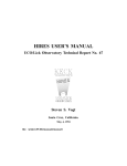
Figure 1: KOSMOS mounted in the Cassegrain Cage of the 4-m Mayall telescope. .......9
Figure 2: KOSMOS Optical Layout........................................................................... 11
Figure 3: KOSMOS imaging field of view in relation to the detector........................... 12
Figure 4: Total spectroscopic efficiency with the blue and red VPH grisms. ............... 14
Figure 5: Blue VPH grism. Scale and resolving power with a hypothetical 1" slit. ....... 17
Figure 6: Red VPH grism. Scale and resolving power with a hypothetical 1" slit. ........ 18
Figure 7: Nominal quantum efficiency curves for the KOSMOS (and COSMOS)
detectors. ............................................................................................................... 19
Figure 8: Location of the Red, Center, and Blue long slits relative to the detector and
field of view. ........................................................................................................... 21
Figure 9: Movement of the image of a central pinhole relative to the detector at
different telescope orientations due to instrument flexure.......................................... 23
Figure 10: Movement of the image of a central pinhole relative to the detector at
different telescope orientations due to instrument flexure.......................................... 24
Figure 11: Movement of the image of a central pinhole relative to the detector at
different telescope orientations due to instrument flexure.......................................... 25
Figure 12: KOSMOS dark slide handle location. ....................................................... 32
Figure 13: The mayall-2 lower left-hand monitor with the necessary KOSMOS windows
shown (NMSL, NGUI, and xterm). ............................................................................ 34
Figure 14: The mayall-2 upper left-hand window showing the KOSMOS status display
(i.e., the KOSMOS Observing Monitor) and the Mayall temperature monitor................ 35
Figure 15: The mayall-2 upper right-hand monitor containing the VNC window of the
KOSMOS DHS. ........................................................................................................ 36
Figure 16: The mayall-2 lower right-hand monitor contains an IRAF xgterm window
and SAOImage ds9 window to permit the observer to examine their data as they are
taken. .................................................................................................................... 37
Figure 17: The NOAO MONSOON Supervisor Layer (NMSL) window shows the
instrument status, countdown clock, detector information, and exposure control. ....... 38
Figure 18: The NGUI window provides for the creation of observing scripts. ............. 39
Figure 19: The xterm window used to execute the scripts created by the observer
using NGUI. ............................................................................................................ 40
Figure 20: KOSMOS Status Monitor window (alias kccd) that shows the filter,
disperser, and slit information, as well as telescope telemetry data. ........................... 41
Figure 21: Mayall environmental temperature display. This is not part of the NOCS and
is not present on the Blanco telescope. .................................................................... 41
Page 6 of 100
C/KOSMOS Instrument Manual V1.7
Figure 22: The VNC DHS window where images are displayed and where observers
can select the Image Root Name (file prefix). ........................................................... 42
Figure 23: NICS…. ................................................................................................ 43
Figure 24: Mayall guider patrol area relative to the KOSMOS field of view. ............... 57
Figure 25: Blanco guider patrol area relative to the KOSMOS field of view. ............... 58
Figure 26: He-Ne-Ar spectra for blue VPH grism, blue-offset slit............................... 77
Figure 27: He-Ne-Ar spectra for blue VPH grism, center slit. .................................... 79
Figure 28: He-Ne-Ar spectra for blue VPH grism, red-offset slit. ............................... 81
Figure 29: He-Ne-Ar spectra for red VPH grism, blue-offset slit. ............................... 83
Figure 30: He-Ne-Ar spectra for red VPH grism, center slit. ..................................... 85
Figure 31: He-Ne-Ar spectra for red VPH grism, red-offset slit. ................................ 87
Figure 32: Location of access ports for slits (top) and filters (bottom). ..................... 92
Figure 33: Mask holder with retaining ring removed . .............................................. 93
Figure 34: Typical multislit mask. ........................................................................... 94
Figure 35: Mask installed in holder. Note black side facing up. ................................. 94
Figure 36: Longslits in holders (left). ...................................................................... 95
Figure 37: Filter in holder (right). ........................................................................... 95
Page 7 of 100
C/KOSMOS Instrument Manual V1.7
Tables
Table 1 - Imaging Zero Points ............................................................................ 14
Table 2 - KOSMOS Filters .................................................................................... 15
Table 3 - Detector Parameters ........................................................................... 20
Table 4 - Recommended Imaging Flat Exposures ............................................ 68
Table 5 - Recommended Spectroscopic Calibration Exposures ....................... 69
Page 8 of 100
C/KOSMOS Instrument Manual V1.7
1 Introduction
KOSMOS is the Kitt Peak Ohio State Multi-Object Spectrograph, a visible-wavelength
spectrograph and imager at the 4-m Mayall telescope at Kitt Peak National Observatory.
This instrument was built to provide a modern, high-efficiency spectrograph for the U.S.
community that meets many of the scientific needs described in the ReSTAR (Renewing
Small Telescopes for Astronomical Research) Report. KOSMOS was commissioned in
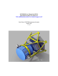
October 2013. Figure 1 shows KOSMOS mounted in the Cassegrain Cage of the 4-m
Mayall telescope.
Figure 1: KOSMOS mounted in the Cassegrain Cage of the 4-m Mayall
telescope.
KOSMOS was built by a partnership between Ohio State and NOAO, and is largely based
on the OSMOS (Ohio State Multi-Object Spectrograph) instrument at the MDM 2.4m
Hiltner telescope. The heritage from OSMOS includes an all-refractive optical design
that enables imaging, longslit, and multi-slit spectroscopy over a wide field, rapid
reconfiguration between observing modes, and the capability to have a wide range of
slits, filters, and dispersers mounted simultaneously.
Page 9 of 100
C/KOSMOS Instrument Manual V1.7
KOSMOS has a nearly identical twin named COSMOS (Cerro Tololo Ohio State MultiObject Spectrograph) at the 4-m Blanco Telescope of the Cerro Tololo Inter-American
Observatory. Except where noted otherwise explicitly, all contents of this manual apply
to both instruments, even if only KOSMOS is named.
Page 10 of 100
C/KOSMOS Instrument Manual V1.7
2 Instrument Characteristics
The Kitt Peak Ohio State Multi-Object Spectrograph (KOSMOS) is an imager and low- to
moderate-resolution spectrograph for the 4-m Mayall telescope that operates from
approximately 3500 Å to 10000 Å. KOSMOS has an approximately 10 arcminute circular
field of view, at a scale of 0.29” per pixel. This same field is available for spectroscopy
with multi-object slit masks. There are presently two VPH grisms, hereafter named the
Blue VPH grism and the Red VPH. Both provide a resolving power of approximately R =
2000 with a 1” wide slit. The nominal wavelength ranges are 3800 Å to 6600 Å for the
Blue VPH and 5800 Å to 9400 Å for the Red VPH grism, although somewhat shifted
wavelength coverage is possible with offset slits.
KOSMOS has an all-refractive design (see Figure 2). The collimator is f/7.9 and contains
five lenses, including a doublet. The first collimator element is 73mm from the telescope
focal surface, which provides ample space for the slit wheel. The collimated beam
diameter is 54mm, and the pupil is located 68mm from the vertex of the last collimator
element. The disperser wheel is coincident with the pupil. The total collimated beam
space is 170 mm and also includes two tilted filter wheels. The camera is f/2.7 and
includes 9 lenses in the form of two triplets, one doublet, and a field-flattener. The final
optical element is the flat window of the CCD Dewar. The full field of view has a radius
of 5.82’. When imaged on a 2048 x 4096 detector with 15-micron pixels, the total field
of view is approximately 100 square arcminutes.
Figure 2: KOSMOS Optical Layout.
The telescope focal surface is at the far left and the detector is at the far right.
KOSMOS may be used with either a relatively blue-sensitive e2v CCD or a more redsensitive LBNL CCD. At present, only the first detector is available. Both devices are
2048 x 4096 arrays of 15 micron pixels. Basic parameters are listed below (section 2.4).
The layouts of the imaging and spectroscopic fields are outlined below (also see Section
2.6).
Page 11 of 100
C/KOSMOS Instrument Manual V1.7
Figure 3: KOSMOS imaging field of view in relation to the detector.
The width of the field is 10’ in the spatial (field) direction.
The normal image display mode (see Section 5.2 for details) has the long axis as the Y
(vertical) axis and the short axis as the X (horizontal) axis. That is, the display is rotated
90 degrees relative to Figure 3.
When imaging with the instrument, the relation between what you see on the ds9
display and celestial coordinates is as follows:
• At PA=90 degrees (KOSMOS default), North is up and East is to the left
• At PA=270 degrees (COSMOS default), North is down and East is to the right
In spectroscopic modes, blue is at the bottom (small Y values) and red is at the top
(higher Y values). (See Section 2.6).
Page 12 of 100
C/KOSMOS Instrument Manual V1.7
2.1 Basic Parameters
Optical Design:
Collimator: f/7.9, 14 degree FOV Double Gauss
Camera: f/2.7, 26 degree FOV Petzval
Grisms: Fixed position, zero net deviation at blaze peak
Filters: In collimated beam, tilted 8° to avoid ghost images
Wavelength Coverage: Full wavelength coverage is 3600 Å – 10000 Å
Field of View: 12’ diameter cropped to 100 sq. arcminutes by detector
Pixel Scale: 0.292 arcseconds per pixel
Operating Modes:
Direct Imaging: KPNO facility 4-inch filters + dedicated blocking filters
Grism Spectroscopy: Blue VPH grism, Red VPH grism, with blocking
filters as required
Disperser Resolution and Wavelength Coverage (see Appendix B):
Blue VPH Grism: R~2100
Blue Slit: 3500 Å-6200 Å
Center Slit: 3800 Å-6600 Å
Red Slit: 4300 Å-7000 Å
Red VPH Grism: R~2100
Blue Slit: 5000 Å-9000 Å
Center Slit: 5800 Å-9400 Å
Red Slit: 6100 Å -10000 Å
Long slits: Facility 0.6”, 0.9”, 1.2”, 1.5”, 3.0" wide. All slits are 10’ long.
Multi-Object Masks: Custom, laser-machined slit masks
Minimum Recommended Exposure Time: 0.01 sec/0.5 sec for accurate
photometry (see section 2.7)
Page 13 of 100
C/KOSMOS Instrument Manual V1.7
2.2 Throughput
2.2.1 I m aging Throughput
Table 1 - Imaging Zero Points
R
Filter
g
ZP [1 DN/s]
27.20
27.23
i
27.08
e/s [0 mag]
5.00e10
5.13e10
4.47e10
Table 1 lists zero points for representative filters on the AB magnitude system. These
measurements were obtained with the e2v detector.
2.2.2 Spectroscopic Throughput
Figure 4: Total spectroscopic efficiency with the blue and red VPH grisms.
The three solid lines for each grism represent the blue, center, and red slit
options. Efficiency includes the instrument, telescope, and atmosphere at Zenith.
Page 14 of 100
C/KOSMOS Instrument Manual V1.7
2.3 Filters
KOSMOS has 2 filter wheels with 6 positions each, of which 1 should be kept open.
Thus, a total of 10 filters can be installed. KOSMOS has a set of 5 order-blocking filters.
These are listed in Table 2. KOSMOS may also be used with any of the KPNO 4-inch
square filters; COSMOS may be used with the CTIO 4-inch filters 1. There are two
important stipulations. First, since the filters are in the collimated beam, any filters that
do not meet specific flatness criteria will distort the wavefront, and thus compromise
the image quality. Second, because the filters are tilted by 8 degrees (to avoid
reflection ghosts), all narrowband filters are significantly blue-shifted. The table below
includes filters that have been tested with KOSMOS; it will be expanded to include CTIO
filters. KPNO filters are also listed on the Kitt Peak web page, where transmission
curves for narrowband filters with the 8-degree tilt are presented when available.
Filter
ID
Filter Name
Table 2 - KOSMOS Filters
Comments
---
GG395
KOSMOS dedicated blocker
---
GG455
KOSMOS dedicated blocker
---
GG495
KOSMOS dedicated blocker
---
OG530
KOSMOS dedicated blocker
---
OG570
KOSMOS dedicated blocker
1584
SDSS g
1585
SDSS r
1586
SDSS i
1590
[O III]
redshifted
Shifts to rest frame. Need to refocus telescope by -500
microns
1564
Ha...
Shifts to red frame H-alpha
1
http://www.noao.edu/kpno/filters/4Inch_List.html and
http://www.ctio.noao.edu/noao/content/ctio-3x3-inch-and-4x4-inch-filters
Page 15 of 100
C/KOSMOS Instrument Manual V1.7
The order sorting filters are dedicated filters, and therefore always available; the other
4-inch filters may be used on other telescopes, so make sure to request them in
advance if they are essential to your program.
We prefer to have the dedicated filters always installed in the instrument, but they can
be removed if your program requires more than 5 additional filters. Filter changes are
normally done only during regular work days, and should have been requested in
advance. Last-minute requests may not be honored if the personnel or the requested
filters are not available.
Page 16 of 100
C/KOSMOS Instrument Manual V1.7
2.4 Dispersers
2.4.1 Blue VP H Grism
Figure 5: Blue VPH grism. Scale and resolving power with a hypothetical 1" slit.
Page 17 of 100
C/KOSMOS Instrument Manual V1.7
2.4.2 R ed VP H Grism
Figure 6: Red VPH grism. Scale and resolving power with a hypothetical 1" slit.
2.4.3 Additional Grism s
The disperser wheel has space for 3 additional dispersers, leaving an open position for
imaging.
Page 18 of 100
C/KOSMOS Instrument Manual V1.7
2.5 CCD Detectors
The table below summarizes basic parameters for both detectors. At present, only the
e2v detector is available. The LBNL detector would see use (when available) for
programs that focus on observation at redder wavelengths. Once a choice is available,
considerations are as follows:
• The e2v detector provides better blue response, but its response is somewhat
less in the red, and decidedly lower in the far red.
• The LBNL is a thicker detector, and therefore has a much higher cross-section to
cosmic rays. [Will add a couple of comparison figures when we have them.]
• The LBNL detector will support nod and shuffle. However, implementation of this
mode is not planned on any particular schedule
• Dewar changes are a day-time operation that must be scheduled in advance, and
which may not be possible on weekends (TBC). The detector or detectors
required for the program must be identified on the telescope time request.
e2v typical QE: -100°C Deep depletion silicon astro process
100%
90%
80%
70%
QE (%)
60%
50%
40%
30%
20%
10%
0%
300
500
700
Wavelength (nm)
-D42 default
900
LBNL
Figure 7: Nominal quantum efficiency curves for the KOSMOS (and COSMOS)
detectors.
Additional detector parameters are summarized below.
Page 19 of 100
1100
C/KOSMOS Instrument Manual V1.7
Detector
Table 3 - Detector Parameters
e2v
LBNL
Read Noise
5 electrons
Gain
0.6 e/ADU
Regions of Interest/Read
time (1x1 binning)
4k x 2k / 46 sec
TBD
TBD/xxx
2k x 2k / 26 sec
1k x 1k /13 sec
4k x 320 /13 sec
Binning
1x1, 2x2, 1x2
Nod and Shuffle?
No
TBD
For most observing programs, the detectors will be operating unbinned (1x1 binning).
This is because the unbinned mode is matched to both the resolution of the
spectrograph and reasonable seeing.
The software supports 2x2 binning and 2x1 binning. The “2x1” mode bins along the slit;
this is potentially of interest to someone trying to take a series of spectra with minimum
readout time, probably also using the 4k x 320 ROI.
Page 20 of 100
C/KOSMOS Instrument Manual V1.7
2.6 Slits
2.6.1 Facility Longslits
Figure 8: Location of the Red, Center, and Blue long slits relative to the detector
and field of view.
The blue and red slits are offset by 160” (25mm physical units at the focal
surface) relative to the central slit. Note that +Y is North at PA=90, and +Y is
South at PA=270. See Appendix E for the physical layout of the slits in the slit
holders.
2.6.2 Custom M ulti-Object Slit M asks
Multi-slit masks can be designed and fabricated for KOSMOS. These are laser-cut from
special shim stock. Users are responsible for designing their own masks (see Appendix
C and links therein for details). There are significant differences between the two
telescopes that affect mask design, as summarized below:
Page 21 of 100
C/KOSMOS Instrument Manual V1.7
•
•
•
•
•
The range of rotator angles on the two telescope is different:
o The available range on the Mayall is 0-180 degrees.
o The available range on the Blanco is 0-360 degree excluding 87-93
degrees.
The plate scales on the two telescopes are slightly different
Note that the instruments are installed so that at a given position angle, the
physical orientation (NSEW) of the instrument is the same on both telescopes.
Because of the first 2 differences, KOSMOS masks cannot be used on COSMOS
(and vice versa)
The Mayall does not have an atmospheric dispersion corrector that covers the full
field of view of KOSMOS, so masks should be designed considering the likely
parallactic angle at the time of observation. The Blanco, in contrast, does have
an ADC with sufficient field of view.
Page 22 of 100
C/KOSMOS Instrument Manual V1.7
2.7 Flexure
The figures below show flexure at two different rotator position angles. In both cases,
the flexure perpendicular to the slit is small. In general, flexure will be <0.2 pixels/hour
in the dispersion direction. For realistic exposure times, this is far below the level that
would degrade resolution, but caution is required if you are trying to measure radial
velocities to better than ~0.1 pixel (5 km/sec or so).
Figure 9: Movement of the image of a central pinhole relative to the detector at
different telescope orientations due to instrument flexure.
Data are for KOSMOS. The points are relative to zenith (“Z”, measured three
times) and correspond to two and four hours East and West at constant
declination, and -30, -17 (orientation for the dome’s white spot), 0, +60, and
+85 deg declination along the meridian. These measurements were obtained
with the instrument rotator at PA=0 deg.
Page 23 of 100
C/KOSMOS Instrument Manual V1.7
Figure 10: Movement of the image of a central pinhole relative to the detector
at different telescope orientations due to instrument flexure.
Data are for KOSMOS. The points are relative to zenith (“Z”, measured three
times) and correspond to two and four hours East and West at constant
declination, and -30, -17 (orientation for the dome’s white spot), 0, +60, and
+85 deg declination along the meridian. These measurements were obtained
with the instrument rotator at PA=90 deg.
Page 24 of 100
C/KOSMOS Instrument Manual V1.7
Figure 11: Movement of the image of a central pinhole relative to the detector
at different telescope orientations due to instrument flexure.
Data are for COSMOS. The points are relative to zenith (“Z”, measured three
times) and correspond to two and four hours East and West at constant
declination, and -85, -60, 0, and +25 deg declination along the meridian. These
measurements were obtained with the instrument rotator at PA=270 deg.The
data should be similar to those in the preceding figure; difference may reflect
differences in the dewar flexure between the two dewar designs.
There is also flexure between the guide probe and the slit; this appears to be roughly
comparable (about ¼ pixel/hour in the direction of changing gravity). Our
recommendation is that you should re-check centering of the object on the slit after ~2
hours.
Note that for both guider-slit and slit-detector flexure, orientation at the parallactic
angle tends to put the direction of maximum flexure along the slit.
Page 25 of 100
C/KOSMOS Instrument Manual V1.7
2.8 Shutter
The shutter is located at the front of the instrument (between the entrance hatch and
slit wheel). It is a model PS-500 from Sci-in Tech with a square, 5” aperture. There are
two carbon-fiber blades that provide even illumination with high accuracy over the
entire field. Exposure times at least as short as 0.01 seconds are possible, although the
accuracy of such short exposures is poor. It is recommended that exposures be kept to
0.5 second, or longer, if photometric accuracy of 1% is required. For short exposures,
repeatability and accuracy across the field are better than the absolute timing accuracy,
which may be off (too long) by as much as 7 msec.
The shutter actually takes about 1 second to open or close; for short exposures one leaf
of the shutter is open while the other leaf follows it and closes; thus, for very short
exposures a narrow slot moves across the focal plane. The time when photons first
arrive at the detector will therefore come several tenths of a second after the nominal
start of the exposure, and this time will vary across the detector (along the length of
the slit). The shutter delays are taken into account when starting the readout of the
CCD. Note that the actual duration of the exposure (exposure to light) is correct and
accurate.
Page 26 of 100
C/KOSMOS Instrument Manual V1.7
3 Proposing for KOSMOS
In order to write an observing proposal for KOSMOS, you should understand the
available instrument configurations (section 2, above). You should also think through
how you will actually observe. In particular:
• Which instrument modes will you need (imaging, longslit, multislit)? Note that
some imaging is required for acquisition, but you don’t need to calibrate these
images.
• If you are doing multislit observations, where will you get the imaging data to
create your masks?
• What filters will you need to acquire your objects, or for any imaging data you
need?
• Once there is a choice of CCDs, is one preferred to the other? Does your
program benefit from switching detectors partway through the run?
• For KOSMOS, which does not have an atmospheric dispersion corrector available,
can you manage to orient your multislit masks so atmospheric dispersion runs
along the slits (more or less)?
• If you require more than one spectroscopic configuration, how will you handle
this? The choices are either to do all configurations at each target setting, or to
observe all targets with one setting, then repeat the targets with another.
Overheads are likely to be somewhat lower with the first approach, but if one
configuration is more important than the others, the second approach may still
be preferable. If you are using both CCDs (once they are available), the second
approach is the only possibility. The mechanisms are highly repeatable, so for
almost all programs, switching configurations for each object is reasonable.
Page 27 of 100
C/KOSMOS Instrument Manual V1.7
4 Observing Preparation
Once you’ve been allotted time, consult the relevant web page(s), for KPNO and CTIO
respectively:
http://www.noao.edu/kpno/observer_info.shtml
http://www.ctio.noao.edu/noao/content/Planning-Executing-Wrapping-your-run-CTIO
Both observatories will ask you to specify the instrument set-up:
http://www.noao.edu/cgi-bin/kpno/OrpForm.pl
http://www.ctio.noao.edu/forms/supportforms/visitor_support.html
In specifying the set-up, consider the following:
• Your request for CCD must match your proposal (once there is a choice of CCD).
• Filter requests in addition to those specified in your proposal may or may not be
accommodated – if there is a conflict with another telescope where the filters
were requested in the original proposal, you will lose out. Also, since the filter
wheels will only handle 5 filters in addition to the standard blocking filters,
requesting too many filters will create support problems.
• Make sure you correspond early with your assigned staff contact if you are going
to observe in multislit mode.
• NOAO may set a limit on the number of masks it will manufacture without cost to
the observer (per night); for the time being we only ask that people be realistic
about how many masks they will plausibly use.
Other recommendations:
• Until we have an alternative procedure, make sure you bring (or have the ability
to download) the mask design files you create, if you are using multislit mode.
• See recommendations for coordinate caches at the respective telescopes
• Download, install, and practice with NGUI, in order to familiarize yourself both
with the process of script creation and the variety of observing parameters
available to you. It is not worth trying to create all the scripts you might use,
however, since they won’t run properly if filter names differ slightly, or
instrument configurations are at all different.
Page 28 of 100
C/KOSMOS Instrument Manual V1.7
5 Observing with KOSMOS
Section 5 (this one) and Section 6 describe the KOSMOS observing procedures in detail.
Please read through them carefully; you may then want to read Section 7 which
provides suggestions for optimizing your observing efficiency.
The software used to control KOSMOS is called the NOAO Observation Control System
(NOCS). The NOCS is a script-based software package, meaning that a script (that has
most likely been created by the observer) performs all of the data acquisition. A script
editor, the NOAO Graphical User Interface (NGUI), is part of the software package,
making it simple to create scripts as you observe. The NGUI software can be
downloaded by visiting astronomers here.
The NGUI is discussed in more detail in section 5.2. NOAO may provide some basic
scripts related to calibrations, but for the most part you will need to create the scripts
you will use. The predefined scripts will be discussed in more detail in the calibration
section (6).
Several computers work together to obtain KOSMOS data. The list below is specific to
KOSMOS, but the arrangements for COSMOS are very similar. Although the observer
should only need to access kosmos and mayall-2 (or mayall-3), we list the full
complement of computers for completeness.
mayall-2 (or mayall-3): A Mac mini computer in the Mayall 4-m control room from which
all programs are launched. The observer should be logged into mayall-2 or mayall-3
using the 4meter account. The password for the 4meter account is available in the
control room or can be provided by Observer Support. Both mayall-2 and mayall-3
have four (4) attached monitors. If you are observing remotely, you will most likely
connect to mayall-2 by a Virtual Private Network (VPN) and display the mayall-2 screens
remotely. (For COSMOS a similar capability is provided through a Linux workstation,
again with multiple monitors.)
kosmos (kosmos-4m): The main computer that runs the NOCS and co-ordinates the
data acquisition for the observer. (COSMOS computers are the same, except named
cosmos-xxx)
kosmospan (kosmospan-4m): The MONSOON pixel acquisition node (PAN) computer.
kosmosdhs (kosmosdhs-4m): The main data handling system (DHS) machine that
ingests data from the PAN, performs various data management tasks, and produces the
final FITS image on disk. This image is transferred back to kosmos-4m and to the
NOAO archive.
In addition to the NOCS, a number of the observing tasks make use of the IRAF image
analysis facility. While the manual specifies relevant IRAF commands for most tasks, a
general familiarity with the software is extremely helpful. Information and tutorials can
be found at http://iraf.net/ .
Page 29 of 100
C/KOSMOS Instrument Manual V1.7
Page 30 of 100
C/KOSMOS Instrument Manual V1.7
5.1 Startup
Most of this section is devoted to starting the observing software, but some additional
tasks are listed at the end -- don't overlook these.
5.1.1 Directory Structure
The NOCS software runs on the computer kosmos (kosmos-4m) at the Mayall 4-m
telescope, but is displayed on the computer mayall-2 or mayall-3. Mayall-2 and mayall3 are Mac mini computers with 4 monitors and a small web camera.
You will operate the instrument logged into kosmos. Normally, you will do any image
processing needed to support your observations on this computer as well (not the
observer workstation). When you are logged into kosmos, your home directory will be:
/home/observer
Type “cd” to return to this if you’re not quite sure where you are. You should also start
IRAF in this directory, since that’s where the login.cl file is located. Some relevant subdirectories are:
/home/observer/exec
/home/observer/bin
/home/observer/data
[observing scripts are created and run here]
[a few specialized commands are located here]
[active data sub-directory]
The “data” sub-directory is actually an alias for
/data2/observer/data/YYYMMDD
where YYYYMMDD is the date of the start of the night. It is re-evaluated whenever you
restart the NOCS (see below) 2. If you need to look at previous nights’ data, you can
navigate using the direct path listed above – just specify the desired night’s subdirectory.
Directories on cosmos are organized in the same way.
2
The data directory on kosmos-4m will change if you restart after local noon. Data are
stored under a new date in the NOAO archive starting at ~9 am, regardless of whether
the NOCS has been restarted. You can specify the directory where new data are stored
from the DHS window; don't do this unless you are sure you know what you are doing.
Page 31 of 100
C/KOSMOS Instrument Manual V1.7
5.1.2 Tasks in the Cage
Before starting the NOCS software, it is important to make sure that the Torrent
controller for KOSMOS is turned on and that the dark slide has been moved to the open
position. Both the Torrent power switch and the KOSMOS dark slide are located in the
Mayall Cassegrain cage. Turning on the Torrent controller must be performed by a
KPNO/CTIO staff member. Normally, the controller is left on during the day, but it may
be turned off if there is a risk of lightning, or because of engineering or maintenance
activities.
The observer is allowed to open the dark slide if they have been instructed; the dark
slide is normally closed by the telescope operator at the end of the night.
The dark slide is located on the far side of the instrument from the cage door, near the
top (see Figure 12). Pull down on the handle slightly and slide in or out. Note that the
slide is somewhat counter-intuitive, in that it is opened by pushing the handle in, and
closed by pulling it out. Confirm that you've set the dark slide correctly using the labels
next to the handle.
Figure 12: KOSMOS dark slide handle location.
In the figure, the dark slide is shown in the open position. Pull down slightly on
the handle (arrow) before you move it in or out.
Page 32 of 100
C/KOSMOS Instrument Manual V1.7
If the NOCS software has been started before the Torrent controller has been turned
on, NMSL window background (see Fig 17, below) will be yellow or orange (this is not
the only reason it can change color, however). You will need to call someone to turn
the controller on in this case. Please see Appendix D, which addresses common
KOSMOS problems and their solutions. If KOSMOS has been started before the dark
slide has been removed, all observations will look like bias frames. The solution is to
open the KOSMOS dark slide.
5.1.3 NOCS Startup
The observer should first logon to either mayall-2 or mayall-3 using the 4meter
account, if this has not already been done (the account password is located in the
Mayall control room). (For COSMOS, login on observer2 as kosmos; get the password
from your support contact.) The steps required to start the NOCS are:
1. Open an xterm window on mayall-2 or mayall-3.
2. On the command line, type the following:
ssh –X –Y observer@kosmos
The observer should now be logged into kosmos as observer and ready to start the
NOCS. In the observer@kosmos xterm window, the observer should then type the
following at the command prompts, waiting for each command to fully execute before
typing the next:
cd
nocs start hardware
nocs start all
If you need to perform other tasks (for example, run IRAF) on the kosmos computer,
open another xterm and issue the same "ssh" command as above, then start IRAF or
whatever else you want to do.
If you are observing with COSMOS, the everything described here and in the rest of this
section, except that the "kosmos" is replaced with "cosmos" in accessing computers.
5.1.4 Shutdow n
To shut down the NOCS at the end of the night, type
nocs stop all
nocs stop hardware
You do not need to be in any particular directory to do this.
The telescope operator will close the dark slide when he/she fills the dewar (on the
Mayall only, the COSMOS dewar does not need to be filled at the end of the night; the
dark slide should still be closed).
Page 33 of 100
C/KOSMOS Instrument Manual V1.7
5.2 User Interface
After KOSMOS has been initialized, a variety of windows will open to enable observing
with KOSMOS. Upon successful completion of starting the KOSMOS user interface, the
lower left-hand monitor should look similar to this:
Figure 13: The mayall-2 lower left-hand monitor with the necessary KOSMOS
windows shown (NMSL, NGUI, and xterm).
The upper left-hand window should look similar to this:
Page 34 of 100
C/KOSMOS Instrument Manual V1.7
Figure 14: The mayall-2 upper left-hand window showing the KOSMOS status
display (i.e., the KOSMOS Observing Monitor) and the Mayall temperature
monitor.
The upper right-hand window should look similar to Figure 14. This display contains
the VNC Viewer that shows the KOSMOS Data Handling System (DHS).
Page 35 of 100
C/KOSMOS Instrument Manual V1.7
Figure 15: The mayall-2 upper right-hand monitor containing the VNC window
of the KOSMOS DHS.
The lower right-hand window should look similar to this:
Page 36 of 100
C/KOSMOS Instrument Manual V1.7
Figure 16: The mayall-2 lower right-hand monitor contains an IRAF xgterm
window and SAOImage ds9 window to permit the observer to examine their data
as they are taken.
Starting with the lower-left screen, these windows contain:
Page 37 of 100
C/KOSMOS Instrument Manual V1.7
1. NOAO MONSOON Supervisor Layer (NMSL): The main instrument status
window with countdown clock, detector information, gain selection, and
exposure control (e.g., Pause, Resume, Stop, and Abort Exposure).
Figure 17: The NOAO MONSOON Supervisor Layer (NMSL) window
shows the instrument status, countdown clock, detector information, and
exposure control. The top image shows it with the text window open, the bottom
image is with it closed.
The appearance of this screen may be slightly different with continuing improvements
to the software. For normal operation, you can hide the upper text window using the
"Options" menu; you can restore it if needed.
Page 38 of 100
C/KOSMOS Instrument Manual V1.7
2. NOAO KOSMOS Spectrograph Mayall 4m Telescope: – Aka NGUI, the
script editor window.
Figure 18: The NGUI window provides for the creation of observing scripts.
Page 39 of 100
C/KOSMOS Instrument Manual V1.7
3. An xterm/terminal window that allows an observer to execute scripts that
were created by the KOSMOS NGUI.
Figure 19: The xterm window used to execute the scripts created by the
observer using NGUI.
The path needed to execute the scripts is /home/observer/exec.
Continuing with the upper left-hand screen, we have the:
Page 40 of 100
C/KOSMOS Instrument Manual V1.7
4. KOSMOS Status Monitor: This window shows instrument and telescope
telemetry.
Figure 20: KOSMOS Status Monitor window (alias kccd) that shows the filter,
disperser, and slit information, as well as telescope telemetry data.
Figure 21: Mayall environmental temperature display. This is not part of the
NOCS and is not present on the Blanco telescope.
Continuing with the upper right-hand screen, we find the:
Page 41 of 100
C/KOSMOS Instrument Manual V1.7
5. VNC KOSMOS-4m:1 (monsoon): The VNC window with the Data Handling
System (DHS) control and image display.
Figure 22: The VNC DHS window where images are displayed and where
observers can select the Image Root Name (file prefix).
Finally, we have the lower right-hand screen, which contains an xgterm window for the
observer to run IRAF and a SAOImage ds9 window to display images. There is one
more screen that is normally minimized, but which can be useful at times:
Page 42 of 100
C/KOSMOS Instrument Manual V1.7
6 . NICS
Figure 23: This NICS shows mechanism status and also allows manual control.
Here, the text window in the upper part has been minimized and the control buttons for
the mechanisms have been enabled (otherwise they would be grayed out).
This is normally minimized (look for it at the bottom of the lower left monitor). If you
open it, it shows you current mechanism status. You can also control the mechanisms if
you open the "Options" menu and select "Enable command buttons". You can then
move the mechanisms by clicking on the position (for the wheels) or entering a number
and then clicking on the mechanism focus button (focus stages).
You can hide the upper text panel from the "Options" menu.
Page 43 of 100
C/KOSMOS Instrument Manual V1.7
5.3 How to Take Data
All data are taken by executing a script that you, or someone else, have previously
created. The script defines the observing parameters, including object name. Scripts are
located in the /home/observer/exec directory. You can practice creating scripts with
NGUI, but scripts created elsewhere may or may not work at the telescope, because the
filter or slit configurations may be different.
5.3.1 Getting Started
At the start of your run, you need to specify some basic parameters. These are
preserved even if you restart the NOCS, so you only need to do this once, or if
something changes.
• In the NGUI window upper left corner, select Options -> Set Project. This allows
you to specify the proposal ID, observer, and telescope operator.
• Then issue the command: nocs set project
• In the VNC window for the DHS, in the window on the upper left, select the
Paths & Files. You can then specify the prefix that is applied to all your data files.
The prefix you specify is followed by a “.” and a file number. Although you can
change the prefix as often as you want, for example to match object names, it’s
very easy to forget to do it every time. We recommend picking a more generic
prefix that you won’t need to change as often, e.g. “raw” or “Night1”.
• Also within the NGUI Options menu are several boxes that can be checked or
unchecked. Confirm that the “Parallelize Mechanisms” and “Include Temperature
Readback” boxes are checked, and the “Include Gain Control” box is NOT
checked. The lamp control boxes are discussed in more detail in the section on
calibrations; for the purposes of startup it doesn’t matter whether they are
checked or not.
It's also helpful to position the various windows in a way that allows you to observe
efficiently; the layout described about is one we have found helpful.
5.3.2 Creating Scripts
A few basic calibration scripts should already be available to you; a list is provided
below. A more extensive set of scripts has not been provided, because they rely on
having all elements with the same exact names in the current configuration and in the
script; since you can only check this by viewing the script in a text editor (or trying to
run it), it's usually quicker to create what you need.
To create a script, select one of the buttons on NGUI (the grayed out options are not
supported).
A new window appears allowing you to select parameters for the script, including both
the script name and the object name. The parameters that are displayed are usually
Page 44 of 100
C/KOSMOS Instrument Manual V1.7
whatever was set when that particular script type was last created. All scripts require
you to specify an object name and a script name. If a script with the same name exists
when you try to create the new script, you will be prompted to over-write it. Do not
over-write a script that is being executed! The available scripts and their purposes are:
• ZERO. This takes a zero (bias) image or images, and therefore has few
parameters. You will probably want zero images for each region of interest mode
with which you are taking data.
• DARK. This takes a dark image or images. For most observing programs, dark
images are not necessary.
• SKY-TWILIGHT FLAT. This will take twilight or sky flats. With the e2v CCD, these
don’t appear to be necessary. They are not expected to be needed with the LBNL
CCD, either.
• DOME FLAT. This will take dome flats; you should plan to take a dome flat with
each disperser/slit/filter configuration you will observe with. See the calibration
section for details.
• TELESCOPE FLAT. This takes a flat using the continuum lamp in the
rotator/guider. It is not very flat, and is not recommended.
• TELESCOPE ARC. This takes spectra using the arc lamp installed in the
rotator/guider. See the calibration section for details. You will want to take an
arc for each configuration you observe with.
• TELESCOPE FOCUS. This takes a series of exposures with the telescope focus
adjusted according to the parameters specified in the script. Focus units are
microns, and a reasonable step size is 100 microns (50 if seeing is good). At the
Mayall, there is a temperature monitoring widget that recommends focus
changes as the telescope truss temperature changes; consult with the operator
for details. Note – there is an option to start the focus sequence at the mid-point
– do not use this as it does not take out focus backlash properly.
• CAMERA SPECTRA FOCUS. This focuses the slit on the detector, using the
camera focus. See the calibration section for more details.
• SLIT/MOS ACQUISITION. This takes an image of the slit or MOS mask (looking
at sky through an appropriate filter), and then another image with the same filter
and no slit. The offsets to get the target(s) seen in the sky image on the slit(s)
can then be determined using an appropriate IRAF script (see below for slit and
MOS acquisition).
• IMAGE. This takes an image or images. For imaging mode, you will normally
want to specify less than the full frame (2k x 2k ROI typically). This script
supports an optional “dither mode”.
• SPECTRA I and II. These take a spectrum or spectra, using a specified
configuration. You will normally want to use the full frame unless you are looking
only at stars or compact objects, in which case the 320 x 4k ROI will save you
Page 45 of 100
C/KOSMOS Instrument Manual V1.7
some readout time. This script also supports an optional “dither mode”, but at
the time of writing the ability to dither along the slit is not fully functional.
Because the script creating windows normally recall parameters from the last
time they were used, the SPECTRA I and II scripts can be used to remember
parameters for 2 different configurations - for example, a red and a blue set-up so that you only need to update object names and exposure times times.
Things that are easy to overlook when creating scripts:
• Don’t forget to specify the object name.
• If you are taking spectra with more than one disperser configuration, check the
disperser, filter, and slit when creating the script. The SPECTRA I and II options
are intended to help out here.
WARNING: Do not create scripts before you come to the telescope with the intention of
using them to observe – proper execution of scripts requires the instrument
configuration used in creating the script to be the same as the instrument configuration
actually present.
5.3.3 Lam p Control
If you click on the NGUI "options" menu you will see two check boxes for lamp control
and lamp prompt.
If the lamp control box is checked, any script you generate will make sure that
comparison lamps in the rotator are turned on or off as appropriate, and also that the
comparison mirror is in the correct position (either "comp" or "thru"). If this box is
selected, the status of the lamp prompt isn't relevant. This does not control the dome
flat lamps!
If the lamp control box is not check, but the lamp prompt box is, then you will be
prompted at the start of any script requiring a lamp (including dome flats); you will
have to use the "enter" key to proceed.
During the night, you will want to have both boxes selected for any scripts you create,
but for scripts you are going to run during the afternoon in series, you probably want
them both unchecked. See the flat and spectral calibration descriptions in Section 6 for
more details.
5.3.4 Nesting Scripts
You can create script files that execute a series of scripts. This is very useful if you want
to set up a series of calibrations in the afternoon that will execute over dinner, for
example. This is less useful for observations during the night – see the warning below.
You could also create a script that observes a series of filters, or both red and blue
spectra. However, if the individual scripts take a while to execute, you may not find you
Page 46 of 100
C/KOSMOS Instrument Manual V1.7
save much time by concatenating them. To do so, in the xterm window, in the “exec”
directory, create your new script file with a text editor, e.g..
vi BigScript.sh
You can then type in the commands for the scripts you want to execute, and then save
the file. You can also include additional NOCS commands (see the calibration section for
some examples). Then save the script. You will need to make the file executable, e.g.,
chmod a+x BigScript.sh
WARNING: Some caution should be used in creating and using nested scripts. In
particular, do not attempt to scripts that are more complex than a sequence of scripts
and NOCS commands. Also, be aware that aborting a script that is running inside a
higher-level script will likely not work properly; there is a good chance you will have to
re-start the NOCS afterward. Consequently, this approach is recommended only for
sequences of observations that will run unattended (such as calibrations over dinner)
and that you are confident will execute correctly.
5.3.5 R unning Scripts
After you’ve created scripts, by whatever means, you should type “rehash” to allow
them to executed just by typing the name, e.g.,
Spectra.sh
If you haven’t done a rehash after the script was created, precede the name by “./”,
e.g.,
./Spectra.sh
You will then see the contents of the script displayed in the xterm as it executes, and
there should be activity in the appropriate windows of the NOCS.
5.3.6 Aborting Scripts
If your script contains only one (or two) exposures, it may be simpler to abort the
individual exposures (use the “Abort” button on the righthand side of the NMSL window
(Fig. 16).
Page 47 of 100
C/KOSMOS Instrument Manual V1.7
If your script is about to finish (minute or two), just let it run to completion, as the
recovery after an abort will take about the same time.
If, however, neither of these apply:
• Type CNTRL-C <cr> in the shell window
• If you are trying to abort during an integration while the countdown is
proceeding
o type CNTRL-C <cr>, then let the integration run to completion, with DONE in
the NMSL window. The script will stop when the integration has finished but
leaves the last integration unterminated in the data system.
o Issue this command in the shell window to terminate the last integration:
ditscmd nohs nohs_endobs <cr>
o In the DHS VNC monitor (see Fig. 22), check that an image processed to
disk.
o You are ready to take data again.
5.3.7 Script M anagem ent
There is more than one way to manage your scripts, and the following should be taken
as suggestions, rather than mandatory:
• It is very convenient to create a master script for your afternoon calibrations.
Note that if you are working in MOS mode, this script may be different every
afternoon, since the MOS masks will be different.
• There is limited advantage to creating all your night-time observing scripts during
the afternoon; you can usually create the scripts (acquisition and observing) for
your next object during the preceding observation. Or you can try to stay ahead
by a couple of objects. Once you are reasonably familiar with the process, you
can probably create scripts while the operator is moving to your next target, but
in general, allow enough time to check your work before saving.
• You can operate either by over-writing the same basic scripts, or by creating a
new script name (or names) for each object. The first approach leads to less
clutter in the exec directory, but you have to be careful not to over-write a script
that is still executing. The second approach fills up the directory with single-use
scripts; you may wish to clean them out every afternoon. You can run into
trouble if you end up with scripts with similar names and forget which one is
current (e.g., TARC_B.sh and TARC-B.sh).
• In either case, don’t forget to specify the object name! Note that for some
actions (e.g., pointing checks or telescope focus) you probably don’t care what
the object was and can leave it as something generic (“Pointing Star”).
Page 48 of 100
C/KOSMOS Instrument Manual V1.7
•
•
•
•
If you are doing more than one spectral configuration, make sure you change all
relevant parameters when you create the script for each configuration.
If you decide to change file prefixes when you change objects (not
recommended, but it’s up to you in the end), remember to do this before starting
execution of a script.
Scripts in /home/observer/sysexec should not be modified or deleted
Scripts in /home/observer/exec are not archival. They may also be modified or
deleted during the day if trouble-shooting is performed. If you want to protect
them during your run, e-mail or copy them. Copying them for safe-keeping to
/home/observer/<yourname> will protect them during your run.
5.3.8 Autom ated Observation Logging (klog)
A program that creates a log of your observations is available. To run it, type “nocs
start klog” in an xterm open on the kosmos (or cosmos) machine. The program then
starts a log for every new observation that appears in the data directory (files created
through ccdproc or other IRAF tasks are not logged). You can add comments; on the
mountain you can automatically enable printing as pages complete.
The pages are also saved in the data directory, so you can re-print them or copy them.
Page 49 of 100
C/KOSMOS Instrument Manual V1.7
5.4 Data
KOSMOS data are multi-extension fits files, where data from each amplifier are stored in
a separate extension (1-2 for e2v, 1-4 for LBNL). The extensions can be combined
using the ccdproc command within the mscred IRAF package.
5.4.1 Data Storage
Data obtained by KOSMOS are simultaneously sent to the NOAO archive and stored
locally in the “data” subdirectory. This is actually an alias for a subdirectory labeled by
date, so each night, if you restart the NOCS, data will be stored in a new subdirectory
(full path: /data2/observer/YYYMMDD). IMPORTANT: if you leaving the NOCS running
continuously, this data directory will not update from night to night. It is possible to
change the directory setting in the DHS VNC window (Paths & Files tab, change both
paths), but we strongly recommend you re-start the NOCS every afternoon instead
(after noon).
Files are identified by a prefix (set in the DHS VNC window, see above) and a file
number. The file number increments with each exposure and is never reset, so every
image will have a unique name.
Because the data are sent to the archive separately, you can delete or process images
in the local directory without losing the ability to recover the raw data later.
Note that it takes a few (typically 6) seconds after the script completes for the data to
be written to disk – you will see a message in the lower left window on the DHS VNC
window when that happens.
5.4.2 Data M anagem ent
For many of the tasks described below, it is very helpful to do some processing on the
data; for simplicity, we recommend that you process all data using the basic steps
below. You need to decide how you want to handle the products of this processing.
There are a couple of options:
• You can over-write the raw data with the processed data. The raw data are
copied first to a sub-directory (default name Raw). (You can change where and
whether the raw data are copied using the mscred parameters (“epar mscred”).)
This is the recommended approach. If you adopt this approach, note that a
command along the lines of "ccdproc Night1*.fits" will process any fits files
beginning with "Night1" that have not already been processed. See below for
more.
• You can instead process data and specify where the processed files are to go
(and what they are named). This requires that you create a list of files to be
processed and another list of processed files before each time you run ccdproc.
If you want to do this, read the ccdproc help.
Page 50 of 100
C/KOSMOS Instrument Manual V1.7
The minimum recommended processing steps comprise:
• Removal of the bias level for each amplifier, using the detector overscan section
• Trimming the result, since the overscan isn't needed
• Combining the outputs from the individual amplifiers into a single image
You are certainly free to perform additional processing, but it is not needed to carry out
any of the observing tasks outlined below. Note also that the processing only affects
the data on the local machine (kosmos or cosmos); data in the archive are stored as
raw data.
To process the data, type:
mscred
epar mscred
View the parameters and confirm that:
backup = once
backuproot = Raw/ [note the /]
instrument = home/observer/kosmos.dat
Exit with :q .
Now type:
epar ccdproc
For the basic processing (merge into a single image), all steps should be set to "no"
except:
Apply overscan strip correction
Trim the image
Merge amplifiers from same CCD
"CCD image type to process" should be blank
Additional relevant settings are:
biassec = !BIASSEC
Page 51 of 100
C/KOSMOS Instrument Manual V1.7
trimsec = !TRIMSEC
(the ! is required)
Overscan removal settings should use the default values, which are listed below. You
can reset these if they appear to have been tinkered with by typing "unlearn ccdproc"
and then going back to "epar ccdproc".
Starting with "Fit overscan interactively" the settings should read
no/minmax/1/*/1/1/3/3/0
If you type "ccdproc *.fits" ccdproc will only process images that haven't been
previously processed. However, it does take time to check the already-processed
images, so this can be rather slow if you've already taken a lot of images that night.
You are therefore better off specifying a small range of images to check/process (or, if
you are doing long exposures, just the single most recent image). For example:
ccdproc Night1.0905*.fits
ccdproc data.08755.fits
If you are an experienced IRAF user you are obviously free to handle your images
differently, but in that case you are relying on your experience and not this manual.
Page 52 of 100
C/KOSMOS Instrument Manual V1.7
5.5 Camera Focus
The camera focus should be checked, and reset if necessary, before doing afternoon
calibrations. The camera focus does have a temperature dependence, of approximately
-10 microns/degree. Focus shifts of ~25 microns will start to affect image quality, so it
is recommended that you re-check focus if the bench temperature (shown on the status
monitor) changes by much more than 2°C. The external ambient temperature provides
some guidance on how the bench temperature might change in the future. You can use
the temperature coefficient to adjust focus without checking (see below), but it is not
recommended you do this for changes >3°C .
To check focus:
• Set up a spectral camera focus script using the narrowest slit you have available.
If you are just re-checking focus, use steps of 25 microns and 7 positions
centered on (or close to) your current focus
• Once you have the images, run ccdproc on them
• Create a list of the images. Note that you can just list the images directly within
the specfocus task, but it's tedious to do and it's easy to make typing errors. It's
easier to create the list in a file using vi or your favorite text editor.
• Run the "specfocus" routine in the "obsutil" package, with the list file as the
source of the input files. Settings ("epar specfoc") as below:
images = <list of images; if it's a file precede the file name with "@", e.g.,
@list1>
focus = KSCAMFOC
slit1 = <lower slit edge, use a value near the middle, like 1000>
slit2 = <upper slit edge, use a value near the middle, like 1050>
Other values should be unchanged from the defaults; when in doubt type
"unlearn specfoc". Also, if you are using the narrow ROI (320 x 4k) use
appropriate values for the slit edges, like 140 and 180.
•
The output should provide a value for best focus. If it is significantly different
from the current nominal focus, do the following:
o Go to /home/logs and open kosmos_camera.conf for editing (note that
the file will be named this way for COSMOS also).
o Change the focus and zero values to the new best focus value and save
the file. This ensures that if you restart the NOCS, the camera will be set
to the new focus
Page 53 of 100
C/KOSMOS Instrument Manual V1.7
•
You must reset the camera to the best focus, whether it's unchanged or a new
value. This is because it's currently set to the value at the end of the focus
sequence. The command to do so is:
testnics camfocus xxxx
where xxxx is the desired focus value. The instrument status display will update
after a few seconds and should show the correct value. (Note - you can also set
focus from the NICS window - see section 5.2.).
You can adjust focus based on the temperature change using the nominal
coefficient of -10 microns/degree. You need to keep track of (record) the bench
temperature for which you measured focus. If the temperature seems to be
changing systematically in a particular direction, and has changed by 2°C or so,
calculate the new focus, and then apply it using
testnics camfocus xxxx
For example, if your focus was 2020, determined at a temperature of 10.0°C,
and the bench temperature is now 8.0°C and declining steadily, change the focus
to 2040:
testnics camfocus 2040
Don't do this in the middle of an exposure, and preferably not in the middle
of an observing sequence.
Page 54 of 100
C/KOSMOS Instrument Manual V1.7
5.6 Pointing and Telescope Focus
5.6.1 P ointing Check
At the start of the night, the observing assistant will point to a moderately bright star,
which should be centered in the middle of the field. You should do the following:
• Create an appropriate "image" script, if you don't have one already. It should
have a short exposure time (perhaps 0.1 sec, but 0.01 sec is acceptable for a
bright star) and an appropriate filter (SDSS r, for example). If you name the
script something like "Pointing" it can be re-used as needed.
• Run the script
• Run ccdproc on the resulting image (after loading the mscred package); this will
create a composite image.
• From the IRAF xgterm:
o Execute "epar kosmos_offset"; you will need to specify the desired
position (e.g., 512, 512 for a 1k x 1k image), the image with the star field,
the rotator angle and perhaps the pixel scale (0.292 if not already at this
value).
o Type ":g"; it will display the field and then ask you to center the star. If
the star image is not too badly saturated, center the cursor on the star
and type a; if it is saturated center as best you can and type m.
• Give the resulting offset values to the operator. There is no point in trying to
center better than a few arcsec for this purpose, so it is not necessary to iterate
these steps.
It may be convenient at times to re-zero the telescope coordinates (for example, if you
are working in a particular area of sky away from zenith); in that case follow the same
procedure. If you are observing the first night the instrument is installed, the operator
may need to do additional pointing checks; just repeat the process above.
The procedure for COSMOS may not be identical from the telescope operator's point of
view, but what you have to do with the instrument will be the same: advising the
operator when the star is centered.
5.6.2 Telescope Focus
The telescope focus script will take a single image, where the telescope focus is
incremented and the charge is shifted along a column (Y axis for e2v, X axis for LBNL),
with an extra offset for the final focus setting. You need a star or stars that are bright
enough to give good profile measurements, but not so bright that you need a really
short exposure to avoid saturation, because you want to average the seeing somewhat.
Exposure times in the few second range are optimal.
The image is analyzed using the "starfocus" routine in the "obsutil" package. Settings
for the routine are (use "epar starfoc" to access them):
Page 55 of 100
C/KOSMOS Instrument Manual V1.7
images = <image with focus sequences>
focus = 1x1
fstep = <focus step, e.g., 50 or 100>
nexposure = <number of exposures, e.g., 7>
step = <step set in script, in pixel, e.g., 30>
direction = +line
gap = end
coords = mark1
You can also tinker with the measurement parameters further down if you want and
have an idea of what you are doing, but it's not essential. If you want the FWHM in
arcsec, the pixel scale to use is 0.292.
Before running starfoc on the image you should run ccdproc on the image.
When you run the routine, it will display the image and you should use the "m" key to
identify the starting image of the sequence, for one or more stars on the display. Avoid
stars that are saturated, overlapping with other stars, or that run off the edge of the
field. Then type "q" to exit and see a display of focus parameters.
You can re-run the routine omitting or adding stars to see if you get a better result.
There is a "focus widget" [at the Mayall, at least] than monitors telescope truss
temperature and recommends focus adjustments. You can make use of this to tweak
the focus, but you will likely want to re-check focus if the temperature has changed by
a large amount, if the seeing has gotten better, or if you're concerned that the correct
focus has drifted.
Page 56 of 100
C/KOSMOS Instrument Manual V1.7
5.7 Guiding
The telescope operator will select and acquire guide stars. You don't need a guide star
for focus checks or pointing checks, but it's recommended for all other observations.
The usable field for the guider is shown below. IMPORTANT: It may in fact be
possible to observe spectra with the guide probe inside the vignetted area, since the
slits only occupy a portion of the focal plane. If the probe is vignetting the imaging
field, you will see its shadow in the acquisition image, and will be able to see whether it
is occulting your slit or slit mask. If it is not, you can take spectra.
Figure 24: Mayall guider patrol area relative to the KOSMOS field of view.
Selection of guide stars within the gray rectangle can cause the guide probe to
vignette the KOSMOS field. The size of the region that leads to vignetting is
somewhat conservative, particularly for longslit spectroscopy. At PA=90 deg, N is
+Y and E is +X.
Page 57 of 100
C/KOSMOS Instrument Manual V1.7
Figure 25: Blanco guider patrol area relative to the KOSMOS field of view.
Selection of guide stars within the lower region can cause the guide probe to
vignette the COSMOS field. The size of the region that leads to vignetting is
somewhat conservative, particularly for longslit spectroscopy.
Page 58 of 100
C/KOSMOS Instrument Manual V1.7
5.8 Longslit Acquisition
Longslit acquisition can be done using three IRAF scripts, described below. The basic
process performed by the acquisition consists of taking an image through the slit you
want to observe with, followed by an image of the field you want to observe. Guiding
must be on! The observations can be done with any filter, not necessarily the blocking
filter for your spectra.
For most acquisition, the script to use is "koffset1". In the IRAF xgterm, type
epar koffset1
The file prefix needs to match what you are using for the acquisition images; if you
keep the same prefix all night or all run you won't need to change that often. The file
number is for the first file of the pair you observed, and must include any leading zeros.
Then type ":g"
The script will bring up the slit image and ask you to identify the place on the slit where
you want the object. Type "k" to determine an accurate centroid perpendicular to the
slit, and then type "q" to exit; you can repeat the centroiding if needed before quitting.
The position along the slit is determined by the cursor position; you may want to zoom
the image to position it precisely.
Now your field will be displayed. Put the cursor on the object you want to observe and
type "a" to centroid, or type a space to just record the cursor position (not
recommended, use only if you can't centroid your object for some reason). Then type
"q" to exit.
The script will now give you offsets in RA and Dec, which you should communicate to
the telescope operator. The telescope will perform the offset, with the guide probe
compensating for the motion. If the offset is large, it may push the guide probe outside
its allowable range, so it will not move to compensate. In this case, the operator needs
to find another guide star.
Unless you have done a very small offset, it is highly advisable to repeat the acquisition
sequence. Take the images and re-run the koffset1 script as above. Note that if you are
almost in the correct position, and if your object is not too faint, it will likely appear
through the slit in the slit image. If you type "j" when looking at the slit image, while
running the script, you will see how it is centered along the slit; the counts you see
should be comparable to the peak counts in the field image if you are close to being
centered. (Note that they are not likely to equal the peak, because of the way the IRAF
algorithm works.)
Page 59 of 100
C/KOSMOS Instrument Manual V1.7
The other two scripts that can be of assistance with acquisition are "kosmos_offset" and
"slitmove".
"kosmos_offset" allows you to handle offsets in situations where you don't have a slit
image. It can be useful in moving around in an imaging field. In particular, you need to
specify the position you want to move to (X and Y). You must also specify the rotator
position angle; the pixel scale may need to be entered as well - use 0.292 as the value.
Then type "g" and the image will be displayed for you to centroid on your target; you
will again get offsets for the telescope operator.
The third script, "slitmove" is used to offset between the nominal longslit positions - the
command is
slitmove <current> <new>
where the two positions can be "blue", "center" "red". So if you are currently at the
blue slit position and want to go to the center slit, you would type
slitmove blue center
Important! This offset is approximate, but will get you close to the correct position;
you must re-acquire the object on the new slit.
Page 60 of 100
C/KOSMOS Instrument Manual V1.7
5.9 Multi-slit Acquisition
The data for multi-slit acquisition are taken in the same way as for longslit acquisition,
but the subsequence procedure is quite different. You must acquire images using the
2k x 2k ROI, and then process them with ccdproc.
You should also have copied the .kms files associated with your masks to the KALIGN
sub-directory. You may find it convenient to open a separate xterm to kosmos for mask
alignment only (read on, and you'll see why).
Type:
cd
cd KALIGN
python kalign.py <mask.kms> <maskimage.fits> <fieldimage.fits>
where mask.kms is the file for the mask you are trying to align and the two images are
the images taken through the mask and without the mask respectively. Since you are in
the KALIGN directory, you must specify the full path names for the images - these will
be of the form:
/data2/observer/yyyymmdd/XXXXXX.fits
Alternatively, you can copy the images to the KALIGN directory, but this is generally
more time consuming.
Note that if you have a dedicated xterm for mask alignment, you recover and edit the
command using the up-arrow key, and thus don't need to type in the path name every
time you run the command.
The command will open a new ds9 window (unfortunately) and display the mask image.
You will be prompted to select alignment boxes on the image; you do not need to select
all of them (for example, if one of the alignment stars is saturated, you may want to
skip it). After you are done with the selection, the field image is selected and you will
be prompted to select the matching alignment stars, in the same order.
Once you are done, the script will output values for RA and Dec offsets and rotation.
The RA and Dec offsets can be done with the guider in "follow" mode, but the rotational
adjustment doesn't support this, so you are normally better off performing the
rotational adjustment with the guider off, then re-acquiring the guide star.
You will almost certainly need to repeat the procedure; you don't need to take another
mask image if you do.
Page 61 of 100
C/KOSMOS Instrument Manual V1.7
At the time of writing, neither telescope has a working fine encoder, so it's not possible
to set the rotator to better than the nearest 0.1 degree. On the Mayall, we have found
that setting the rotator to the nominal mask PA plus 0.1 degree will get you within
measurement errors on the rotational adjustment. On the Blanco, there is not
(currently) a single offset that works for all rotation angles.
Once you are done, you should close the ds9 window you had open for IRAF
reductions; the window created by kalign should work, but if it doesn't , close that as
well and open a brand-new ds9 window for use with IRAF.
Note: if you just type
python kalign.py
you will see a description of the command options.
You can run the alignment procedure from a different directory (e.g., the data
directory) if you specify pathnames appropriately and/or locate the .kms files
differently; the approach described here works as efficiently as any alternative.
Page 62 of 100
C/KOSMOS Instrument Manual V1.7
5.10 Imaging Acquisition
Acquisition for imaging is performed in the same way as for the initial pointing zero
determination (3.4, above). If you are doing long exposures, or working with
narrowband filters, you may want to position the telescope using short exposures
through a broadband filter. If you are only interested in a single object or a small area,
you can generally skip the pointing check and just start observing.
Page 63 of 100
C/KOSMOS Instrument Manual V1.7
5.11 Observing
Once you have properly centered the object or field, you can then execute the prepared
script. You can verify that you are using the configuration you really wanted by looking
at the status display.
Unless this is a very short observation, this is a good time to make sure you have the
scripts you need for the next observation – but remember that you should not overwrite a script that it is in the midst of execution.
Page 64 of 100
C/KOSMOS Instrument Manual V1.7
6 KOSMOS Calibrations
Most calibrations can be carried out in the afternoon, so you don't use much of the
night observing light bulbs. This is practical because instrument flexure is modest (see
Section 2.7), and because the mechanisms are extremely repeatable. There are two
cautions, however:
• If you are trying to get precise radial velocities, it may be helpful to take arc
spectra before and after observing each object.
• Flexure can introduce low-level effects into flat fields in the red; if you are trying
to achieve very high signal to noise (>100) you may need to take additional
steps.
Page 65 of 100
C/KOSMOS Instrument Manual V1.7
6.1 Calibration Plan
Except as noted above, the calibration images you need are as follows:
6.1.1 I m aging Calibrations
For calibrating direct imaging, you need:
• Zero (bias) images
• Flat field images in each filter being used for imaging
If you are doing direct imaging only for the purpose of acquisition, you can omit the
calibrations, but unless you are absolutely sure of this, you might as well acquire the
calibration images.
Calibration images should be obtained in the same formats (ROI: region of interest) as
the science images.
In addition, during the night you will likely want to observe standard star fields.
6.1.2 Spectroscopic Calibrations
For calibrating spectra, you need:
• Zero (bias) images
• Flat field images for each configuration where you plan to take spectra. Thus, if
you are planning to observe through 5 multi-slit masks with both red and blue
dispersers, you must take a total of 10 flat fields.
• Arc spectra for each configuration.
Again, during the night you will want to observe spectrophotometric standards.
Page 66 of 100
C/KOSMOS Instrument Manual V1.7
6.3 Bias (“Zero”) Images
You create bias images using the ZERO script. Since there are no photons involved, the
only parameters you need to specify are the number of images (10 is a good number),
binning (1x1, 2x2, 2x1) and the region to be read out (1k x 1k, 2k x 2k, 320 x 4k, full
frame [2k x 4k]).
Page 67 of 100
C/KOSMOS Instrument Manual V1.7
6.4 Flat Fields
All flat fields should be done with the dome flat. Someone from the day crew will
position the telescope for you, pointed at the "white spot". The dome lights should be
off and the shades in the control room should be pulled down before taking dome flats.
The dome flats are controlled either by switches on the telescope console or a gui on
the observer's computer. Ask the person doing the instrument start to show you the
switches. These control a high/low setting and an intensity.
4.4.1 I m aging Flats
Imaging flats are normally done with the low lights, and usually with the intensity
setting about halfway (25). Experiment with the exposure times, but normally you
should be taking ~5-20 seconds and getting ~50,000 counts. Stay under 100,000
counts. Some recommended settings follow. If you are using the GUI to set the lamps,
52 units is ~100% and 24 units is ~50%.
The dome flat lamps are not controlled by the scripts created by the NOCS, so if you
are doing flats with various lamp settings, you need to enable the prompts and adjust
the settings for the individual flat sequences.
Filter
Table 4 - Recommended Imaging Flat Exposures
Lamp setting
Exposure
SDSS g'
Low, 52 units
10 sec
SDSS r'
Low, 52 units
15 sec
SDSS i'
Low, 52 units
20 sec
Hα (all filters)
High, 24 units
10 sec
[O III] (all filters)
High, 52 units
2 sec
These recommendations apply to 1x1 binning; if you are taking data with different
binning you should reduce exposure times by the appropriate factor (2 or 4) or adjust
lamp intensities. Note that flux is not proportional to the numerical intensity setting!
6.4.1 Spectroscopic Flats
Spectroscopic flats are done with the high illumination and maximum intensity.
Recommended exposure times for 3 pixel slits are given below:
Page 68 of 100
C/KOSMOS Instrument Manual V1.7
Type
Table 5 - Recommended Spectroscopic Calibration Exposures
Red disperser
Blue disperser
Flat (high,max int)
7 sec
40 sec
Arc
5 sec
120 sec
Exposure times for flats scale inversely with slit width (less time for wider slits).
Normally 10 images/configuration is reasonable.
It does no harm to take a sample image or two before setting up a complete calibration
series.
NOTE: If you are creating scripts to be run in sequence, unattended, turn off the lamp
control and lamp prompt options in NGUI before creating the scripts (and turn them on
again when you are done). Otherwise you will come back from dinner and find the
whole sequence waiting for a prompt.
Page 69 of 100
C/KOSMOS Instrument Manual V1.7
6.5 Wavelength Calibration
Wavelength calibrations are set up doing the TELESCOPE ARC scripts. Arcs are
observed by moving a mirror in the rotator into the beam, which sends light from the
arc lamp into the instrument. The field of view of the comparison system is smaller than
the KOSMOS FOV, but close enough to be useful for most purposes.
Recommended exposure times are shown in the table above. Note that these do not
scale with slit width, because the lines are unresolved.
NOTE: If you have the lamp control enabled in NGUI, scripts that you create will move
the mirror in and out and turn the lamps on and off as necessary. This is normally a
good thing, but if you are stringing together a series of arc scripts, it wastes time. So
for those situations only turn the lamp control and prompt off.
Then, in the higher-level script within which you nest your comparison scripts, include
the pre-existing COMPSTART.sh and COMPEND.sh scripts to start and end the
sequence. Alternatively, you can have someone from observer support set the lamps
and mirror as needed.
If you need to get arc spectra while observing (for example, because you are trying to
get precise radial velocities), you can run arc scripts at any position of the telescope.
However, there scripts should be created with the lamp control on, so that things are
positioned correctly and the lamps are turned off at the end of the arc observation.
NOTE FOR ADVANCED USERS: The commands to control lamps, rotator mirror, etc.
from the observer's xterm are all of the form:
testntcs <item> <command>
where the "item" is something like "gcccompb" for comparison lamp B, "gccmirror" for
the rotator mirror and "command" is a position or status, like "thru" or "on". These
commands are useful to have in reserve during the afternoon; during the night the
telescope operator can set these items for you more quickly.
6.6 Standard Stars
Lists of standard stars can be found on the KPNO web site:
http://www-kpno.kpno.noao.edu/Info/standard_catalogs.html
Some additional sources of information are listed below. They are current at the time of
this writing.
6.6.1 I m aging (P hotom etric) Standards
Additional sources beyond what's listed on the KPNO catalogs page include:
Page 70 of 100
C/KOSMOS Instrument Manual V1.7
http://www.gemini.edu/?q=node/10445
6.6.2 Spectrophotom etric Standards
Additional sources beyond what's listed on the KPNO catalogs page include:
http://www.gemini.edu/sciops/instruments/gmos/calibration/spectroscopic-stds
http://www.eso.org/sci/observing/tools/standards/spectra/stanlis.html
http://www.astronomy.ohio-state.edu/MODS/Calib/index.html#specphot
The standards listed on these sites are mostly the same; the last two sites include
finding charts.
Page 71 of 100
C/KOSMOS Instrument Manual V1.7
7 Efficient Observing with KOSMOS
This section is intended to help observers minimize overhead time at the telescope.
While a couple of minutes here and there may not look like much, if you observe a
dozen objects per night (including standards) and waste a couple of minutes on each
one, that’s potentially one more target you didn’t get to observe that night. The
following suggestions are intended to help minimize this wasted time.
7.1 General Planning
A few things to keep in mind when planning the night:
• The dome is often the slowest thing involved in a slew; this is especially true if a
large rotation is involved, as may be the case if you are pointing relatively close
to the zenith. Note that you can get comparison (arc) spectra while the dome is
moving, if you have a program that requires them (many will not).
• If you are using the instrument rotator to match the slit to the parallactic angle,
see if you can organize your observations so that you don’t have to go to zenith
before each observation to set the rotator. Small rotations (few degrees) can be
done without going to zenith, but on the other hand small rotations won’t affect
your spectrophotometry anyhow. This is a concern primarily for KOSMOS.
• Make sure you’ve submitted your coordinates in advance, or give them to the OA
early to input.
• If you are going to observe with an offset slit (e.g., “blue long slit”), make sure
you use that position to zero the telescope pointing. If you are using more than
one slit position, it’s most efficient to always start with the slit for which you
zeroed the telescope pointing.
• Use the smallest reasonable region of interest for each step. This can save you
up to ~30 seconds/image, and can therefore cut telescope time used by 2-3
minutes per object. Note that the short-slit spectral region (320x4k) is ~90
arcsec long, which should be more than enough for point sources and compact
targets. For most long-slit acquisition, 1k x 1k should be enough.
• It is always tempting to look at the last image before slewing to the next target.
Recognize that this costs time, and decide for yourself whether you gain
anything by doing this.
7.2 Step by Step Observing
1. Once the shutter closes on the current observation, you can start slewing to the
next position. If you are using KOSMOS and need to adjust the rotator, that next
position is the zenith. If you are not changing the rotator, skip to step 3.
2. At the zenith, the OA will go into the cage and adjust the rotator. For long slit
observations, he/she can set it to the required accuracy in the cage; for MOS
Page 72 of 100
C/KOSMOS Instrument Manual V1.7
observations it will need to be tweaked from the control room but this can be
done away from zenith.
3. Slew to the target. If you need to tweak the rotator, the OA can do it now (larger
adjustments are possible with COSMOS). Also, the OA can identify a guide star
and direct the guide probe to move to that position. Unless it’s a very short slew,
both the rotator and guider will be where they are needed by the time you get to
the target.
4. If you are carrying out a program where you really need to get an arc spectrum
at the position of the telescope, start the rotator mirror moving to the
comparison position. Don’t do this unless using night sky lines for zero-point
adjustments is really not sufficient. If you can skip this, go to step 7.
5. Take an arc spectrum. If you aren’t using a generic arc script (for example, you
want the object name in the header), define the script beforehand!
6. Move the rotator mirror back to the “through” position. If the arc script is set up
with mirror control enabled, this will be automatic. [Note – the script will also
move the mirror into the comparison position, but it’s preferable to do that
manually while the telescope is slewing, and then start the script once the
telescope is on target.]
7. Once the telescope has completed the slew, (and, if necessary, the rotator mirror
is back in the “through” position) the OA can verify that the guide star is visible.
This can be done once the dome is close to its final position, even if there is
some vignetting.
8. Assuming the telescope is pointing fairly reliably, the OA should move the guide
star to the center of the guider field and then lock on it (turn on guiding).
9. Now execute the appropriate NOCS acquisition script. Again, if you aren’t using a
generic script, prepare it beforehand.
10. Run ccdproc on the images; you will save a few seconds if you process each
frame of the sequence once it’s written to disk.
11. Now run the appropriate alignment script (kalign for MOS, koffset for long slit)
12. Give the resulting offsets to the OA.
13. If you don’t need to check the result, skip to step 15. In general, it’s
recommended that you check the alignment if the offset was >10 arcsec or
involved a change in the rotator angle of any size.
14. If you want to recheck the alignment, take an image of the field only. You can
use the slit image you took on the first iteration. Go back to step 11. NOTE: the
long slit alignment script currently doesn't support this, you have to take the slit
image right before the field image.
15. Now you are ready to take spectra! Run the spectra script (which you should
have prepared beforehand).
Page 73 of 100
C/KOSMOS Instrument Manual V1.7
16. It is recommended that you recheck the alignment every 90-120 minutes. Since
there is both flexure between slit and detector and slit and guider, you need to
get both the slit and field images. That is, go back to step 9. You should find that
any offsets are small. If you ran an arc spectrum at the beginning of the
observation, you may want to take another at this point. See steps 18-20 if you
really want to do this.
17. Once you have finished with the spectra, you are done – go to step 1, for your
next object, unless you need to get an arc spectrum, in which case continue with
the next steps.
18. Advise the OA, who needs to turn off the guiding.
19. Execute the arc script (it should move the rotator mirror for you, both in and out,
but if you didn’t set it up that way, have the OA move the mirror and then start
the script once the mirror is in place; this is less efficient, obviously).
20. If you are done with the object, go to step 1 for the next object. If you are not
done, have the observer turn the guider back on once the guide star is visible.
Then go back to step 9 or step 15, depending on whether the alignment needs
to be checked.
Page 74 of 100
C/KOSMOS Instrument Manual V1.7
Appendix A: KOSMOS FITS Header
Page 75 of 100
C/KOSMOS Instrument Manual V1.7
Appendix B: Calibration Lamp Spectra
The images in this appendix are organized according to slit position and disperser, 4
panels for each configuration:
Page 76 of 100
C/KOSMOS Instrument Manual V1.7
Figure 26: He-Ne-Ar spectra for blue VPH grism, blue-offset slit.
Page 77 of 100
C/KOSMOS Instrument Manual V1.7
Page 78 of 100
C/KOSMOS Instrument Manual V1.7
Figure 27: He-Ne-Ar spectra for blue VPH grism, center slit.
Page 79 of 100
C/KOSMOS Instrument Manual V1.7
Page 80 of 100
C/KOSMOS Instrument Manual V1.7
Figure 28: He-Ne-Ar spectra for blue VPH grism, red-offset slit.
Page 81 of 100
C/KOSMOS Instrument Manual V1.7
Page 82 of 100
C/KOSMOS Instrument Manual V1.7
Figure 29: He-Ne-Ar spectra for red VPH grism, blue-offset slit.
Page 83 of 100
C/KOSMOS Instrument Manual V1.7
Page 84 of 100
C/KOSMOS Instrument Manual V1.7
Figure 30: He-Ne-Ar spectra for red VPH grism, center slit.
Page 85 of 100
C/KOSMOS Instrument Manual V1.7
Page 86 of 100
C/KOSMOS Instrument Manual V1.7
Figure 31: He-Ne-Ar spectra for red VPH grism, red-offset slit.
Page 87 of 100
C/KOSMOS Instrument Manual V1.7
Appendix C: Multi-Slit Mask Design
When designing multi-slit masks, there are several considerations, including differences
between the two telescopes.
C.1. Basic Considerations
Slits can, in principle, be placed anywhere in the imaging field of view of the
instruments. However, slits that are displaced significantly in the dispersion direction
may produce spectra that are missing a relevant portion at one end. Also, the VPH
gratings' efficiency curves are strongly position dependent, so a blue-shifted slit will also
have the peak efficiency blue-shifted. This can be advantageous in long-slit mode (see
discussion of offset slits, above) but may be less desirable in multi-slit mode.
In general, therefore, we recommend restricting slits to within a rectangle roughly 5 x
10 arcmin.
In addition, mask layout should allow for alignment stars. Square boxes are designed
into the mask, centered on relatively bright stars, which are used to check mask
alignment. While 2 stars are, in principle, all that is needed, we generally recommend 35 stars, to provide some redundancy. The alignment stars should be distributed widely
over the mask to provide optimal alignment. Note that the alignment boxes do produce
spectra when observing through the mask, so you must be careful to avoid interference
with science slits.
C.2. KOSMOS Constraints
The Mayall rotator is capable of rotation over position angles from 0 to 180 degrees. Do
not design masks for position angles between 180 and 360 degrees.
The only available atmospheric dispersion corrector on the Mayall has a field of view
substantially less than 10 arcminutes, and the guide probe needs to work within this
field when the ADC is used. Thus use of the ADC in multi-slit mode is generally
impractical. You should therefore plan to observe close to zenith, or else design masks
to be used at a position angle close to the parallactic angle of the observations.
C.3. COSMOS Constraints
The Blanco rotator is capable of rotation over a larger range than the Blanco, but has a
zone of exclusion between 88 and 92 degrees.
Also, the atmospheric dispersion corrector available on the Blanco has a field of view
large enough to allow use of the full field and the guider. Its use is therefore
recommended.
Page 88 of 100
C/KOSMOS Instrument Manual V1.7
C.4. Mask Design
The program currently recommended for mask design is adapted from the program
used for OSMOS. It is a very basic program, and may eventually be replaced by
something with greater versatility.
The program will only run on Linux-based computers and older Macs. This is because it
relies on the ESO "Skycat" utilities, which is no longer being updated and thus is
incompatible with recent versions of OSX.
Information on the mask design software can be found at:
http://www.ctio.noao.edu/~points/CKOSMOS/ckosmos_mos.html
The web page includes links to download the KMS software and the ESO SkyCat tool. A
link to a Gerber viewer program (also free) is included at the end; this lets you view
your mask designs.
Page 89 of 100
C/KOSMOS Instrument Manual V1.7
Appendix D: Basic Troubleshooting
D.1 Problems with Photons
Problems and solutions:
• No light on images. Check for the following:
o Is the dark slide open? Unfortunately, there's no way to check without
going out to the cage, but if you were seeing light previously, the dark
slide will not have closed spontaneously. That is, this is a start-up
problem, not a problem in the middle of the night.
o Is the rotator mirror in the correct position? For arcs, it should be in the
"comp" position (check the instrument status display); for any other
image, including flats, it should be in the "thru" position. This can occur if
you have disabled lamp control for a script, and then did not set the lamps
and mirror manually.
o Are the telescope mirror covers open?
o Is the detector operating properly? Check for errors in the NMSL window.
• Images are saturated. Usually a problem if you were trying to take spectra.
o Check that a slit (or mask) is in the beam, and not the open position (see
instrument status display)
o For imaging flats, check that dome flat lamp is set correctly (usually, on
low)
• Spectra badly out of focus. Did you run a camera focus script and forget to
reset the focus afterward? Check that the focus displayed on the instrument
status display is correct, and if not, set the correct value (see section 5.5).
D.2 Problems with Electrons (Including Instrument Start-Up)
Many problems can be solved by stopping and starting the NOCS (see section 5.1.4 and
5.1.3 respectively). However, not all problems are best solved this way, though
stopping/restarting is a good generic solution. Specifically:
• NMSL display window shows orange text box background. The detector
computer is in simulation mode, and the detector is not being read out. If the
problem is a communications issue, stopping and restarting the NOCS may cure
it. If there are problems with communications links, issuing the command
./bin/fixlink
before issuing the NOCS startup commands may solve the problem. If not, the
controller electronics may be powered off; call electronics support for assistance
in checking this and for further troubleshooting if required. Relevant procedures
are listed in the operations manual (Section 4.2); as these require manipulation
Page 90 of 100
C/KOSMOS Instrument Manual V1.7
•
of the Torrent controller and other electronics, users should not attempt these on
their own.
Error messages in NMSL window. Usually accompanied by inability to take
data. If this occurs, try issuing the command
nmslReset
•
•
•
and see if the error messages stop and you can take data. Again, if this doesn't
solve the problem, call electronics support for help.
Readout time counter runs through zero and turns red and negative.
Stop and restart the NOCS. Note that if it does not turn red it will probably
correct itself; don’t restart the NOCS until you verify you cannot take data
(usually a bias frame is a good, quick test).
Image appears to read out normally, but never appears in the data
directory. The image may be hung up in the DHS. Sometimes taking another
image (try a bias as that's quick) will push the image through. If not see the
NEWFIRM troubleshooting suggestions referenced in D.3, below.
Mechanism error. This is infrequent, but if a mechanism has stalled, you can
reset it using the command sequence:
cd ~/bin
change_hardware
cd ~/exec
If the mechanism continues to malfunction, you need to call for assistance as
mechanism stalls should be isolated and infrequent.
D.3 Problems Not Covered Above
If simple software re-starts do not work, power-cycling the instrument and detector
electronics may be necessary. The observer should not do this on his/her own! Call for
assistance if someone qualified is not present already.
Try the following resources:
• Mosaic manual, Appendices F and G:
http://www.noao.edu/kpno/mosaic/manual/
• NEWFIRM manual, Appendix:
http://www.noao.edu/ets/newfirm/documents/NEWFIRM_user_rev3.4.pdf
Use with caution. As noted above, stopping and restarting the system will solve most
problems and is often quicker than trying to check through the documentation to find a
more focused solution.
Page 91 of 100
C/KOSMOS Instrument Manual V1.7
Appendix E - Filter and Mask Changes
This information is included for completeness; observers are not expected to perform
mask or filter changes. Filter changes are normally performed only during the day;
mask changes can be carried out at night (by the telescope operator, but the observer
may be able to help).
Filters or multislit masks should be installed in holders. Longslits are pre-assembled into
holders, so it's a matter of selecting the longslits to be installed.
Filters are installed in holders by the day crew; since there are spare filter holders, any
filters you may have requested should be already installed in holders. At the Mayall,
they will be kept in the loading room (old plate loading room outside the control room).
Access to the instrument for this purpose is shown in the figures below:
Figure 32: Location of access ports for slits (top) and filters (bottom).
Page 92 of 100
C/KOSMOS Instrument Manual V1.7
A disassembled multislit mask holder is shown below; it consists of the holder itself and
a retaining ring that clamps the mask into place.
Figure 33: Mask holder with retaining ring removed .
The 4 clamps can be seen around the inner edge of the holder. Alignment pins
can also be seen at approximately the 6, 11, and 12 o'clock positions.
The KOSMOS masks are cut from stainless steel shim stock that is coated black
on one side. One such mask is shown in Figure 34. COSMOS masks are cut either
from aluminum shim stock that is blackened on both sides, or a thin carbon fiber
sheet. The general appearance for the COSMOS masks will be similar to those for
KOSMOS, except that neither side will be shiny.
The black side of the KOSMOS masks faces the collimator, to reduce ghost
images. While both sides of the COSMOS masks are black, the alignment pins in
the mask holders ensure that the orientation is always correct.
Page 93 of 100
C/KOSMOS Instrument Manual V1.7
Figure 34: Typical multislit mask.
The black side of the mask is facing the detector, not the telescope secondary,
when installed in the instrument (see Figure 35).
Figure 35: Mask installed in holder. Note black side facing up.
Page 94 of 100
C/KOSMOS Instrument Manual V1.7
A longslit holder is shown below. These are permanently configured, so all that needs
to be done for use is to installed the selected holder(s) into the instrument. Filters are
installed by daytime support staff.
Figure 36: Longslits in holders (left).
The slit holders shown are for a centered slit (top)
and a blue-displaced slit (bottom), marked by the
arrows. The red-displaced slits have the slit in the
position near the handle of the holder. Slit mask
mounted in wheel.
Figure 37: Filter in holder (right).
After changing slits or filters, it is necessary to update the configuration files. These are
in /home/logs. The configuration file for the slits is kosmos_slits.conf (same name for
COSMOS); the file for the filters is kosmos_filters.conf.
• Open the file for editing.
• If you have replaced something, edit the line for the item you removed to
substitute what you've installed. For filters, the KPNO (or CTIO) filter ID goes in
the last column. For multislit masks, the 6-digit ID goes in the last column [TBC].
Page 95 of 100
C/KOSMOS Instrument Manual V1.7
•
•
•
•
Make sure there is an open position in the wheel and that it is called “Open”. You
can change which physical location in the wheel this is.
Save the file
When you've made all the changes, type "~/bin/change_hardware" to update
the NOCS. Starting the NOCS automatically uses the updated files, so the
change_hardware command isn't required.
If you want to verify that everything is correct, open the NICS window (see
section 5.2) and confirm that the filters and slits displayed there are what you
expect; you can then try moving to the position of one of the new items (enable
command buttons to do so).
Page 96 of 100
C/KOSMOS Instrument Manual V1.7
Appendix F – Basic Data Reduction
We will eventually add more detail, but for the time being users can get (most of) the
guidance they need for both imaging data and longslit spectral data using the
cookbooks and tutorials at:
http://iraf.net/irafdocs/#
http://iraf.noao.edu/iraf/web/tutorials/tutorials.html
While these are ~20 years old, they are by no means outdated.
F.1 Imaging Data
[more]
F.2 Long-Slit Data
[more]
F.3 Multi-Slit Data
Here the IRAF tutorials are of less assistance….
Page 97 of 100
C/KOSMOS Instrument Manual V1.7
References
1. The Ohio State Multi-Object Spectrograph, Martini, Paul; Stoll, Rebecca; Derwent,
Mark A.; Zhelem, R.; Atwood, B.; Gonzalez, R.; Mason, J.A.; O’Brien, T.P.;
Pappalardo, D.P.; Pogge, R.W.; Ward, B.; Wong, M.-H., PASP, 129, 187.
Page 98 of 100
C/KOSMOS Instrument Manual V1.7
Instrument Team
Page 99 of 100
C/KOSMOS Instrument Manual V1.7
KOSMOS Observing Cheat Sheet
Note - this document is not a substitute for reading the manual at least once!
Afternoon:
• Verify that all filters and slits required for the start of the night have been
installed. In general filters should have been requested in advance of your run.
[Reference Operations Manual Section 7]
• With telescope pointed at white spot:
o Prepare required calibration scripts (zero, flats, arcs) [User Manual Section
4]
o Verify instrument focus [User Manual Section 3.5]
o Initiate execution of scripts [User Manual Section 3.3]
• Start of night:
o KOSMOS only: fill dewar
o Check telescope pointing and focus [User Manual Section 3.6; see also
Section 3.6 on scripts as needed]
• During the night:
o Imaging observing [User Manual, Section 3.10, see also Section 7 on
efficient observing]
o Long-slit observing [User Manual, Section 3.8, see also Section 7 on
efficient observing]
o Multi-slit observing [User Manual, Section 3.9, see also Section 7 on
efficient observing]
• Slit mask changes [if required - Operations Manual Section 7. No filter changes
during the night.]
• End of night:
o KOSMOS only: fill dewar
o Initiate execution of additional calibrations (normally needed only if you
have done slit changes during the night)
Page 100 of 100