1
C/KOSMOS
Operations Manual
C/KOSMOS Operations Manual V1.3
Authors
Sean Points, Jay Elias, Paul Martini
Revision History
Version
Version
Authors
Date
Description
1.0
JE
April 2, 2014
Initial draft assembled from prior
documents (authors as above)
1.1
JE
July 9, 2014
Various edits
1.2
JE
Sept 17, 2014
Minor edits; correlate with User
Manual V1.4
1.3
JE
October
2014
7, Add KOSMOS dewar alignment
photo; other alignment info;
update on instrument start-up &
troubleshooting
Page 2 of 45
C/KOSMOS Operations Manual V1.3
Table of Contents
1
2
3
4
5
6
7
Introduction and Purpose....................................................................................4
Safety ................................................................................................................6
C/KOSMOS Installation and Removal ................................................................. 14
3.1
C/KOSMOS Installation ............................................................................... 14
3.1.1
Preparation for Installation .................................................................. 14
3.1.2
Installation on Telescope ..................................................................... 17
3.2
Instrument Removal .................................................................................. 21
3.3
Dewar and Controller Installation ................................................................ 21
3.3.1
Dewar Preparation .............................................................................. 22
3.3.2
Dewar Installation ............................................................................... 22
3.3.3
Electrical Connections and Related ....................................................... 27
3.3.4
Dewar Installation in Cage ................................................................... 29
3.3.5
Dewar Removal and Exchange ............................................................. 30
Controller Operation ......................................................................................... 32
4.1
Basic Operation ......................................................................................... 32
4.2
Troubleshooting - Controller Not Working.................................................... 33
4.3
Troubleshooting - Noise ............................................................................. 34
Dewar Filling .................................................................................................... 35
Dewar Alignment.............................................................................................. 37
Filter and Mask Changes ................................................................................... 39
7.1
Installing Multislit Masks in Holders ............................................................. 40
7.2
Installing Filters and Slits into KOSMOS ....................................................... 42
7.3
Updating the Instrument Configuration ....................................................... 44
Page 3 of 45
C/KOSMOS Operations Manual V1.3
1 Introduction and Purpose
KOSMOS is the Kitt Peak Ohio State Multi-Object Spectrograph, a visible-wavelength
spectrograph and imager at the 4-m Mayall telescope at Kitt Peak National Observatory.
This instrument was built to provide a modern, high-efficiency spectrograph for the U.S.
community that meets many of the scientific needs described in the ReSTAR (Renewing
Small Telescopes for Astronomical Research) Report. KOSMOS was commissioned in
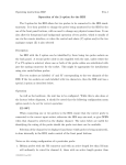
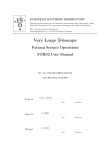
October 2013. Figure 1 shows KOSMOS mounted in the Cassegrain Cage of the 4-m
Mayall telescope.
Figure 1: KOSMOS mounted in the Cassegrain Cage of the 4-m Mayall
telescope.
KOSMOS was built by a partnership between Ohio State and NOAO, and is largely based
on the OSMOS (Ohio State Multi-Object Spectrograph) instrument at the MDM 2.4m
Hiltner telescope. The heritage from OSMOS includes an all-refractive optical design
that enables imaging, longslit, and multi-slit spectroscopy over a wide field, rapid
Page 4 of 45
C/KOSMOS Operations Manual V1.3
reconfiguration between observing modes, and the capability to have a wide range of
slits, filters, and dispersers mounted simultaneously.
KOSMOS has a nearly identical twin named COSMOS (Cerro Tololo Ohio State MultiObject Spectrograph) at the 4-m Blanco Telescope of the Cerro Tololo Inter-American
Observatory. Except where noted otherwise explicitly, all contents of this manual apply
to both instruments, even if only KOSMOS is named.
This manual is intended to describe operational tasks required to support the
instrument; its target audience is therefore the NOAO scientific/mountain support staff,
rather than the outside user. Support staff should also become familiar with the User
Manual, as this provides a more complete description of the instrument and how it is
used while observing.
Page 5 of 45
C/KOSMOS Operations Manual V1.3
2 Safety
This section summarizes safety hazards associated with KOSMOS and COSMOS, and
describes the procedures and design modifications that have been adopted to reduce or
mitigate these hazards. Unless indicated otherwise, all descriptions of hazards and
mitigations apply to both instruments.
The tables below contain a column identifying the hazard, a column describing the
hazard in detail, and a column describing the mitigation for that hazard. The first table
comprises hazards posing a risk to personnel; these hazards may also pose a risk to
equipment. The second table lists hazards that only pose a risk to equipment.
For some hazards, safety labels are provided as part of the mitigation. Subsequent
sections in this manual will provide documentation on associated handling procedures;
this document will be included as part of such manuals. In addition, mountain staff will
be trained regarding instrument safety as part of the commissioning and acceptance of
the instrument at each observatory site. This document is not intended as a substitute
for training, and any potentially hazardous procedures should not be carried out by untrained personnel.
General observatory safety procedures are not covered in this document, but should be
followed at all times. These include use of safety harnesses while installing equipment
using the mirror lift.
Note: this section of the manual replaces the “KOSMOS/COSMOS Safety Document”,
which was last revised March 13, 2014.
Note: the list of labels should be cross-checked against the individual instruments and
implemented where any are missing.
Page 6 of 45
C/KOSMOS Operations Manual V1.3
Personnel Hazards
Hazard
Name
Hazard Description
Hazard Reduction/Mitigation
Instrument
Weight
The instrument plus
adapter have a
combined weight of
~600 lb.
1) A suitable handling cart is provided,
which includes provisions for
installation/removal on the telescope
2) Installation and removal procedures
will be documented; these are (by
design) very similar to those for
existing NOAO instruments.
3) Procedures for instrument
disassembly will be documented.
However, disassembly is expected to
occur infrequently (less than
once/year).
Tip Hazard on
Cart
The instrument must
be located on the cart
at a height suitable for
installation on the
telescope and for
servicing, which raises
the center of gravity.
The cart design includes a steel
baseplate intended to ensure that the
cart will not tip over even if tilted 30
degrees [exact tilt TBC]. The cart
caster locations have been moved to
increase “footprint”. Cart casters are
spring-mounted and appropriately
sized.
Page 7 of 45
C/KOSMOS Operations Manual V1.3
Hazard
Name
Hazard Description
Hazard Reduction/Mitigation
Rotation
Hazards on
Cart
1) The instrument is
mounted on the cart
so it can be manually
rotated from vertical to
horizontal on the cart
with the telescope
adapter removed.
1) Provide safety labels for telescope
adapter and locking pins (plungers) on
cart.
2) Require 2 people to be involved
when the instrument is rotated on the
cart, unless the rotation moment has
been verified to be acceptably small
However, attaching the (normally the case when electronics+
telescope adapter
dewar are installed; otherwise this
creates a moment that precaution is necessary)
does not allow safe
manual rotation.
2) The rotation of the
instrument, even
without the adapter,
should be restrained
manually until the
locking pins are
engaged
Sharp corners
Adapter
Weight
In the cage, it is
possible to hit one’s
head on sharp edges
or corners of the
instrument
1) Primary access to the instrument for
changing masks, filters, etc. is through
the side facing the cage door in the
default rotator position.
2) The instrument design does not
include corners likely to interfere with
normal servicing. However, the
instrument access will be reviewed
after installation and padding can be
added if required.
The adapter must be
Safety label for telescope adapter, plus
removed for major
documentation of handling procedure
service, and requires
(including lift points).
lifting equipment due
to its weight (~130 lb).
Page 8 of 45
C/KOSMOS Operations Manual V1.3
Hazard
Name
Hazard Description
Hazard Reduction/Mitigation
Cryogen
Hazards
The detector dewars
use liquid nitrogen.
Cryogen burns are
possible; suffocation is
possible but unlikely in
the dome environment.
1) The dewars are standard
observatory dewars, for which
appropriate cryogen safety procedures
have been established. KOSMOS and
COSMOS will follow the standard
procedures.
2) A fill tube extender will be attached
to the dewar to provide better access
(e.g, at the side of the instrument or
near the cage door)
Electrical
Hazards
The instrument
electronics box
contains standard AC
line voltage.
The hazardous voltages are only
exposed by removing covers. Safety
labels will be provided. The electronics
box can be disconnected from power if
required.
Slew Hazard
The user software can
request telescope
motions; large motions
(slews) can be
hazardous if executed
unexpectedly
In practice large motions never occur;
if requested they will not be performed
as slews (high speed)
Trip Hazard
Cables between
connectors on the cage
wall and the
instrument can pose a
trip hazard if not
secured properly;
tripping may damage
the cables as well as
injure people
Cables should run across floor of cage
under a cable protector (Mayall), or in
troughs under the floor (Blanco).
However, the cables must be secured
with enough slack to permit operation
of the rotator throughout its range.
Rotation should be verified at the time
of initial instrument installation.
Equipment Hazards
Page 9 of 45
C/KOSMOS Operations Manual V1.3
Hazard
Name
Hazard Description
Hazard Reduction/Mitigation
Collision
Hazard on
Cart
Electronics boxes on
the outside of the
instrument could be
damaged if the cart
collides with walls or
door frames.
The cart base has been enlarged to
define a “footprint” larger than the
instrument.
Electrical
Hazard to
Detectors
Removal of detector
controller from dewar
creates a static hazard
to the CCD
Safety label and training. Mountain
staff have extensive training already
regarding static hazards for CCDs.
Hazard from
Moving
Mechanisms
The mechanisms inside
the instrument might
move while a person is
working on them. The
motors driving the
mechanisms do not
have enough power to
cause injury, and will
stall. There might be
contact with optical
surfaces, however,
which is not desirable.
1) Mechanisms cannot be accessed
without removing access covers.
2) Motor motions can be prevented by
disconnecting either the power cable or
the Ethernet cable to the instrument
electronics (preferred solution for daytime servicing). Alternatively, a second
person can be stationed at the
instrument’s computer console
(preferred solution for night-time
access).
3) All mechanism access, such as for
filter or mask exchange, will be
performed by trained observatory
personnel (not by observers).
Page 10 of 45
C/KOSMOS Operations Manual V1.3
Hazard
Name
Hazard Description
Hazard Reduction/Mitigation
Optics
Hazards Exposure
1) The instrument
entrance port is “uplooking” and dirt,
water and small
objects can enter and
contaminate or
damage optics
1) There is a “dark slide” at the front of
the instrument that should be closed
when the instrument is not in use (i.e.,
during the day or when not installed on
the telescope). The cover can be
accessed for debris removal through
the guider when the instrument is on
the telescope.
2) The instrument rear
port is open when the
dewar is removed, and
dirt, water and small
objects can enter and
contaminate or
damage optics
2) There is a cover for the rear of the
instrument that should be installed
when no dewar is installed. The cover
attaches to the side of the instrument
when not installed, so it will not get
lost.
3) There will be labels for the dark
slide and the rear cover.
4) The covers and electronics boxes
are not necessarily fully hermetic, and
water can occasionally drip in the
coudé lab storage area, so a cover for
the instrument will also be provided,
for use when off the telescope. This
will provide additional dust protection.
Optics
Hazards Handling
The instrument is
designed to allow slit
masks, filters, and
dispersers to be
exchanged, but they
can be damaged if
they are mishandled,
and may also damage
other optics elements
if dropped on them.
1) All exchanges will be performed by
trained observatory personnel.
2) All optics will be installed in their
cells prior to the exchange; the cells
are designed with captive screws
through access covers.
3) Disperser exchanges are scheduled
in advance and performed only during
the day-time.
Page 11 of 45
C/KOSMOS Operations Manual V1.3
Hazard
Name
Hazard Description
Hazard Reduction/Mitigation
Dewar
Installation
Hazard
The clearance between
the rear of the
spectrograph camera
and the front of the
dewar is only ~4 mm.
There is thus potential
for damaging the
dewar window or the
rear lens of the camera
during installation.
1) Final element of camera is slightly
recessed inside camera barrel. Dewar
window is recessed inside faceplate. 2)
The dewar assembly will be aligned to
rear of instrument using alignment pin
and installation jack; this allows careful
and repeatable installation. 3) Dewar
installation is scheduled in advance,
performed only during the day-time,
and only by trained observatory
personnel.
CCD Exposure The LBNL CCD can be
to Light
damaged by exposure
to high light levels
when powered on.
The constraints imposed by this hazard
are not yet well-defined, but it appears
probable that there is no astronomical
observation that will damage the CCD.
Appropriate procedures will be
established once the hazard is
quantified, which are likely to require
either powering down the CCD or
implementation of a special erase
mode while the instrument is being
serviced (including filter and slit mask
changes). This hazard applies only to
the LBNL CCD; there is no such hazard
associated with the e2v CCD.
Cass Rotation
Hazard Cables
Until the cable wrap-up is modified, all
rotations greater than 1 degree will be
done at zenith. This restriction does
not apply to CTIO.
The KPNO cassegrain
rotator cannot safely
rotate over large
angles (many degrees)
when the telescope is
not at zenith, due to
the design of the
rotator cable wrap-up.
Page 12 of 45
C/KOSMOS Operations Manual V1.3
Hazard
Name
Hazard Description
Hazard Reduction/Mitigation
Cass Rotation
Hazard Drives
The cassegrain
rotators on both
telescope may suffer
drive damage if the
moment around the
rotation axis is too
large.
Provide appropriate ballast weight for
the instrument to ensure rotation
moment is within specifications [<150
ft-lb; weight design balances to 50 ftlb].
Page 13 of 45
C/KOSMOS Operations Manual V1.3
3 C/KOSMOS Installation and Removal
This section covers the installation of the instrument on the telescope, its removal, and
the installation of the CCD dewars on the instrument. This section, as well as sections
4-6, includes material from two prior documents: the “KOSMOS Installation and
Removal” document, last revised March 13, 2014, and the “Dewar Installation and
Operation Document”, last revised April 1, 2014.
3.1 C/KOSMOS Installation
This section describes the detailed procedures for installing and removing KOSMOS and
COSMOS from the 4-m telescopes. Unless explicitly stated otherwise “KOSMOS” refers
to both instruments and the procedures are the same for both telescopes.
All procedures described below should be carried out by 2 people, except for cabling
and wiring. For some procedures an additional person may be helpful but is not
essential.
For reference, keep in mind the following weights:
KOSMOS Weights
Component
Weight, lb (kg)
KOSMOS instrument, with electronics and
counterweight
530 lb (240 kg)
KOSMOS telescope adapter
145 lb (66 kg)
KOSMOS cart
445 lb (202 kg)
3.1.1 P reparation for I nstallation
KOSMOS is installed on the telescope while oriented vertically on its handling cart, with
the telescope adapter attached. It will normally be stored in this configuration, with a
water-resistant cover over the instrument.
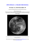
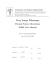
The figure below shows the instrument, with several components that are referenced in
the text appropriately labelled.
Page 14 of 45
C/KOSMOS Operations Manual V1.3
Telescope adapter
Instrument
(pivot point)
Locking pins
cradle
Instrument cart
CCD dewar
Figure 2: KOSMOS on handling cart, on mirror lift with dewar installed. This is
the normal orientation for storage, and the required orientation for installation.
Several elements referenced in the text are labelled. This view is from the side
opposite the access hatches. The CCD dewar shown is a KPNO dewar used on
KOSMOS; the CTIO dewars (SOI style) for COSMOS are larger and colored black.
Note – for extended laboratory testing, the telescope adapter may have been removed,
and the instrument then rotated to the horizontal position. See steps below if this is the
case.
Page 15 of 45
C/KOSMOS Operations Manual V1.3
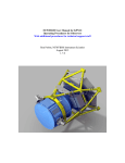
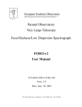
Figure 3: COSMOS on handling cart; note the different dewar design. This
figure shows the instrument in the horizontal position with the adapter plate
removed.
Assuming the instrument is in the vertical storage position, it is prepared for installation
by removing the cover and performing a visual inspection of the mounting surface and
area around the dark slide (see last step, below).
The CCD dewar may be left installed on the instrument while it is stored, in which case
it can be left on the instrument for installation on the telescope. If not, it should be
installed on the instrument after the instrument is installed on the telescope, as
described below. It is recommended that the dewar be cooled down prior to
installation, following standard procedures for KPNO or CTIO CCD dewars (see section
4, below). This should be done whether the dewar is installed on the instrument
beforehand, or subsequently.
If the instrument is oriented horizontally, it should be rotated to the vertical position. If
the telescope adapter is attached (which is unlikely), it must be removed in order to
rotate the instrument safely, because the instrument is in or near balance only with the
adapter removed. It is not recommended to store the instrument in the horizontal
position, because the cover won’t fit, and therefore it is unlikely to be horizontal unless
it has just undergone maintenance.
Removal of adapter (if required). Two straps should be attached to 4 eyebolts that in
turn are fastened to the adapter using holes in the outer bolt circle at approximately 90degree intervals, with one strap on the upper pair and one on the lower pair. A hoist is
Page 16 of 45
C/KOSMOS Operations Manual V1.3
used to take up the weight of the adapter using the upper strap. (The lower strap is not
required for removal, so if the adapter will not be re-installed immediately, it can be
omitted.) The bolts attaching the adapter to the instrument are then removed. These
are accessed through the top plate (surface attaching to the telescope) of the adapter.
Once the adapter is removed, it can be lowered to the ground. Note – alternative
arrangements are acceptable, provided the adapter’s orientation is properly
constrained.
Rotation of instrument (if required). The 2 locking spring-pins on the carts that retain
the instrument in the horizontal position are retracted and turned to lock them in the
“out” position. The instrument is then rotated to vertical by one person while the
second person rotates and inserts the spring pins for the vertical position.
Note that, while horizontal, the instrument rests on a cross-bar and will not rotate
spontaneously when the locking pins are removed. This is not the case when the
instrument is vertical and the instrument must be manually restrained until the locking
pins are inserted. The instrument imbalance is small, so lifting equipment is not
required for this purpose. The CCD dewar can be installed before rotating to the vertical
position, although this is not required.
Installation of adapter (if required). Prior to attaching the adapter, inspect the surface
of the instrument front plate and the area around the dark slide and make sure they are
clean – wipe them off if necessary.
For purposes of installation on the telescope the adapter should be installed when the
instrument is vertical. This requires the same arrangement of eyebolts and straps used
for installation, except that the adapter is lifted using both straps, so it remains
horizontal. The adapter is then aligned with the top of the instrument, and bolts are
inserted through the top and partially threaded. The hoist is then lowered so the
adapter weight is fully borne by the instrument and the bolts are tightened. Remove the
straps and eyebolts.
The height of the instrument on the cart is such that it may be helpful to use a small
stepladder or stool when fastening the adapter.
Inspection. If a visual inspection was not already performed (see preceding step), check
the mounting surface of the adapter and the area around the instrument dark slide;
clean is necessary.
3.1.2 I nstallation on Telescope
KOSMOS is installed on the telescope using the regular cage bottom. It may be possible
to use the NEWFIRM cage bottom on the Blanco, for COSMOS, but on the Mayall it is
not possible to add enough weight to the NEWFIRM cage bottom, and it should not be
used. At present, the original cage bottom is used on both telescopes.
Page 17 of 45
C/KOSMOS Operations Manual V1.3
Remove the cass cage bottom and whatever instrument is installed on the telescope,
using the mirror lift and following standard observatory procedures for those two items.
Lower the lift and move the instrument that was removed into its customary storage
location.
If the rotator guider assembly was not in use, it should be installed at this point
following standard observatory procedures. The rotator should be oriented to
position angle 90 (approximately) for Mayall installation, and to position
angle 270 for Blanco installation.
KOSMOS installation on rotator guider:
•
•
•
•
•
•
•
•
Move KOSMOS onto the mirror lift.
Rotate KOSMOS on its cart so the access covers on the instrument are facing the
location of the cage door. In this orientation, the electronics box will be on the
right as you enter the cage. Note – this applies to both telescopes, however the
access covers are facing South on the Mayall and North on the Blanco, which is
why the rotator angles specified above differ by 180 degrees.
Raise the lift until the locating pins on the bottom on the rotator guider engage
the notches in the telescope adapter on top of the instrument. The top of the
adapter does not need to be in contact with the underside of the rotator. There
is some travel in the spring casters, but it is important not to raise the lift too far,
as this could damage the handling cart or the instrument enclosure if the
allowable travel is exceeded.
Insert and partially thread the mounting bolts.
IMPORTANT! Retract and lock the spring pins on the cart in the retracted
position. Failure to do this will damage the pins and may damage the instrument
and/or cart when the lift is lowered.
Tighten the mounting bolts.
The mirror lift can now be lowered; the cart will drop away from the instrument
and can be moved out of the way.
The “cradle” (interface between cart and spectrograph enclosure) could be
removed at this point. We recommend leaving it installed, however, as it does
not get in the way.
Page 18 of 45
C/KOSMOS Operations Manual V1.3
Figure 4: KOSMOS on handling cart, on mirror lift while being installed on the
rotator. The view is from the direction of the cage door; note the access hatches
visible from this position.
Page 19 of 45
C/KOSMOS Operations Manual V1.3
Figure 5: View from below of KOSMOS after installation. The cradle has been
left attached to the instrument. Note safety harnesses attached to the mirror cell
bottom (top left, lower right).
Now move the cage bottom onto the lift, raise the lift, and attach the cage bottom
according to standard procedures.
Note: The cage bottom can be attached either after or before installing the CCD dewar
and completing cable connections; at present it appears to be preferable to install the
dewar itself first, but complete any cabling steps after installing the cage bottom.
Once installation of the instrument is complete, the mirror lift should be lowered and
the cart and instrument cover should be stored.
Dewar alignment. This procedure is not required if the dewar adapter ring has been left
attached to the dewar. However, it does no harm to verify alignment if there is any
doubt. The critical parameter for dewar alignment is rotation, where the slit should be
aligned parallel to the short axis of the CCD (which may be either rows or columns,
depending on the CCD used). See section 6 for details of this procedure.
Page 20 of 45
C/KOSMOS Operations Manual V1.3
3.2 Instrument Removal
The procedure for instrument removal is the reverse of that for installation. It is not
necessary to remove the CCD dewar, but it may be desirable to do so if the instrument
will not be used for a long time and the dewar needs to be kept cold or requires
maintenance.
•
•
•
•
•
•
•
•
•
•
Disconnect the power, ground and Ethernet cables for the CCD dewar and
spectrograph
Bring the handling cart up on the mirror lift. If the dewar is to be removed, also
bring the lab cart and dewar installation fixture.
Remove the cage bottom, lower the lift and set the cage bottom aside.
If the dewar is to be removed, do so at this point following the procedure
outlined above.
If the “cradle” for the instrument was removed during installation, attach it to
the instrument at this point. Note – normally it would be left in place.
Bring the mirror lift up so the cart is close to or touching the instrument. As with
installation, do not bring the lift up so far that the travel of the cart casters is
exceeded. Make sure all locking pins are retracted. Caution: the forks have
limited clearance around the instrument; make sure they clear the instrument
and do not catch or pinch any cables. It may be necessary to remove cables or
cable ties beforehand.
Loosen the bolts attaching the instrument to the rotator/guider, until the
instrument is resting on the cart.
Engage the locking pins on the cart that hold the instrument in the vertical
position.
Remove the bolts that attach the instrument to the rotator guider.
Lower the mirror lift, take the instrument on its handling cart to the storage area,
and cover it.
You can now install another instrument, or just the cage bottom.
3.3 Dewar and Controller Installation
This section describes the preparation and installation of the COSMOS dewar on the
spectrograph. Section 4 describes basic operation of the Torrent controller, Section 5
reviews basic cryogen fill procedures. The alignment interface is described in Section 6.
The controller operation on COSMOS is identical with operation on KOSMOS; other
procedures differ to some extent.
Page 21 of 45
C/KOSMOS Operations Manual V1.3
3.3.1 Dew ar P reparation
Prior to installing the instrument on the telescope, the dewar should be pumped down
and cooled. When, in future, there is more than one dewar available, dewars should be
pumped and cooled before being installed on the telescope.
If the dewar was recently pumped (within a month or so), pumping may be omitted,
but if time permits it's always preferable to start with an optimal vacuum. The dewar
can be cooled after installation on the telescope, if necessary.
The steps are summarized below; staff performing these steps are assumed to be
familiar with vacuum/cryogenic procedures. Anyone without such training should seek
further instruction first.
• Dewar pumping should be done with a quality turbo pump or similar device. The
dewar should be warm when pumped. Generally, the measured pressure should
be in the few mTorr range or less after a few hours; at this point the dewar's
vacuum valve should be closed and the pump can be turned off. The pump can
be run longer (e.g., overnight or over a weekend), but there is little advantage
to doing so.
• The dewar should be filled (see section 5). Because the initial fill has to cool the
nitrogen tank, detector mount, and other hardware, you should re-fill after ~2-6
hours to ensure it holds for the expected amount of time. Do not fill the dewar
while the vacuum pump is pumping it.
3.3.2 Dew ar I nstallation
When the dewar is not installed on the spectrograph, a cover plate is installed over the
opening. There is also a cap that is installed on the rear of the camera (Figure 6). Do
not forget to remove this cap before installing the dewar (Figure 7)!
Page 22 of 45
C/KOSMOS Operations Manual V1.3
Figure 6: View through rear of spectrograph showing end cap on camera.
Figure 7: View with end cap removed.
Page 23 of 45
C/KOSMOS Operations Manual V1.3
The procedure for KOSMOS is similar, however the opening for the dewar adapter is
smaller.
The dewar adapter (see Figure 8) is attached first to the dewar.
Alignment tongue
Note controller location
Cap screw
Detector long axis
Figure 8: COSMOS dewar adapter attached to dewar, viewed from above. The
tongue that is used for precision alignment goes at the bottom when installed
(shown at the top here), and the dewar is installed so that the Torrent controller
is on the right side when looking at the spectrograph from behind the dewar.
Note the cap screw in the adapter covering the hole in front of the controller.
Figure 9 shows the COSMOS dewar adapter installed without the dewar, in order to
show the interface better. The basic concept is that the adapter is permanently bolted
to the dewar; when it is installed, the central boss fits into the hole in the back of the
instrument (see Figure 7). The adapter plate allows for a limited amount of rotational
adjustment (see Figure 9); once the rotation is determined the pin shown in Figure 4 is
bolted down. Thereafter, the dewar can be removed and re-installed without losing
rotational adjustment. (See Section 6 for details on dewar alignment.)
Page 24 of 45
C/KOSMOS Operations Manual V1.3
Slotted holes attach
adapter to
instrument while
allowing rotational
adjustment
Slotted plate and
alignment pin define
rotation position
when bolted down
to adapter
Figure 9: COSMOS dewar interface installed on spectrograph, without dewar, to
illustrate installation features.
The equivalent features for KOSMOS are shown below (see also Figure 13).
Reference these figures when reading the rotational alignment procedures in
Section 6.
Page 25 of 45
C/KOSMOS Operations Manual V1.3
One of four holes for
alignment pin
Bolts attach dewar &
adapter to instrument
Bolts with slotted hole for
rotational adjustment (2
on each side of dewar).
Micrometer barely visible
on left of dewar; see
next figure
Figure 10: KOSMOS dewar installed on spectrograph, with installation and
alignment features indicated
Figure 11: KOSMOS dewar rotation adjustment micrometer. The micrometer for
COSMOS is essentially the same.
Page 26 of 45
C/KOSMOS Operations Manual V1.3
3.3.3 Electrical Connections and R elated
Once the dewar is installed, several electrical connections must be made (see Figure
10). These are:
•
Power for the controller (via the laptop power supply); connect to clean power
•
Power for the controller fan; connect to clean power
•
Fiber connection to "pan" computer
•
Ground connection, between Torrent, dewar, and power strip 3rd pin
•
Shutter control cable, from side of Torrent to input on instrument electronics box
(IEB) on the side of the instrument
•
In addition, connect the dry air hose to the barbed connector near the dewar
faceplate; connect the other end of the hose to the dry air outlet in the cage.
Make sure dry air is flowing! This step is not required when the instrument is
being operated in a laboratory environment.
•
Power cord to the IEB should be connected to clean power.
•
Important: run the cables across the slanted surface of the cage under a cable
protector, which should then be taped in place using cable tape (Mayall) or in the
troughs in the cage bottom (Blanco). This reduces trip hazards. Make sure there
is enough slack directly beneath the instrument to allow it to rotate through the
full range of the rotator.
Page 27 of 45
C/KOSMOS Operations Manual V1.3
Controller
power
Fiber link
Power switch
button
Fan power
Ground
connection
Figure 12: Torrent controller connections. The fiber cable is the orange pair
connected at the top of the box; the power connection is to its left and the
ground connection just below that. Note the ground cable is also connected to
the dewar body at the vacuum gauge (lower left). The fan power cable connects
to the fan at its top in this view. The shutter connector is on the underside of the
controller. The shutter cable connection is underneath the controller in the view;
it is shown better in Figure 14. These connections are the same for both
instruments.
Page 28 of 45
C/KOSMOS Operations Manual V1.3
Figure 13: View from below of KOSMOS CCD dewar after installation. Note that
the cage bottom, when installed, is only a few inches below the fill fixture. The
Torrent box (attached to dewar, on right) has the ground, fiber, and fan power
cables already connected. Note the dry air hose at the fitting on the dewar
adapter.
3.3.4 Dew ar I nstallation in Cage
The KOSMOS dewar can be installed after the instrument has been installed on the
telescope; procedures for doing this for COSMOS have not been developed yet. The
procedure is as follows:
•
There should be a cover in place over the exit port on the spectrograph. Remove
it and attach it to the side of the instrument. There may also be a cap over the
back of the spectrograph camera; this must be removed as well.
•
The dewar will normally be stored with its adapter ring attached. If the adapter
ring is not attached, attach it to the front of the dewar. Note that this means the
dewar must be re-aligned rotationally after installation (see below).
Page 29 of 45
C/KOSMOS Operations Manual V1.3
•
The dewar should preferably already be cold at the time of installation, but it can
be cooled after installation; this is recommended only when the instrument is
installed well before any use on the telescope.
•
If the dewar is being installed without the cage bottom in place:
o The dewar installation fixture should be placed on a lab cart and the
dewar should be clamped into it, facing up. The jack on the installation
fixture should be lowered.
o The mirror lift is then used to raise the dewar until it is close to the
bottom of the instrument. “Close” means within the range of travel of the
jack on the installation fixture. Do not try to use the mirror lift to engage
the alignment pin on the back of the instrument, as it does not have the
required fine motion capability, and you may seriously damage the dewar
or the spectrograph optics.
•
If the dewar is being installed with the cage bottom in place, lower the jack on
the the installation fixture, clamp the dewar in place, and slide the fixture under
the instrument
•
Carefully use the jack on the installation fixture to raise the dewar while guiding
it onto the dowel pin. Check before doing this that the hole in the dewar adapter
ring matches up with this dowel pin on the back of the instrument. When the
front of the dewar is nearly flush with the back of the instrument, this pin will
accurately define dewar rotation about the optical axis.
•
Install and tighten bolts through the adapter ring in the back of the instrument.
•
Attach the fill tube extender to the dewar fill tube and the side of the instrument.
3.3.5 Dew ar R em oval and Exchange
KOSMOS (and COSMOS) will eventually have 2 available dewars, which can be
exchanged when the instrument is mounted on the telescope. The exchange can be
carried out while the cage bottom is installed, as described above.
Dewar removal. The process is essentially the reverse of installation.
•
Remove the fill tube extender and disconnect the power, ground and fiber
cables. Remove the dry air hose.
•
Lower the jack in the installation fixture, and slide it under the dewar, then raise
the jack
•
Loosen and remove the mounting bolts on the dewar adapter ring.
•
Clamp the dewar to the installation fixture
Page 30 of 45
C/KOSMOS Operations Manual V1.3
•
Lower the jack in the installation fixture until the dewar is clear of the
instrument.
•
Slide the installation fixture out from under the instrument
•
Unclamp and remove the dewar.
The second dewar can now be installed following the procedures outlined under
instrument installation.
Page 31 of 45
C/KOSMOS Operations Manual V1.3
4 Controller Operation
4.1 Basic Operation
The controller is normally in one of three states: off, on but not connected, and
connected. When the controller is on, whether connected or not, pushing the power
button briefly (see Figure 14, below) will cause it to light up green. If on but not
connected, the ethernet connectors (to the right of the fiber connector in Figures 12
and 14) will glow orange (the controller is in this state in Figure 12).
Figure 14: Location of power button. Note that the Ethernet connectors are not
lit up (compare with Figure 12) – this means that the controller is off, or is on
and connected.
In order to start up the controller, the following steps are required:
•
Make sure the software is stopped. In the xterm window for the NOCS, type:
nocs stop all
nocs stop hardware
•
(For more details, see the relevant section of the User Manual)
Now start the controller by pushing and holding the power button for a second
or two. The ethernet connectors will glow orange. If the shutter is connected and
the instrument electronics are on, the shutter will cycle.
Page 32 of 45
C/KOSMOS Operations Manual V1.3
•
Now start the NOCS (see the User Manual for additional details) by typing in the
xterm:
nocs start hardware
nocs start all
Wait for all the windows to display. Once the detector control window (NMSL)
displays, the lights on the ethernet connectors should turn off. The text at the
top of the NMSL window may sometime show error messages regarding incorrect
voltages; these can usually by fixed by typing
nmslReset
•
in the xterm.
Verify that everything is working by taking an image (a bias or "zero" frame is
easiest, see the User Manual for details).
4.2 Troubleshooting - Controller Not Working
When the instrument is first installed, it is a good idea to re-start everything, including
the computer racks. The command to use is:
nocs reboot rack
from the xterm connected to the KOSMOS (or COSMOS) rack. Note that this action will
close the connection, so you will need to re-connect once the re-boot is complete. This
step can be omitted if the instrument has been running without problems in the lab
immediately before installation, but should be kept in mind if all else fails.
More generally, if there are problems getting the detector controller to operate properly
(either error messages, or operation in simulation mode [NMSL text window shows
orange background, not white]), a careful and complete shutdown and restart is
recommended (but read the notes at the end of this section first):
1. Issue NOCS commands:
nocs stop all
nocs stop hardware
2. Turn off Torrent controller (see above, make sure shutter activates when doing
this)
3. Turn off IEB (instrument electronics)
4. Disconnect power from the Torrent for 30 seconds (controller power, don't mix
this up with the fan power, which is separate)
5. Reconnect power to Torrent
6. Turn on IEB; wait 10 seconds or so
7. Turn on Torrent controller (see above, make sure shutter activates and LEDs in
Ethernet connectors on Torrent illuminate)
Page 33 of 45
C/KOSMOS Operations Manual V1.3
8. Issue NOCS commands
nocs start hardware
nocs start all
A shortcut procedure that will solve most connection problems is to follow the sequence
above, but skipping steps 3-7. In this case, wait ~30 seconds after powering the
Torrent controller off before re-starting it. If the shutter is not activating, or the LEDs
on the Ethernet connectors do not illuminate, you should execute the full procedure.
Note - if you think it may be necessary to reboot the rack computers, do so after step
4; since the reboot takes more than 30 seconds (several minutes), you can proceed to
step 5 as soon as the racks come alive and you have connected to them again.
Note - when you install the instrument, you should consider that you are at step 4 in
the procedure above, and continue accordingly.
Note - there are also circumstances where the fiber link between the Torrent and the
computer rack should be reset. Try this before re-booting the rack.
4.3 Troubleshooting - Noise
If everything appears to be working, but there is excess noise in the bias ("zero")
images, there is undoubtedly a grounding issue. The noise will manifest itself as a
pattern on the raw images.
• If the noise is very high, there is most likely a missing connection - check that
the connections have all been made (see figures above for the COSMOS and
KOSMOS dewars, which are not identical).
• If the noise is somewhat higher than expected (i.e., above 10 ADU standard
deviation), you can try moving the location where the ground plug is plugged in
to a cage power socket. This may or may not help. There isn't a location that is
guaranteed to reduce noise below 10 ADU, for either instrument. (At least not
right now.)
Page 34 of 45
C/KOSMOS Operations Manual V1.3
5 Dewar Filling
The COSMOS dewar has a hold time of 40 hours or longer; it is recommended that it be
filled daily, but the exact time of day is obviously not critical.
The fill tube attaches as shown in Figure 15 - do not overtighten the fitting onto the
dewar neck! Use two wrenches if needed to tighten the additional fittings. The fill tube
will be somewhat loose; this is OK. Put a piece of dense foam or cardboard underneath
the fill tube when filling from the side, in order to protect the vacuum gauge and valve.
If you are filling on the telescope, the dewar is vertical and the foam or cardboard is
not necessary. If you are filling on the telescope, you will also need a fitting with bend
in it because there is not enough space between the dewar and the cage bottom for a
straight fitting. See Figure 13 for a view of KOSMOS with such a bent fitting attached.
Figure 15: Fill fitting and nitrogen line attached to dewar.
Once you have attached the fill tube, open the valve to the storage dewar slightly.
Liquid nitrogen will cool the line initially, and will then start flowing into the dewar.
Some dripping from the fill fixture is normal at this point. You can open the valve to the
storage dewar more fully at this point. Once the dewar is full (typically about a couple
of minutes), liquid will start to spill out of the holes in the side of the fitting. Close the
valve.
Page 35 of 45
C/KOSMOS Operations Manual V1.3
If you are in the lab, or have time, you can wait for the fitting to warm up and remove
it by hand. Otherwise you will need wrenches to do so - always use two wrenches for
this, in order to protect the dewar neck. For lab work, it is not necessary to remove the
nitrogen line.
The procedure for KOSMOS is generally similar (see Figure 13 for a view of the fill
fitting). However, the hold time is substantially less than for COSMOS - about 15 hours.
Therefore the dewar must be filled twice a day, generally at the start of the night and
at the end of the night.
Page 36 of 45
C/KOSMOS Operations Manual V1.3
6 Dewar Alignment
The dewar rotation should be adjusted using the following procedure:
1. Loosen the screws holding the dewar to the back of the spectrograph, the
screws holding the alignment pin plate to the adapter, and the micrometer and
screw that engage the alignment tongue (see Figures 8 and 9).
Slotted attachment
point
Alignment pin & plate
Alignment feature;
attachment point
Shutter
cable
Figure 16: View of COSMOS mounted on instrument showing the micrometer
and screw engaging the alignment feature, the alignment pin plate, and one of
the slotted attachment points. The shutter cable is also shown installed on the
controller, at right. See Figures 10 and 11 for KOSMOS equivalent features.
Page 37 of 45
C/KOSMOS Operations Manual V1.3
Figure 17: View of COSMOS dewar showing additional slotted attachment points.
There are a total of 5. See Figure 10 for KOSMOS features; it has 4 bolts that must
be loosened for rotational adjustment
2. Take an image through the spectrograph with one of the long slits in position,
but without a disperser. This produces a single image of the slit, regardless of
light source. If a disperser is used, an arc lamp is required and the lines will be
curved.
3. Compare the “Y” positions of the 2 ends of the slit; unless they are within ~1
pixel you will likely want to make an adjustment.
4. Tighten the micrometer against the adjustment tongue and rotate a couple of
turns of the micrometer.
5. Repeat the measurement (2) and see how the ends of the slit have moved.
a. If the rotation is in the desired direction, continue turning the micrometer
and repeating the measurement. One turn of the micrometer is (very
roughly) a couple of pixels difference end-to-end on the slit.
b. If the rotation is in the wrong direction (or if you over-shoot), back off the
micrometer by the desired amount, then tighten the opposing screw until
the tongue is touching the micrometer end. Don’t over-tighten.
6. You should be able to get the end-to-end difference smaller than a pixel.
7. Once you are satisfied, tighten the attachment screws and the alignment pin
plate, then take one last image to verify that nothing has shifted.
Page 38 of 45
C/KOSMOS Operations Manual V1.3
7 Filter and Mask Changes
Filter changes are normally performed only during the day; mask changes can be
carried out at night (by the telescope operator, but the observer may be able to help).
Filters or multislit masks should be installed in holders. Longslits are pre-assembled into
holders, so it's a matter of selecting the longslits to be installed.
Filters are installed in holders by the day crew; since there are spare filter holders, any
filters you may have requested should be already installed in holders. At the Mayall,
they will be kept in the loading room (old plate loading room outside the control room).
Access to the instrument for this purpose is shown in the figures below:
Figure 18: Location of access ports for slits (top) and filters (bottom).
Page 39 of 45
C/KOSMOS Operations Manual V1.3
7.1 Installing Multislit Masks in Holders
To install masks, you need a vacant mask holder and a 1.5 mm [TBC] Allen key or
driver. Use the driver to loosen and rotate the clamps holding the retaining ring in the
holder, and carefully remove the ring (see Figure 19, below).
Figure 19: Mask holder with retaining ring removed (top). The 4 clamps can be
seen around the inner edge of the holder. Alignment pins can also be seen at
approximately the 6, 11, and 12 o'clock positions. A close-up is shown (bottom)
where you can see the clamps and alignment pins.
Page 40 of 45
C/KOSMOS Operations Manual V1.3
The KOSMOS masks are cut from stainless steel shim stock that is coated black
on one side. One such mask is shown in Figure 20, below.
COSMOS masks are cut either from aluminum shim stock that is blackened on
both sides, or a thin carbon fiber sheet. The general appearance for the COSMOS
masks will be similar to those for KOSMOS, except that neither side will be shiny.
The black side of the KOSMOS masks faces the collimator, to reduce ghost
images. While both sides of the COSMOS masks are black, the alignment pins in
the mask holders ensure that the orientation is always correct.
Figure 20: Typical multislit mask.
The mask should be inserted in the holder, making sure to align the holes in the
edge of the mask with the alignment pins. If this is done correctly, the shiny side
should be down for correct alignment. (For COSMOS masks, where there is no
shiny side, there is still only one way the pins and holes will line up.) Now install
the retaining ring over the mask and alignment pins, and then tighten the clamps
to hold the ring in place. The clamps may need a little assistance to rotate to the
correct position. If correctly assembled, the mask in its holder should look like
Figure 21.
The black side of the mask is facing the detector, not the telescope secondary,
when installed in the instrument. This is to minimize ghost images on the
detector.
Page 41 of 45
C/KOSMOS Operations Manual V1.3
Figure 21: Mask installed in holder. Note black side facing up.
7.2 Installing Filters and Slits into KOSMOS
Using the transport box, take slits or filters out to the cass cage. It is recommended
that you write down what you are installing in which position, and take the paper out to
the cage with you. Also make sure that anyone in the control room knows not to try to
operate the mechanisms while you are doing this. If you are doing an extensive series
of changes, you may want to stop the NOCS and even power down the IEB.
Access covers on the side of the instrument allow installation of slits (top cover) and for
which there is no current need. To make a change:
• Remove the access cover
• Manually rotate the wheel to the desired location. Position numbers are scribed
on the wheel on the left-hand side of each position.
• If there is something installed in that position, loosen the 2 cap screws that hold
it in place (2.5 mm ball driver). The screws are captive. Loosen the screws until
you can remove the holder.
• Put the holder you've removed into the transport box.
• Install the new holder and tighten its retaining screw. Don't over-tighten.
• Continue with any additional replacements.
• Remember that every wheel must have a physically open (vacant) position.
Page 42 of 45
C/KOSMOS Operations Manual V1.3
•
Install the access cover
Figure 22: Longslits in holders (left) with ball driver used
for installation. The slit holders shown are for a centered slit
(top) and a blue-displaced slit (bottom), marked by the
arrows. The red-displaced slits have the slit in the position
near the handle of the holder. Slit mask mounted in wheel
(top).
Page 43 of 45
C/KOSMOS Operations Manual V1.3
Figure 23: Filter in holder (left), filter installed in wheel, partially rotated to
show position number scribed on the wheel (top, right) and different view
showing filters installed in both wheels (bottom, right).
7.3 Updating the Instrument Configuration
Now you need to update the configuration files. These are in /home/logs. The
configuration file for the slits is kosmos_slits.conf (same name for COSMOS); the file for
the filters is kosmos_filters.conf .
• Open the file for editing.
• If you have replaced something, edit the line for the item you removed to
substitute what you've installed. For filters, the KPNO (or CTIO) filter ID goes in
the last column. For multislit masks, the 6-digit ID goes in the last column [TBC].
Note that the filters require that you define the position of both filter wheels,
normally the open position in one and a filter in the other. (But it is possible,
Page 44 of 45
C/KOSMOS Operations Manual V1.3
though not very useful, to define a "filter" that is actually two filters in the light
path.)
• Make sure there is an open position in the wheel and that it is called “Open”. You
can change which physical location in the wheel this is.
• Save the file
• When you've made all the changes, type "~/bin/change_hardware" to update
the NOCS. Starting the NOCS automatically uses the updated files, so the
change_hardware command isn't required.
• If you want to verify that everything is correct, open the NICS window (see
section 3.2 of the User Manual) and confirm that the filters and slits displayed
there are what you expect; you can then try moving to the position of one of the
new items (enable command buttons to do so).
For reference, the configuration file for the dispersers is located in the same directory
and would be edited in the same way if dispersers are added or changed at some point
in the future.
Also, as indicated in the Users Manual, the configuration file for the camera focus is
located in this directory. If the focus setting is being updated it is simpler to follow the
procedure in the User Manual, where you manually set the desired focus after a focus
check, and just update the file. However, the hardware update command will also apply
the new focus value.
Page 45 of 45