1
NEWFIRM User Manual for KPNO:
Operating Procedures for Observers
With additional procedures for technical support staff
Ron Probst, NEWFIRM Instrument Scientist
August 2015
v. 7.4
2
Contents
Note: Page numbers in brackets are clickable links to the corresponding section.
1. Introduction
2. Login and startup [4]
2.1 Startup from command line window
2.2 Startup from icon
3. Shutdown and logout [9]
4. Setup steps after login and startup [10]
4.1 Setup actions in the DHS VNC window
4.2 Setup actions in other monitors
4.3 Other useful tools
5. Instrument initialization [18]
6. Data acquisition and scripts [20]
6.1 Creating and using scripts [20]
6.2 Calibration and telescope setup scripts [24]
6.3 Simple observing scripts [28]
6.3.3 Figures illustrating script dither patterns
6.4 Scripts with complex telescope motions [43]
7. Using the DHS windows while observing [50]
7.1 Image display and interactions
7.2 Monitoring data logging
8. Taking dome flats and darks [53]
8.1 Dome flats
8.2 Darks
8.3 Standard calibration plan
9. How to check pointing [57]
10. How to focus [58]
11. Guiding [62]
12. Real time data inspection [64]
12.1 Raw data
12.2 Quick Reduce Pipeline data products
Appendix A. Error recovery procedures [69]
2
3
1. Introduction
This is a procedural guide to NEWFIRM observing with the NEWFIRM Observation
Control System (NOCS). It covers system startup, script creation and data acquisition,
daytime calibration frames, pointing and focus checks on the sky, observing tips, and data
inspection. This guide supplements hands-on training at the telescope.
Recovery procedures from various error conditions are given in Appendix A.
This guide is site specific to the Mayall 4-m telescope on Kitt Peak. Users familiar with
NEWFIRM will notice differences in detail for operations at the Mayall or the Blanco 4m telescope.
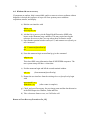
Throughout this guide, look for text highlighted with a yellow background . This denotes
a command string to be entered by the user, followed by the “return” key denoted as
<cr>, in the command line window.
This manual also includes actions to be taken only by OAs or EM personnel. These
are highlighted in bold blue font. These actions usually involve reboots with root
permission, or resets of electronic hardware. Observers should not be doing this.
3
4
2. Login and Startup
The NEWFIRM observer operates the instrument from the workstation mayall-2 near the
telescope operator. This station has four monitors, which the NEWFIRM software
regards as one big screen.
Log into mayall-2 as 4meter and open a terminal window:
Login window will be displayed on mayall-2
Login as 4meter
Password is ________________________ (also posted on one of the monitors).
At 4meter@mayall-2 prompt, type
xhost + <cr> ; ignore the “disabled” message, it’s not an error condition
Open a second terminal window in the lower left monitor. This window will be
connected to the instrument control computer newfirm, and used to issue commands to it.
So we refer to it as the “command line window” in what follows.
2.1 Startup from command line window
In the command line window, ssh to computer newfirm as user “observer” with
ssh –X observer@newfirm-kp <cr>
PW for “observer” is ________________________ .
At the prompt observer@newfirm-kp, type
nocs start all <cr>
(three words, space between)
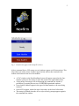
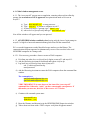
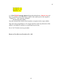
2.2 Startup from icon
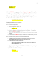
Alternatively, on the lower left monitor, right side, click on the Newfirm icon. This will
open a startup GUI in the upper left corner of this monitor. Click on the blue bar labeled
“Start Newfirm”.
4
5
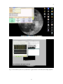
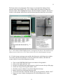
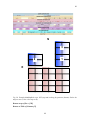
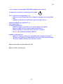
Fig. 1. Newfirm icon (upper) and startup GUI (lower).
After a command line or GUI startup, several windows appear on all four monitors. This
takes about one minute. Some windows appear briefly and are then iconized in the
toolbar at the bottom of the lower left monitor.
•
•
•
•
•
A VNC window to the Data Handling System will appear centered on the fourmonitor system; use the mouse to move this to the lower right hand monitor.
A long string of messages will scroll through the command line window, a
preliminary to opening the next set of NEWFIRM operational windows
Several small windows appear in the upper left hand monitor, with some being
iconized.
Several GUIs appear, stacked on top of each other, in the lower left monitor
The startup is finished when the observer@newfirm-kp prompt appears again in
the command line window
5
6
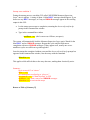
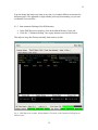
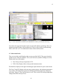
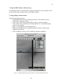
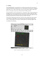
Fig. 2. Screen shots of the lower left and lower right monitors at the end of the startup sequence.
6
7
There are two different errors that may occur during startup. Respond to them as follows:
Startup error condition 1:
If the windows do not appear, and you get a sequence of error messages in the command
line window about “cannot connect”, the host permissions need to be reset on mayall-2:
•
Let the startup process run to completion, returning the observer@newfirm-kp
prompt in the command line window
•
Type in the command line window
nocs stop all <cr>
to stop all processes and close all NEWFIRM GUIs
•
Alternatively, click on “Stop Newfirm” in the startup GUI.
•
Type in the command line window
exit <cr>
•
At the 4meter@mayall-2 prompt, type
xhost + <cr>
•
Reconnect to computer newfirm as before with
ssh –X observer@newfirm-kp <cr>
•
In the command line window, type
nocs start all <cr>
•
Alternatively, click on “Start Newfirm” in the startup GUI.
Now all the windows will appear and you can proceed.
7
8
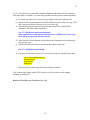
Startup error condition 2:
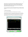
During the startup process, watch the GUI called “NEWFIRM Monsoon Supervisor
Layer” once it appears. A string of about 14 blue RECV messages should appear. If you
do not see any RECV messages, or if any red ERROR messages appear in the scrolling
output in this GUI:
•
Let the startup process run to completion, returning the observer@newfirm-kp
prompt in the command line window
•
Type in the command line window
nmslReset <cr> (that’s en-em-ess-ell-Reset, no spaces)
The system will automatically load the Monsoon Supervisor Layer again. Watch for the
blue RECV and red ERROR messages. Repeat this cycle until the load runs to
completion with no red ERROR messages. If they appear at all, usually one or two
nmslReset cycles are sufficient to get through this.
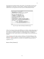
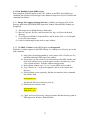
Once the startup has completed without errors and the observer@newfirm-kp prompt has
appeared in the command line window, bias the arrays with the command
400mvbias <cr>
This applies a 400 millivolt bias to the array detectors, making them electrically active.
Summary:
log in to mayall-2 as “4meter”
xhost + <cr>
ssh connection to newfirm-kp as “observer”
nocs start all <cr> or “Start Newfirm” in GUI
nmslReset <cr> in the event of red ERROR messages
400mvbias <cr> to activate the arrays
Return to Table of Contents [2]
8
9
3. Shutdown and logout
At the end of the night, protect the instrument by closing the warm entrance window
cover, and shutting down the array controller and user software.
In the Instrument Control System GUI, close the Environmental Cover. For more about
this, see Sec. 5.
This cover must be closed before the OA closes the telescope mirror covers. Be sure to
coordinate with the OA.
•
Use the Options button in upper left corner of the GUI to enable the button bars
running across the bottom of the GUI.
•
Click the bottom button bar labelled “Close”.
From the command line window in the right hand monitor, type
nocs stop all <cr>
This debiases the arrays, shuts down all processes and closes all GUIs.
Alternatively, click on “Stop Newfirm” in the Newfirm startup GUI.
After all the GUIs have closed, in the command line window type
exit <cr>
This closes the connection observer@newfirm-kp and takes you back to the
4meter@mayall-2 prompt.
From here you can log out of mayall-2 if you like.
Summary:
“Close” button in Instrument Control System GUI
nocs stop all <cr> or “Stop Newfirm” in GUI
exit <cr>
Return to Table of Contents [2]
9
10
4. Setup steps after login and startup
4.1 Setup actions in the DHS VNC window
This VNC window could be moved to any of the four monitors. The lower right one is
convenient for most users.
4.1.1. Start IRAF.
Locate the toolbar of icons across the bottom.
•
•
Left-click on the “CL” icon (the one furthest to the right in the toolbar). This
opens a menu.
Click on “Restore” in this menu.
This opens an xterm with IRAF running in it, set to the mscred package. This is called the
“IRAF cl window”. This is primarily useful for image display to the DHS ximtool with
mscdisplay and interactive image querying with mscexamine tools. The “msc” prefix
denotes IRAF tasks that operate on multiextension FITS files, originally developed for
the Mosaic optical imager.
4.1.2 Change directories to your data directory.
The startup process automatically sets the image root name, and creates a directory for
raw and processed images. In the IRAF cl window just opened, the path for data
directories is
/nfdata/observer
Directories have numerical names in the form year-month-day based on the local (MST)
date at startup, e.g. 20120231. You’ll see directories from previous nights there, as well
as the one for the present MST date.
You may create and use different directory names, and/or subdirectories for raw and
processed data, using the IRAF command mkdir in the IRAF cl window.
I recommend creating a subdirectory for processed data within your raw data directory.
This will receive output from the Quick Reduction Pipeline.
Once created, set the path to your data directory in the IRAF cl window with the usual
IRAF command
cd /nfdata/observer/[directory name] <cr>
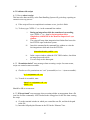
4.1.3. Rearrange the window layout to your liking.
10
11
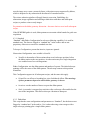
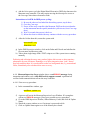
The Figure shows one arrangement. Raw images are automatically displayed from
memory in the image display. The z.super window shows the progress of data from
memory to disk, with a highlighted message when this transfer is complete. The mosdca
window is infrequently needed and can be positioned partially behind one of the others.
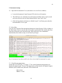
Fig. 3. VNC window to Data Handling System, rearranged by the observer. Raw and Processed
image directories have been set. The z.super window shows the acknowledgement messages.
4.1.4. Set the image root image name and the data directories in the Supervisor window.
You need to enter the desired name or directory path in this window, and check the
z.super window for an acknowledgement message.
•
•
•
•
•
•
•
•
Click on the NEWFIRM DHS Supervisor window to foreground it.
Click on the “Paths and Files” tab.
Find the root filename and image directories in the boxes near the top of the page.
Set the raw image directory path, and hit “enter”.
Check the z.super window for an acknowledgement message.
Repeat for the processed image directory path.
To reset the root name, delete the default, type in your preference, and hit “enter”.
Image root name changes do not generate an acknowledgement in z.super
window
11
12
You can change the image root name at any time, for example different root names for
different targets. The appended six digit number just keeps incrementing, so you can’t
accidentally overwrite data.
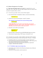
4.1.5. Start automatic flushing of the DHS memory
•
•
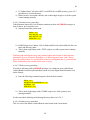
In the DHS Supervisor window, click on the Shared Memory Cache tab.
Click the “ Continuous Polling” box at page bottom to activate this feature.
This helps to keep data flowing smoothly from memory to disk.
Fig. 4. DHS Supervisor window, Shared Memory Cache tab, with Continuous Polling box at
bottom center.
12
13
Summary:
Open IRAF window from the row of icons at bottom of display
Arrange desktop to your liking
Go to NEWFIRM DHS Supervisor -> Paths and Files
Create root image name, hit “enter”
Click on raw image directory path, hit “enter”, verify path in z.super window
Click on processed image directory path, hit “enter”, verify path
Switch to NEWFIRM DHS Supervisor -> Shared Memory Cache
Click “Continuous Polling” box at page bottom to activate this feature
4.2 Setup actions in other monitors
The lower left monitor has the terminal window (=command line window) and a large
number of GUIs stacked up (Fig. 2). These need to be rearranged for more convenient
access.
4.2.1 Set and save Project Parameters
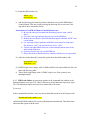
Locate the small “Set Project Parameters” GUI. Fill out the entries in this GUI and click
Save. The GUI will close.
This information is used for data archiving, including access permission for the
astronomer(s) on the proposal. “Actual Observer” means the astronomer who is at the
telescope doing the observing; this is not always the PI. “Proposal Identifier” is your
proposal number, e.g. 2008A-0035. This can be found on the online telescope schedule at
http://www.noao.edu/kpno/forms/tel_sched/ .
_______________________________________________________________________
VERY IMPORTANT: After filling out and saving the Project Parameters GUI, type in
the command line window
nocs set project <cr>
This command uses the information entered in the Project Parameters GUI to actually set
access permission, and synchronize what the NEWFIRM system is producing with what
the NOAO Science Archive is expecting (from the telescope schedule).
_______________________________________________________________________
The Project Parameters GUI can be reopened from the script generating GUI (Sec. 6.1) to
make changes; for example, if two different programs are splitting a night.
13
14
4.2.2 Reposition other GUIs
Look at the larger GUIs on the lower left monitor. These are stacked or overlapping and
need to be positioned for better access. They are:
•
NOAO Extremely Wide Field Infra-Red Mosaic Imaging Camera (called NGUI
for short). This is the script generating GUI. Its use is discussed later in this
document.
•
NEWFIRM Telescope Control System. Allows user control of telescope offsets.
Other capabilities are disabled.
•
NEWFIRM Instrument Control System. Allows user positioning of filters and
warm dust cover.
•
NEWFIRM Monsoon Supervisor Layer. Shows progress of integration and
readout
•
NEWFIRM Observation Header System. Tracks images and header information
as they are assembled into FITS files on disk.
The following rearrangement has proven useful:
•
•
•
•
•
•
Minimize the Observation Header System GUI to the toolbar across bottom of
screen. Observers rarely use it.
Move the Monsoon Supervisor Layer GUI to the upper right monitor. You will be
watching the integration countdown and other activity scroll past in this window.
Position the Telescope Control System and Instrument Control System GUIs
across the top of the lower left monitor. They will overlap slightly.
In these two Control System GUIs, activate their button functions:
o Click on Options in the toolbar, upper left
o Click on Enable in the menu that pops up
o The buttons across the GUI bottom change from grey text to black text
Position the large script-creation GUI “NGUI” in the lower left corner of this
monitor.
The command line window is already in the lower right corner. Leave it there.
The four windows that you will interact with while observing are now readily visible and
accessible on the lower left monitor.
Summary:
Enter and save project parameters in the small GUI
Enter nocs set project <cr> in terminal window
Rearrange GUIs, grouping the ones you will be using in the lower left monitor.
14
15
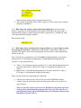
Fig. 5. Lower left monitor with GUIs and command line window positioned for observing.
Next look at the upper left monitor. It has several small windows stacked up. These are
engineering status displays with scrolling text. They are only used for troubleshooting.
These can be left “as is” or minimized to reduce clutter in this monitor.
4.3 Other useful tools
There are two other useful displays that are not part of the NOCS. They may already be
opened on one of the four monitors. If not, start each one by double-clicking on its icon,
found on the lower left monitor:
•
•
Truss Temp: telescope temperatures GUI
VDU (Video Display Unit): telescope and instrument status
Position these displays in the upper left and upper right monitors for quick visual checks.
The Truss Temp GUI displays telescope truss, primary mirror, and ambient temperatures.
Any of these will change from green to red background if that temperature changes by
more than 1 degree C since last the observer reset. This is useful for tracking temperature
changes that affect telescope focus.
15
16
The VDU display shows much useful information about the telescope and instrument; see
the Figure.
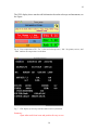
Fig. 6. Truss temperature GUI. “Trs” is the steel telescope truss, “Mir” the primary mirror, and
“Amb” ambient air temperature in the dome.
Fig. 7. VDU display of telescope and instrument status information.
Summary:
Open other tools from icons and position for easy access
16
17
Return to Table of Contents [2]
17
18
5. Instrument startup
5.1. Open the Environmental Cover (warm dust cover over Dewar window):
•
Locate the Instrument Control System GUI in the lower left monitor.
•
This GUI has a row of buttons across the bottom with filter names, and a second
row below this one with two large buttons labeled “open” and “close”.
•
Click the large button on bottom row labeled “open”. It will turn green when the
Environmental Cover is open.
5.2 Select filter:
You can select a desired filter through the Instrument Control System GUI by clicking on
the filter button. Since it can take up to 60 seconds to position the filter wheels, this saves
some time at the start of an observing script. Filter selection is also commanded
automatically from within a script, so, no harm if you forget.
Fig. 8. Instrument Control System GUI with J filter selected and Environmental Cover open.
5.3. Check Dewar temperatures:
Look at the TCS VDU (Sec. 4.3, Figure 7). Two critical instrument temperatures are
displayed at bottom right. These are the temperatures of the internal cold Optical Support
Structure (OSS), and the array detectors. These should read
OSS: 65.0 K
ARRAY: 30.0 K
18
19
If either of these values does not match the above value, contact your observing support
person or the Instrument Scientist before proceeding with observations.
If the array temperature is more than 0.5 K out of range, safety features in the software
will not allow you to take data.
Summary:
Open Environmental Cover via Instrument Control System GUI
Check critical Dewar temperatures on telescope status display
Return to Table of Contents [2]
19
20
6. Data acquisition with scripts
Sec. 6.1 [20] has information and instructions that apply to all scripts.
Secs. 6.2 [24], 6.3 [28], and 6.4 [43] describe the observing scripts, from simplest to most
complex. New users are strongly urged to read through each of these descriptions and
examine the associated script GUI. Each successive script description assumes
knowledge gained by reading its predecessors. The Instrument Scientist or startup person
can also be consulted about which scripts, and what parameter values within them, are
best to use for your observations.
6.1 Creating and using scripts
All NEWFIRM images are taken by executing a script—even test exposures. Scripts are
created using the script editor NGUI. For compatibility with the NEWFIRM science
reduction pipeline, scripts are limited to the choices defined by buttons in NGUI. There
are scripts for darks, test exposures, focus sequences, dome flats, single telescope
pointings (including dithers) and multi-pointing maps. Clicking on any of the script
selection buttons at the bottom of NGUI launches a script-specific GUI, divided into
subsections called Configurations, with user selectable options and user-set parameters.
The button “What’s This?” at the bottom of each script GUI pops up a short description
of the purpose and operation of the script.
Above the script selection buttons in NGUI are two rows of options flags that enable or
disable certain actions in all scripts. The default options have been chosen from observing
experience and should only be changed in consultation with your support scientist. They
will be referred to in the descriptions of individual scripts below.
Many scripts contain a section for Telescope Configuration, in which most of the
parameters have been disabled. Relative offsets are enabled for some scripts. Absolute
pointing to RA, Dec is disabled in all scripts.
Scripts are stored in /home/observer/exec.
20
21
Fig. 9. Script editor NGUI with buttons for script selection.
6.1.1 To create, name, and save a script
To create a script (i.e. to set parameters in an existing script GUI), click on the
appropriate script selection button at the bottom of NGUI. This will open the scriptspecific GUI.
In every script GUI, the Script Configuration allows you to enter an Object Name and a
Script Name. The Object Name is the “title” keyword in the image FITS header. It should
be short, descriptive, and meaningful to you and for that observation.
You will execute the script by typing the Script Name in the command line window.
Name your script something specific and logical to you, and not too long.
To save a script, click “OK” at the bottom of the script GUI. If a script with that name
already exists, you will be asked whether or not you wish to overwrite the previous
version.
“What’s This?” opens a short description of the purpose and operation of the script.
If you decide not to create a script after all, click “Cancel”.
All scripts are saved in the exec directory, /home/observer/exec. The Instrument Scientist
may delete scripts at this level without notification to clean up the directory from time to
21
22
time. If you wish to save scripts for future use, create a subdirectory with your name (e.g.
/ProbstScripts) and copy your scripts into this directory.
Fig. 10. Simple script GUI showing Object Name and Script Name entries (top); and “OK”,
“What’s This?” and “Cancel” buttons (bottom).
6.1.2 To execute a script
After creating a script and clicking “OK” in the script GUI, type “rehash” in the
command line window:
rehash <cr>
To execute the script, make sure that you are in the /home/observer/exec directory, and
type its name as [scriptname].sh in the command line window
<scriptname>.sh <cr>
( for example, Dark5s.sh <cr> )
If a script does not execute (command line window returns an error message), check to
see that
• You are in the correct directory
• A script exists with that name
• The script is an executable file
6.1.3 To abort a script in progress
This has to be done carefully, or the Data Handling System will get tied up, requiring an
extensive recovery process.
If the script will run to completion in a minute or two, just let it finish.
To abort, the command must be issued while an integration is in process. Examine the
Monsoon Supervisor Layer GUI, upper right monitor, and verify that the integration
countdown is proceeding. Then follow these steps:
i.
During integration while the countdown is proceeding; type CNTRL-C
<cr> in the command line window.
22
23
ii.
The window will display instructions about how to proceed. These are the
same as what is written here below.
iii.
Let the integration run to completion, until you see the message DONE in
the Monsoon Supervisor Layer window.
iv.
The script will stop when integration has finished but it leaves the last FITS
file open in the data system. This has to be closed.
v.
Issue this command in the command line window to close the last FITS file:
ditscmd nohs nohs_endobs <cr>
vi.
In the z.super window within the VNC DHS window, check that the last image
was written to disk.
vii.
You are ready to take data again.
6.1.4 To inspect or edit a script
A script can be inspected in the command line window (or in a separate xterm window
logged in as observer@newfirm-kp) using your favorite text editor. This capability can be
used to check input parameters near the start of the script. If the pattern of telescope
positions on the sky is not what you expected, you can scroll through the script and check
the sequence of offset commands to see how your input was translated into telescope
motions.
Scripts are text files, so a text editor can also be used to change parameters without
creating a new script via a GUI. However, using the GUI is likely to be faster and less
prone to error, or to omissions in the repetitive metadata blocks in the script used by the
reduction pipeline.
6.1.5 To create a script of scripts
GUI-created scripts can be strung together as a sequence, to make observing more
efficient. You have to create a new script, which is just a line-by-line listing of existing
script names. The resulting script must be in /home/observer/exec and be executable.
For example, to automatically run a set of dark scripts at various exposure times, gather
the script names into a list file denominated as a shell script, e.g. “DarkSequence.sh”.
Execute this script to run all the dark scripts sequentially. You can do this in the
command line window using your favorite text editor. For example,
23
24
vi DarkSequence.sh
dark5s.sh
dark30s.sh
dark100s.sh
dark300s.sh
:wq
will create the script DarkSequence that runs existing scripts for 5, 30, 100, and 300
second darks in succession.
NOTE: The telescope needs to be refocused when changing filters, and this cannot be
done from a script. The telescope operator does focus changes. So it’s inadvisable to
create a sequence of scripts in different filters.
6.1.6 To download a copy of NGUI
New NEWFIRM observers may find it useful to download NGUI to practice creating
observing scripts. The latest version of NGUI may be downloaded from the NEWFIRM
web site:
www.noao.edu/ets/newfirm
Scroll down the left hand table of contents to “Observing with NEWFIRM”. Click on
“NOCS Script Generator Tool” to retrieve a tarfile. The tarfile contents include a
README file with instructions for installation on your system. While this downloadable
copy of NGUI is useful for practice in making scripts, the resulting scripts may not work
at the telescope. NGUI uses the filter position number, not the filter name, to create
scripts. The list of filters in this demonstration version of NGUI may not match the list
actually installed in NEWFIRM at the time of your observations.
Return to top of Sec. 6 [20]
Return to Table of Contents [2]
6.2 Calibration and telescope setup scripts
Secs. 6.2, 6.3, and 6.4 describe all the NGUI scripts, from simplest to most complex.
New users are strongly urged to read through each of these descriptions and examine the
associated script GUI. Each successive script description assumes knowledge gained by
reading its predecessors.
Here we describe scripts used to take dome-closed calibration data, and to get the
telescope pointed and focused on sky.
24
25
NOTE: the Quick Reduce Pipeline requires appropriate Dark and Dome Flat Sequence
data taken with these scripts. Be sure to do this the afternoon of your first night. See
Section 8.
6.2.1 Dark
“Dark” is the simplest script, with the smallest number of user adjustable parameters. To
start, click the Dark button in the script selection NGUI. This script has three
Configuration sections: Script, Observation, and Monsoon Configuration.
Consult with your startup person about the instrument and telescope configuration in
which to take Dark frames. If in doubt, take darks with the Environmental Cover closed,
telescope mirror covers closed, and the dome darkened.
Script Configuration: user variables are Object Name and Script Name.
•
Object Name is the “title” keyword in the image FITS header. It should be short,
descriptive, and meaningful to you and that observation. Use only alphanumeric
characters and the space bar.
•
Script Name should be something short that readily identifies the script, e.g.
Dark5s for a five second dark integration.
Observation Configuration: user variable is NumObs.
•
NumObs is the number of images to be recorded to disk.
The Filter selection in this Configuration is fixed as Dark.
Monsoon Configuration: user variables are intTime, coadds, fSamples, and digAvgs.
These define parameters for array operations in the Monsoon array controller. Since dark
frames are usually taken for dark subtraction from on-sky data, the user-entered
parameters under Monsoon Configuration should match the on-sky data configuration.
•
intTime is the basic integration time—the amount of time that will be spent
collecting photons before the arrays are read out.
•
coadds is the number of integrations to take in sequence and sum into a single
image which will be written to disk. A coadded image is written as a sum, not an
average.
•
fSamples is the number of Fowler samples to do in each intTime. fSamples=1 is
recommended for sky background limited observations with broadband filters.
Larger values of fSamples are for use with narrowband filters, to reduce readout
noise when it is a significant noise contribution.
25
26
•
digAvgs sets the value of a digital high frequency filter in the readout electronics.
The default value of 4 is recommended for broadband and most narrowband
filters. Larger values may help with noise reduction with very narrow bandpass
filters.
Fig. 11. DARK script GUI configured to take 50, 10 sec individual dark frames (coadds = 1).
fSamples =1 and digAvgs = 4 are the default values for broadband filters.
6.2.2 Test
“Test” is a very simple script. It enables filter selection in the Observation Configuration,
so external photons can be detected. “Test” is used for quick snapshots to check dome flat
or sky signal levels, confirm telescope pointing, etc. The science pipeline will ignore any
data taken with a Test script. Raw images are archived but not further processed.
Observation Configuration: filter selection is enabled. The button is to the LEFT of the
filter name.
Fig. 12. TEST script GUI, configured to take one 5 sec integration in the H filter.
6.2.3 DomeFlatSequence
This script is used to take dome flats for the Quick Reduction and Science pipelines.
These flats are essential to the reduction process. This is not entirely automatic. The
observer must be present to turn the flatfield lamps on and off, and to set lamp levels. The
script includes pauses and advisory prompts for these purposes.
You must use DomeFlatSequence for all dome flats, even if doing flats in only one
filter.
Sec. 8 below has instructions for how to take dome flats, and a table of recommended
lamp level and exposure time for each filter.
26
27
Observation Configuration: select the filters for which you want to take flats.
•
NumObs is the number of images recorded to disk for each filter, typically 10
The GUI expands to allow you to set parameters for each filter selected: intTime, coadds,
fsamples, digAvgs.
•
intTime is selected to get a good exposure level, 2000-4000 ADU
•
coadds is set to 1
•
fsamples is set to 1 for broadband filters, higher values for narrowband filters
•
digAvgs is set to 4 for broadband and most narrowband filters, higher values for
extremely narrowband filters
The values for fsamples and digAvgs should match the values for on-sky science data
taken with the same filters. Read noise reduction is an issue with narrowband filters,
hence the higher values for these cases.
When the script executes, first it goes through the filter sequence, taking images, with the
dome lamps off. Then it repeats with dome lamps on, prompting the user for each filter to
set the lamps at the appropriate level.
Execution will stall if a filter wheel does not position properly, and the script must be
aborted. Any data taken up to that point are useless to the pipelines. I recommend doing
filters in batches: J H Ks first, then narrowband filters in a separate sequence.
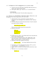
Fig. 13. Dome flats sequence script DFLATS. This script will take 10 observations in each filter
J, H, Ks. The integration time is different for each filter. The dome lamp setting for each filter
must be manually set by the observer as the script proceeds.
6.2.4 Focus
“Focus” takes a series of images, stepping the telescope focus in between. This script
adds Telescope Configuration to the configurations. The script first offsets the telescope
27
28
and acquires a “sky” frame, then offsets back to the initial position and takes an image at
each focus step. These are analyzed with an IRAF routine. For more information on the
focus process, see Section 9 below.
Telescope Configuration: user variables are the parameters for the focus sequence:
•
RA, Dec, and Epoch are disabled. Leave these parameters “as is”.
•
OFFSET RA, Dec define the initial offset for the sky frame, in arcseconds. RA =
30 and Dec = 0 are reasonable choices.
•
FOCUS Start Focus, Step Size, # Focus Steps define the focus sampling.
o Start Focus is the starting value of telescope focus
o Step Size is the focus increment for each step
o # Focus Steps is the number of steps
Start Focus value should be several steps less than your initial estimate of best
focus. Step Size = 50-100 and # Focus Steps = 7-10 are good choices.
Output images are analyzed with the focus analysis software tools described in Section 9
below. Section 9 also describes observational procedures and rules of thumb for focusing.
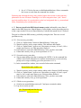
Fig. 14. FOCUS script. This example takes one 10-second observation in the J filter at each
focus step. The sequence starts at telescope focus 10500, and takes 8 frames stepping by 50 units,
to end at 10850. The script takes nine images in all; the first image is offset 30 arcsec in Dec and
used for sky subtraction by the focus analysis routine. Note that the user-assigned Script Name is
not quite right!
Return to top of Sec. 6 [20]
Return to Table of Contents [2]
6.3 Simple observing scripts; dither patterns
The two scripts described here enable observing at a single telescope pointing, including
dithers (small telescope motions) and multiple integrations. These are often used for
targets that do not have extensive, continuous nebulosity. The science reduction pipeline
28
29
uses the image set to create a mean sky frame, with point sources suppressed by dithers,
which is adequate for sky subtraction in the absence of extended sources.
The science reduction pipeline will apply linearity correction, flatfielding, sky
subtraction, image registration and stacking to data taken with these and subsequent
scripts, to produce science-ready images.
Pay attention to the dither geometry discussion—the same choices recur in all subsequent
scripts.
If the NEWFIRM guider is used, dither patterns must remain within bounds for guide star
acquisition.
6.3.1 Standard
“Standard” adds Dither Configuration for telescope dithering capability. It is used for
standard stars. The data are flagged as “standard star” in the archive and are not
proprietary. Other users can retrieve standard star data.
Telescope Configuration: present but inactive; inputs are ignored.
Observation Configuration: user variable is NumObs.
•
NumObs is the number of observations taken at each telescope position, before
the dither motion to the next position. An observation may be a single integration
or a coadded sum of several integrations.
Dither Configuration: sets the dither pattern and number of repeats. The initial telescope
pointing will be the center of the dither pattern. The telescope returns to this position
when done.
This Configuration appears in all subsequent scripts, and the same rules apply.
•
RA and Dec set offsets or bounding box sizes for dithered offsets. The meanings
of these parameters depend on which dither geometry is chosen.
•
Iterations sets the number of times to repeat the dither pattern.
•
Settle, in seconds, is an open-loop wait time after a telescope offset and before the
start of the integration. This allows telescope vibrations to damp out.
6.3.2 DitherStare
This script has the same configurations and parameters as “Standard”, but the data are not
flagged as “standard star” in the archive. Use it when observing science targets with a
single telescope pointing plus a simple dither pattern.
29
30
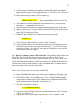
Fig. 15. STANDARD script GUI. Settle time set to 0 reduces overhead, at the expense of some
image blurring from telescope shake following a move. See Fig. 17 below for more information
on the 5PX dither configuration.
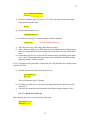
Fig. 16. DITHERSTARE script GUI. Settle time set to 15 sec is very conservative. See Fig. 20
below for more information on the Random dither configuration.
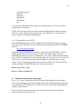
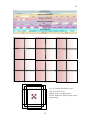
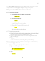
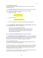
6.3.3 Dither patterns
The dither geometry choices in Dither Configuration define the pattern of motion. Dither
pattern size is set by RA and Dec parameters, which have variable meanings. All patterns
are centered on the initial telescope pointing, and return the telescope there at the end.
•
5PX is an “X” pattern with integrations at each corner, and in the center
o RA and Dec offsets are the distances from center to corner, not corner to
corner
•
RA x Dec is a rectangular pattern. An m x n grid pattern is stepped through in
successive pointings, beginning in the southeast corner and offsetting north and
west.
30
31
o RA and Dec offsets are the distances between successive points
Setting m = 1 and n = 1 will result in no dithering—one telescope position only, at
the initial telescope pointing.
•
4Q moves the target to the center of each quadrant of the mosaic, in succession.
This is a fixed, and very large, dither pattern.
o RA and Dec offsets do not apply to this geometry.
o Quadrant to quadrant motions exceed bounds for guiding.
•
Random generates a bounded irregular pattern. At each successive step, an RA
and a Dec motion are chosen randomly with a value between zero and +/- the RA
and Dec parameters.
o RA and Dec also set the boundaries within which the telescope is
randomly pointed, ±RA and ±Dec from the initial telescope pointing.
o Selecting “Allow Brownian motion” in the NGUI options will choose an
unbounded random walk pattern. This is not recommended.
•
From File moves the telescope using a user-created list of successive relative
offset positions. Consult with the Instrument Scientist or observer startup assistant
for use of this option.
o RA and Dec offsets do not apply to this geometry.
Setting Iterations > 1 will repeat the pattern. If using the guider, the pattern will be fixed
on the same detector pixels pretty closely, which may not be desirable. If not guiding,
telescope-tracking drift will offset the pattern on the detector from cycle to cycle by a
slight amount. To introduce deliberate offsets, use a mapping script such as DeepSparse.
The total number of coadded integrations taken of the standard star will be
NumObs x (number of positions in dither pattern) x Iterations
Figures 17 – 21 below illustrate these dither geometries. Each figure shows the
STANDARD script GUI with appropriate entries for a chosen geometry, and a drawing
of the pattern traced out by the standard star on the NEWFIRM focal plane.
31
32
Fig. 17. STANDARD script GUI with 5PX dither geometry. Four, 3 second observations at the
corners of a box 400 arcsec (RA) x 800 arcsec (Dec), plus a fifth observation at box center =
starting telescope position. Settle time = 0 reduces overhead at the expense of some image blur
from telescope shake. The on-sky pattern shown assumes a manual telescope offset NE from the
initial telescope pointing, before starting the script, so the box-center position doesn’t fall into the
gap between arrays.
32
33
Fig. 18. STANDARD script GUI with RA x Dec dither geometry. With 70 arcsec spacing between
points, the 3 x 4 dither pattern defines a 140 x 210 arcsec box. The telescope has been manually
offset NE from the initial telescope pointing so all dither positions lie in one quadrant (one
detector) of the focal plane.
33
34
Fig. 19. STANDARD script GUI with 4Q dither geometry. Predetermined offsets put the star in
the center of each quadrant of the focal plane mosaic in succession.
34
35
Fig. 20(a). STANDARD script GUI with Random dither geometry. With RA = Dec = 120 arcsec,
the specified 11 steps will lie within a 240 x 240 arcsec box. The telescope has been manually
offset NE from the initial telescope pointing so this box will be in one quadrant (one detector) of
the focal plane.
35
36
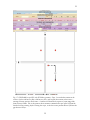
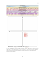
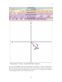
Fig. 20(b). Enlargement of the sequence of telescope positions generated by the Random script
generator. The open circle marks the starting point after manual telescope offset, which is also
the center of the pattern. Integrations are taken at the red positions. The first and last dither
moves, dotted lines, are from and then returning to the pattern center.
36
37
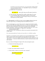
Fig. 21(a). STANDARD script GUI with dither pattern “From File”. The first telescope motion
moves the star out of the central gap between arrays. The last motion recenters it. The pattern
has been defined so that the star position does not repeat any row or column, and the separation
between images adjacent in time is many tens of arcsec.
37
38
File stdpattern.txt
123. 158.
105. 70.
-70. 70.
140. -35.
-35. -140.
-263. -123.
Fig. 21(b). The file of telescope motions that generates the pattern shown in Fig. 21(a).
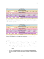
The figures used above to illustrate dither patterns show these from the point of view of
the detector: where on the focal plane mosaic does a single point in the sky (in the
examples, a standard star) lie at any point in the pattern? For science targets, which may
be extended sources or a defined area of sky with many small sources, it is useful to ask
what the coverage looks like on the sky—how is a given area of sky being sampled?
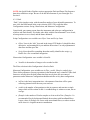
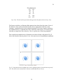
First consider an extended source of moderate size observed with a 4Q pattern. Fig. 22
shows this from the detector point of view—the source moves from quadrant to quadrant.
Fig. 22. Integrations on an extended source with a 4Q dither pattern, from the detector point of
view. The source moves around the 2x2 mosaic of individual detector arrays.
38
39
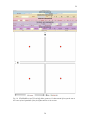
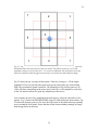
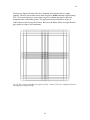
Fig. 23. Integrations on an extended source with a 4Q dither patter in terms of sampling on sky.
Red dashed lines show the actual 2x2 detector mosaic. The pattern on the sky is 3x3, with
quadrant-sized pieces of sky observed 1, 2, or 4 times as indicated. The fixed offsets of the 4Q
pattern are defined so that the gaps between arrays are filled in the final composite image.
Fig. 23 shows the sky coverage of this pattern. Total sky coverage is ~2X the singlepointing FOV by area, but the time spent at any given point on the sky, and resulting
SNR, have pronounced spatial variations. The advantages of 4Q for this source are (i)
100% efficiency integrating on the source and (ii) the sky is well sampled by each array
in the 2x2 detector mosaic for good sky subtraction on the source.
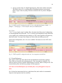
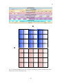
Next consider an area of sky with dispersed small sources, observed with an RA x Dec
pattern. Fig. 24 shows the DITHERSTARE script GUI that defines the observations. Fig.
25 shows the detector point of view: how the field center of the initial telescope pointing
moves around the focal plane. Notice that the offsets between dither pointings are larger
than the gap between detectors.
39
40
Fig. 24. Script defining the dither pattern shown in Figs. 25 - 27. This RA x Dec pattern uses 3 x
4 positions, with different offsets in RA and in Dec.
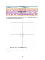
Fig. 25. Observation with an RA x Dec pattern: detector point of view. The X’s indicate how the
field center of the initial pointing moves around the focal plane. This is a 3 x 4 pattern with
spacings of 105 arcsec in RA and 70 arcsec in Dec.
40
41
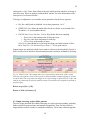
The next two figures show how the sky is sampled, and compares this to a single
pointing. The area of maximum source time-on-pixel is smaller than the single-pointing
FOV. Over most of this area, source time-on-pixel is uniform and equal to the total
integration time of the dither pattern. The gap between arrays introduces stripes of
reduced time-on-pixel across field center. But, since the dither offsets are larger than the
gap, spatial coverage is still continuous.
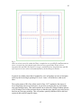
Fig. 26. Sky coverage of the RA x Dec pattern of Figs. 24 and 25. The sky is sampled with twelve
overlapping telescope pointings.
41
42
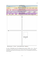
Fig. 27. Observation with an RA x Dec pattern: time on source. The single-pointing FOV is
shown in red. An area of sky within this (blue) is sampled at every pointing for maximum time on
source, except for the cross-shaped region where the array gaps produce stripes of lower
integration time and SNR. The total sky coverage is outlined in green. Integration time and SNR
taper stepwise to lower values in the frame defined by the blue and green outlines.
In general, any dither pattern that is bounded by a box will produce an area of maximum
sensitivity that is the single-pointing FOV less a “frame” of half the box width on all
sides.
The regular pattern of RA, Dec offsets used for Figs. 24-27 emphasizes the stripes of
lower integration time across field center, by precisely overlaying the row and column
array gaps multiple times. This reinforcement can be reduced by using a Random pattern,
or by creating a file of offset positions chosen so that the array gaps do not overlap on sky
between any telescope pointings. This will produce spatially smoother SNR in the final
registered and stacked composite image.
42
43
Return to top of Sec. 6 [20]
Return to Table of Contents [2]
6.4 Scripts with complex telescope motions
Previous scripts have enabled a pattern of telescope motions around the initial pointing
with the Dither Configuration. Now we introduce a second level of telescope pointings
via the Map Configuration. “Dither” motions and “Map” motions are nested. Starting
from the initial telescope position, the telescope goes to the first pointing specified by the
map parameters. It executes a dither pattern around that pointing, as specified by dither
parameters, ending back at the first map pointing. Then the telescope moves to the second
map position and executes a dither pattern; and so on.
In some scripts below, Telescope Configuration is used to introduce a third level of
motions, for observing “blank sky” positions free of extended emission. Yes, this is
getting complicated!
Scripts with both Dither Configuration and Map Configuration are used to (i) observe
large contiguous areas, and (ii) to subsequently treat the image set as a whole in the
science reduction pipeline. There are two types of usage:
• Efficient observation of large areas containing only point (or very compact)
sources, also yielding a well-defined mean sky image for sky subtraction.
• Observation of extended sources. The Map Configuration is used together with
Telescope Configuration to define “sky” pointings chosen to be free of extended
nebulosity, to observe them intermixed with target pointings, and to flag them for
definition of background mean sky image in the pipeline reductions.
Map Configuration patterns and parameters are the same as for Dither Configuration. The
same rules apply as to location of starting point, how the telescope walks through a Map
pattern, and what RA, Dec offsets mean depending on the chosen Map pattern.
Large (~1600 arcsec) Map offsets displace the telescope by nearly a full NEWFIRM field
of view (with a little overlap for registration). The fixed half-field offsets (~800 arcsec) of
the 4Q pattern can be used to position a moderately extended target on each quadrant of
the array mosaic in succession (and then dither it using the Dither Configuration).
A large Map motion (>2 arcmin) will place a selected guide star out of range of the guide
probe. The Guider Wait option will pause data taking to allow acquisition of a new guide
star at each Map position. This will impact observing efficiency.
One generally thinks of Map motions as “large” and Dither motions as “small”. However,
Map offsets can be any size. Small Map offsets (few arcsec) can be used to quasirandomize the pixel sampling of the sky in an iterated dither pattern, while guiding. This
is useful for very deep imaging of fields containing only pointlike sources.
43
44
6.4.1 DeepSparse
This script adds Map Configuration. Map patterns and parameters are the same as for
Dither Configuration. The same rules apply as to the location of the starting point, how
the telescope walks through a Map pattern, and what RA, Dec offsets mean depending on
the chosen Map pattern.
Telescope Configuration is present but inactive; inputs are ignored.
This script is used for efficient observation of large areas containing only point (or very
compact) sources. It also produces a well-defined mean sky image for sky subtraction.
Map parameters are typically set to offset the telescope by large amounts, to cover the
desired total area. Dither parameters are set to do a dither pattern at each map pointing.
The pipeline reduction uses all images together to define a mean sky image for sky
subtraction.
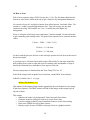
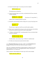
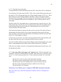
Figure 28 is an example of a DeepSparse script. The map is a rectangular pattern, 3 x 2
positions in RA x Dec. At each map position, a 5 PX dither is executed. E-W shading is
used to denote the individual Map pointings. Heavier lines are the array gaps. The 1600
arcsec map offsets allow ~70 arcsec of overlap between positions, for registration into a
composite image using stars in common. This overlap is also slightly larger than the 60 x
60 arcsec box covered by the dither patterns. This dither pattern, in turn, is chosen to fill
in the 35 arcsec wide array gaps.
44
45
Fig. 28. Example DeepSparse script:
Top: Script GUI entries
Middle: Large scale Map pattern
Bottom: Small scale Dither pattern at each
Map pointing
45
46
6.4.2 DeepRich
Like DeepSparse, this allows two levels of telescope motion, Dither and Map, which can
be used in the same ways. Telescope Configuration is now active and allows a third level
of motion with the Offset parameters in RA and Dec.
Telescope Configuration: user variables are RA Offset and Dec Offset.
•
RA Offset (in arcsec) specifies how far to move the telescope in RA, from the
current map position, to take sky frames; + east, - west.
•
Dec Offset does the same in Declination; + north, - south.
The offsets are applied between Map positions during the dither-map cycle to move off of
an extended target for sky frames. This produces a dithered sky frame set for every Map
position. Note that this is not the same sky pointing every time. The offsets to sky mimic
the Map pattern, offset in RA and Dec. The routine begins and ends with a sky position.
This has proven to be a time-inefficient script when used “full up” for dithering plus
mapping plus sky. The repeated telescope offsets to sky are time-consuming. For many
purposes, they also result in far more sky frames than are necessary.
DeepRich can be useful for observing an extended source that fits within a single
NEWFIRM field of view. In this case, choose “RA x Dec” as the Map option and set m =
n = 1 to get a single Map position. Point the telescope to the target. The telescope will
then offset to the sky position specified in Telescope Configuration; execute a dither
pattern there; offset back to the target and execute a dither pattern there; and then repeat
the sky observations. The reduction pipeline will use only the sky position images to
define and subtract the sky background from the extended source images.
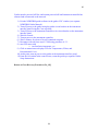
Figure 29 is an example of a DeepRich script. The map on source (pink) is a 3 x 2 pattern
in RA x Dec, as in Fig. 28. Each source map pointing is accompanied by a pointing on
sky (blue). The sky pointings build up a similar pattern. The map offsets are 1600 arcsec
in Dec x 2 Dec positions. The offset to sky from each source pointing is 3200 N in Dec.
As a result, the pattern on sky is contiguous to the pattern on source in this example.
46
47
N
E
Fig. 29. Example DeepRich script. GUI (top) and resulting sky positions (bottom). Pink is the
map on source, blue is the map on sky.
47
48
6.4.3 ModMapRich
Like DeepRich, this allows three levels of telescope motion: dithering, mapping, and
offset to a blank sky position. However, it takes fewer blank sky positions.
Telescope Configuration: new user variable is SkyMod.
•
SkyMod sets the frequency of offsets to sky while executing the Map.
This is best illustrated by examples:
•
For a 2 x 2 raster Map and SkyMod = 4, ModMapRich will do a dither pattern at
the blank sky offset position; all four Map positions; and another sky set.
•
For a 3 x 3 raster Map and SkyMod = 3, ModMapRich will do a blank sky set; the
first three Map pointings; another blank sky set; the middle three Map pointings; a
sky set; the last three Map pointings; and a sky set to end the script.
This results in less clock time spent on large telescope motions, and a more optimal
number of sky frames for definition and subtraction of a mean sky frame, compared to
DeepRich.
Consult with the Instrument Scientist or startup support person for setting the parameters
of this rather complex script.
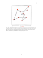
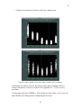
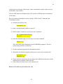
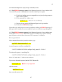
Figure 30 is an example of a ModMapRich script. The map on source (pink) is a 3 x 2
pattern in RA x Dec, as in Figs. 28 and 29. With parameter SkyMod = 3, the script takes
an offset sky frame at the start (sky 1), executes the three position southern row of the
source map in RA, takes another offset sky (sky 2), executes the second, northern row of
the source map, and finishes with a final offset sky position (sky 3). Since the Map offset
= 1600 and the Sky offset = 3600 in Dec, there is a 400 arcsec gap in Dec between the
source pattern and the southerly sky pointings. The script also executes a 5-point dither
pattern at each source and sky pointing.
48
49
N
3
1
2
E
Fig. 30. Example ModMapRich script. GUI (top) and resulting sky positions (bottom). Pink is the
map on source, blue is the map on sky.
Return to top of Sec. 6 [20]
Return to Table of Contents [2]
49
50
7. Using the DHS windows while observing
Two functions of this set of windows are to display and interact with raw images, and to
be sure that the image writing to disk is proceeding normally.
7.1 Image display and interactions
Ximtool image display features:
o Image display shows the raw incoming pixel frame, autoscaled to sky level.
o Orientation is North up, East left.
o Click on the T and C boxes in the toolbar to open up two more toolbars.
o Click on Pan, WCS, and ISM to get an image panner; X, Y coordinate display;
and pixel value display.
o Mag +/- will change the size of the panner box.
o Hold down the right mouse key and pan around the image to change image
brightness and contrast.
o Click on Display to bring up a GUI with these and other capabilities.
Fig. 31. Ximtool image display with toolbars, Pan, WCS and ISM selected.
50
51
Images on the disc can be displayed to the Ximtool with IRAF using mscdisplay in the
mscred package. mscexamine or other tools can interact with the displayed image.
However, if you are taking data, the next raw frame to be read out will overwrite an
image displayed from disc. Imexam etc. tools will not work on the autodisplayed raw
frame since it was not retrieved from the disk.
It may be convenient to go to a separate desktop on the monitor, open another connection
to observer@newfirm-kp, and then open a separate IRAF cl window and Ximtool for data
inspection.
7.2 Monitoring data logging
This is done through the DHS Supervisor Window and the z.super window.
In the DHS Supervisor Window, click on the Shared Memory Cache tab. This displays
the data presently in memory. A complete data set for a single image is five lines of text,
all with the same exposure ID number at the end (ExpID column). Lines of text will
appear and disappear as data are read into memory and then processed onto the disc.
Fig. 32. DHS Supervisor Window – Shared Memory Cache display.
51
52
Processing steps are displayed in the z.super window. The main thing to look for is the
highlighted box with message “Postproc DONE”, updating at regular intervals. This
indicates that a raw image has been written to disk as a multiextension FITS file.
Fig. 33. z.super window with Postproc DONE message
If lines of text begin to build up in the DHS Supervisor Window without disappearing, 10
lines or more, try clicking the Update Status button at the bottom to flush data to disk. It
does no harm to click this more than once, to flush multiple frames. You should see
processing occur in the z.super window as text lines disappear from the DHS Supervisor
Window.
If processing stops and text lines continue to build up, or if the Shared Memory Cache
page turns red, there is a problem. Use the procedures in Appendix A.5 [93]to abort any
script that’s running and then recover from the error condition with the procedures in
Appendix A.2 [75].
Return to Table of Contents [2]
52
53
8. Taking dome flats and darks
Both the Quick Reduce Pipeline and the Science Pipeline require dome flats taken with
the Dome Flat Sequence script to process your on-sky data. Be sure to get these during
the afternoon.
Dark frames that match the science exposures are needed for the best quality Science
Pipeline reduction. Provision of dark frames is critically important for exposures with
low background, especially narrowband images. This requires advance planning of
science exposure parameters for the first night, so that darks can be taken to match in the
afternoon.
8.1 Taking dome flats
Ask the operator to request that the telescope be set up for dome flats at 4:00 p.m.
Use a DomeFlatSequence script to take these data (Sec. 6.2.3). This is necessary for the
pipeline processing. This script allows you to choose which filters to use, and to set the
integration time for each filter. It will take a set with “lamps off” in all filters, and then a
set with “lamps on”. DomeFlatSequence will prompt you to turn the lamps on or off, and
to set them to the desired brightness, at every filter change. Take at least three dome flats
in every filter. The pipeline requires this. I recommend a minimum of ten in every filter
for adequate photon statistics in the flatfields.
Execution will stall if a filter wheel does not position properly, and the script must be
aborted. Any data taken up to that point are useless to the pipelines. I recommend doing
filters in batches: J H Ks first, then narrowband filters in a separate sequence.
The DomeFlatSequence script sets the integration time in each filter. However, lamp
brightness is set manually, so taking a set of dome flats is an interactive process.
Lamp control is via a group of buttons on the telescope console, below the windows to
the telescope, labeled LAMPS. The upper button indicates which set of dome flat lights is
turned on. The middle row of three buttons select high intensity lamps, low intensity
lamps, or off (no lamps). The bottom row of two buttons let you make the selected lamps
brighter or dimmer. A large red display shows the brightness setting.
A toggle switch below the lamp control buttons allows the same buttons to be used to
drive counterweights for balancing the telescope. Be sure this switch is set to “Lamps”.
Here are recommended lamp settings and integration times for each filter. Integration
times were chosen for filters in the J and H bands to give about 3000 ADU of signal. This
is 24000 electrons, or 240000 electrons total in ten frames, for a photon statistics S/N ~
500. Integration times were chosen for filters in the K band so as not to exceed 40005000 ADU in the lamps-on frame (lamp plus background thermal emission). This keeps
53
54
the signal in the linear regime of the detector response curve over the range of individual
pixel raw values that will result. The S/N in the averaged differential frame will be lower
than for the other filters.
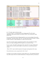
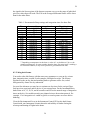
Table 1. Recommended lamp settings and integration times for dome flats.
Filter
J
H
Ks
1066
1187
2096
1644
2122
2168
1056
1063
J1
J2
J3
H1
H2
Lamp setting
Low @ 25
Low @ 15
Low @ 15
High @ 14
Integration time
10 sec
5 sec
1 – 2 sec **
10 sec
Signal level
~ 3000 ADU
~ 3200 ADU
~ 3900 on, 1700 off**
~3200 ADU
Low @ 25
Low @ 20
Low @ 20
High @ 22
High @ 22
Low @ 30
Low @ 30
Low @ 30
Low @ 15
Low @ 15
20 sec
15 sec
15 sec
10 sec
10 sec
20 sec
10 sec
6.5 sec
10 sec
6 sec
~1900 sec
~ 2600 on, 500 off
~ 3000 on, 1000 off
~2800 ADU
~3000 ADU
~ 2800 ADU
~ 3000 ADU
~ 3000 ADU
~ 3000 ADU
~ 3000 ADU
** Depending on temperature in the dome. A value of 1 sec defaults to 1.24 sec, the
minimum readout time. In warm weather when the dome flat screen itself is emitting a
lot of thermal radiation, it may not be possible to get unsaturated Ks flats.
8.2 Taking dark frames
You need to take dark frames with the same array parameters as your on-sky science
data: integration time, coadds, Fowler samples, and digital averages. The Science
Pipeline uses the on-sky data and matching darks to generate source-free, scaled
background sky frames for sky subtraction.
On your first afternoon you may have to estimate on-sky times for the various filters,
from previous experience and/or advice of your setup person. For the broadband filters,
darks taken at 10, 15, 20, 30, and 60 seconds would cover the normal range of integration
times on the sky. Set coadds to match your planned science observation protocol. For
example, 15 sec integration x 4 coadds to get 60 sec total exposure on source before
dithering.
Close the Environmental Cover in the Instrument Control GUI to take dark frames.
Consult with your Instrument Scientist about the advisability of further closing the
telescope and turning off lights in the dome.
54
55
Figure 38: Instrument Control GUI showing configuration for dark frames.
Use the Dark script to take these data. Take at least three frames at each combination of
integration time, coadds, Fowler samples, and digital averages that you plan to use. To
automatically run a set of dark scripts at various exposure times, gather the script names
into a list file denominated as a shell script, e.g. “DoDarks.sh”. Execute this script to run
all the dark sequences (see also Sec. 6.1.5).
8.3 A typical calibration plan
A typical calibration plan for a program doing both broadband and narrowband imaging
would be this:
•
Dome flats in J, H, and Ks filters; using a DomeFlatSequence script, with lamp
settings and integration times from Table 1 above.
•
Dome flats in 1644 (1.64 µm [FeII]), 2122 (2.12 µm H2), and 2168 (2.17 µm Br γ)
filters; using a separate DomeFlatSequence script, with lamp settings and
integration times from Table 1 above.
•
Dome flats done from 4-5 pm with the observer present for required manual
interactions.
•
A sequence of dark frames, 10 each at (5 sec x 12 coadds), (10 sec x 6 coadds),
(30 sec x 2 coadds), and (180 sec x 1 coadd); using separate Dark scripts for each,
bundled into a superscript (Sec. 6.1.5).
55
56
•
Observing times and coadds for dark frames are chosen to match typical use;
change to fit needs of your program. The sequence above provides for short
integrations on brighter sources (5 sec), sky-background-limited integrations in H
and Ks (10 sec) and J (30 sec) with 60 sec on source between telescope dithers,
and single background-limited integrations in narrowband filters.
•
Darks run for 75 minutes while everyone is having supper. Or, at the end of the
night, left to run after telescope and dome are closed up, and observer and
operator go to bed.
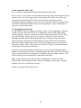
Return to Table of Contents [2]
56
57
9. How to check telescope pointing
The instrument pointing center, used to point the telescope, must be at the science field
center for the guider probe positioning calculations to work. Unfortunately, the science
field center has no pixels in it, due to the ~35 arcsec gap between arrays in the 2x2
mosaic. So we position the pointing check star off center, then offset the telescope by an
amount calculated to put the star at field center, to initialize the pointing.
o At start of night, have Observing Assistant go to a bright star (3-6 mag).
o Take a short integration (1-2 seconds) in Test mode.
o If bright star is not seen in raw image, it may be in the gap between arrays. Offset
the telescope by 100 arcsec in RA and in Dec (via the Telescope Control GUI)
and take another frame.
o You should see the star now. Use the cursor to determine the offset in pixels
between star position and the inside corner of the array it’s on.
o Convert to arcsec at 0.40 arcsec/pixel.
o Add 17 arcsec in RA and in Dec to allow for half the gap between arrays.
o Apply this offset to the telescope to place the star at field center.
o Take a final Test frame to confirm positioning. The star should not be seen.
o Diffraction spikes on very bright stars may be seen. They should radiate from the
inside corner of the active area of each array.
o Ask the Observing Assistant to “ zero the telescope “ at this position. This sets
input coordinates for the star = current telescope position.
I recommend verifying pointing in this manner whenever you go to a new target more
than 30 degrees or so from the previous pointing.
Return to Table of Contents [2]
57
58
10. How to focus
Take a focus sequence using a FOCUS script (Sec. 6.2.4). The first frame duplicates the
first focus value, and is offset on the sky to get a frame for sky background subtraction.
It is easiest to focus in J, and apply a known focus offset between J and other filters. Ten
seconds x 1 coadd is a good integration time for J. This will average out any rapid
variations in seeing. For H and Ks use 5 sec x 2 coadds due to the higher sky
backgrounds.
Focus is a function of telescope truss temperature T and wavelength. Use these formulas
to get reasonably good starting values. Set up the focus sequences to be centered on these
values:
J Focus ~ 12000 – { 100 x T (ºC) }
H focus = J + 100 units
K focus = J + 200 units
Or check with the previous observer or the telescope operator for best focus at the start of
the previous night.
A good step size is 100 units for an initial search, followed by 50 unit steps around the
best resulting focus value to refine the result. Set starting value and number of steps to
bracket the estimated focus with three or four steps on each side.
The truss temperature is obtained from the Truss Temp GUI, Sec. 4.3.
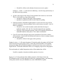
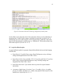
After all the images in the sequence have been taken, run the IRAF focus analysis.
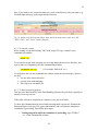
In IRAF cl window (Sec. 3.1.1), type
nffocus [file number] <cr>
[file number] is the running image number appended to the root filename, for any image
in the focus sequence. The IRAF routine will find all the images in the sequence given
any one of them.
This routine
o Subtracts the initial “sky background” frame from each focus frame.
o Generates an object catalog for each array at each focus value.
o Uses the catalog to identify round, unsaturated sources at each focus setting.
o Derives the FWHM for each of these sources.
o Displays a plot of source FWHM vs telescope focus in a graphics window.
58
59
o Displays its solution for best focus value from a fitting routine.
Figure 45: nffocus graphics with coarse (upper) and fine (lower) sampling.
Occasionally, for unknown reasons, the nffocus routine hangs, leaving the IRAF cl
window unresponsive to mouse or keyboard. See Appendix A.2.7 [75] for recovery
procedures.
Visually inspect the plot of FWHM vs. focus setting as a sanity check. Your eye may do
better than the curve fitting routine at identifying the best focus.
59
60
Note the focus value (“solution” and “eyeball”) then type q in the graphics window to
quit this routine, or explore the data further with keystrokes below.
Keystrokes in the graphics window display the analysis in various ways, and can be used
to delete suspect data points:
f
b
t
m
d
x
u
q
plots FWHM vs focus setting (default plot)
plots focus vs various spatial parameters
radial distribution of FWHM
magnitude distribution of FWHM
locate cursor over bad point, hit d to delete it
deletes entire data set for given focus value
reverses last delete action
exits the graphics window (may have to hold down firmly, not
merely tap)
It may be useful to use the “d” (delete) keystroke to remove discordant data points from
the FWHM data sets near the fitted best focus. If the fitted focus solution is stable, it
won’t change much.
If the displayed FWHM vs. focus setting doesn’t have a clearly defined minimum, you
probably haven’t gone through the best focus position. Run the focus script again with a
different START value to try to bracket the estimated telescope focus.
On nights of poor seeing the focus may have a very broad minimum or be undefined.
This may also happen if you have chosen a very star-poor field for the focus test.
Focus stability can be monitored on the science frames as observing proceeds. Both
changing temperature and truss flexure will change the focus. I recommend running a
focus sequence if the telescope truss temperature changes by 0.5 deg C or more, or if you
move across the sky to a new target by more than 30 degrees.
60
61
Here is a tabulation of the focus offset for each filter with respect to filter JX (broadband
J).
Filter
J
H
Ks
1066
1187
2096
1644
2122
2168
1056
1063
J1
J2
J3
H1
H2
Offset
0
+100
+200
+100
+185
+50
+50
0
Return to Table of Contents [2]
61
62
11. Guiding
The NEWFIRM guider is operated by the 4-m Observing Assistant (OA) from the OA’s
telescope control station. The guider uses two cameras that access stars in two rectangular
guide fields via X-Y stages. Each camera can access any position within its guide field.
However, the guide star must stay within the field at all dither positions.
The guide field size is 26.8 arcmin (RA) by 4.4 arcmin (Dec). This constrains dithering in
Declination (N-S). If the chosen guide star is near the N-S centerline of the guide field,
then dithers must remain within ±2 arcmin of the starting position. If the guide star is less
favorably positioned, then N-S dither motions are further constrained.
The guide star display and selection tool, at the OA station, displays the science field of
view and the two guide fields, at the current telescope position, from the Digital Sky
Survey. Consult with the OA to choose a suitable guide star, balancing brightness and
accessibility while dithering.
Figure 48: Guide star display and selection tool.
62
63
There are two overhead costs with guiding: time spent manually selecting and setting up
on a guide star before starting an integration sequence (1-2 minutes) and time needed to
automatically recover the guide star after a telescope dither (a few seconds).
Use of a script that includes Map motions (Sec. 6.4) introduces another complication. A
large Map motion will move a selected guide star completely out of the guide field. The
Guider Wait option will pause data taking to allow manual acquisition of a new guide star
at each Map position. This further impacts observing efficiency.
The most efficient observing mode is to not use the guider. The open loop tracking of the
telescope will deliver round star images for exposure times up to 60 seconds at Dec +32;
longer at more northerly Declinations, and shorter near the celestial equator. For many
programs using broadband filters, 60 sec or less integration time followed by a telescope
dither is a good protocol. One can also select a guide star, but disable guiding, and use it
only as a telescope position check at the end of a dither sequence. This is useful if
observing the same field in multiple filters.
The periodic loss of the guide star when using a Map configuration can be finessed a bit.
For Map positions that will only be used to define “blank” sky for sky subtraction, it
doesn’t matter if the images are a bit elongated, so a new guide star doesn’t have to be
acquired.
Return to Table of Contents [2]
63
64
12. Real time data inspection
There are two ways to inspect your data and evaluate data quality. One is to access the
raw data as they come in, and perform simple image analysis with IRAF. For example,
sky subtraction followed by image quality evaluation using the imexam task provides a
running check on telescope focus.
The other way is to inspect the Quick Reduce Pipeline products. These include sky
subtracted, linearized, flatfielded, shifted and added final frames from dithered
observations. This permits confirmation of detection of sources plus quantitative
evaluation of signal-to-noise.
Both approaches can use the workstation to the right of the NEWFIRM observer’s
workstation so that inspection does not interfere with data taking.
12.1 Inspection of raw data
To the right of mayall-2 is another workstation with multiple screens, mayall-3, where
you can set up a separate data analysis station. This is also the observer’s station for the
MOSAIC CCD camera.
Login as
user: mosaic
password: ____________
Let the VNC session come up (it does so automatically) then kill it. Open a shell-console
window. At the mosaic prompt, open an xgterm:
mosaic@mayall-3% xgterm &
In the xgterm window, ssh to newfirm-kp:
mosaic@mayall-3% ssh -X observer@newfirm-kp
password: _______________
Then start iraf :
[observer@newfirm-kp~]$ cl
Once in iraf, load the mscred and newfirm packages, and open up a ds9 display tool:
ecl> mscred
mscred> newfirm
newfirm> !ds9 &
64
65
Now you can cd to your data directory and access your data.
newfirm> cd /nfdata/observer/[today's_date]
65
66
12.2 Accessing the Quick Reduction Pipeline products
The NEWFIRM Quick Reduction Pipeline web pages are under the purview of Rob
Swaters. At present they may be accessed at
http://www.noao.edu/staff/med/newfirm/QRP/
I especially recommend that observers read the section on “How to observe in a pipelinefriendly manner”.
Questions about the QRP, or reporting of problems with the QRP at the telescope, should
be reported to [email protected].
To access the pipeline products, I recommend using the other multiscreen workstation in
the 4-m control room, mayall-3; or, you could work from a laptop. You need to open
several windows in order to connect to or view several processes simultaneously:
• Open a web browser and point it to
http://nfpipe-01-kp.kpno.noao.edu/NEWFIRM_pipeline/observer/.
This is a web page showing a log of the data that the QRP has processed for your
run so far. Initially, it will be empty until you take data for the QRP to process,
such as dome flats, darks, or your first nighttime observing sequences. You will
need to reload/refresh this web page in your browser periodically. It will be
updated as new data are processed and added to the QRP review log.
• Open one xterm window and log in to the newfirm computer via ssh
observer@newfirm-kp. From there, you can run the plstatus command to check
that the pipeline is running properly.
• Open another xterm window and log in to the nfpipe-01 computer via ssh
[email protected], using the same password as for
observer@newfirm-kp. From there, you can run the dqquery command, which
provides data quality information for images that the pipeline has processed
recently.
• Open an xgterm window and log in to the newfirm computer via ssh -X
observer@newfirm-kp. Open an image display (ximtool or ds9) in the
background, and then start an IRAF session from the /home/observer/ directory by
typing 'cl'. Change directories to go to the location you specified for the QRP
FITS output products (Sec. 4.1.2). You can then display and otherwise analyze
these images as they appear during the course of the night.
The QRP web page (first bullet above) provides access to a wealth of information and to
the QRP images. You will see a log of data that the QRP has processed for your run so
far, with various information about each observing sequence, including:
66
67
o
o
o
o
o
o
o
o
o
image filenames
UT at the start of the observing sequence
observation type
exposure times
filter
focus setting
number of digital averages (DA) and Fowler samples (FS)
airmass
image title
In addition, this log reports the ranges spanned by some data quality parameters that are
measured by the pipeline, such as:
o sky brightness (in ADU and mag per square arcsec)
o seeing FWHM
o magnitude zeropoint estimated from 2MASS stars (useful for monitoring
relative transparency)
o estimated 5-sigma point source sensitivity
Clicking on the image filenames for a given sequence takes you to a pipeline review page
with information about data from that sequence. There are review pages for processed,
combined dark frames and dome flats, as well as for nighttime on-sky observations. For
nighttime science observations, the QRP review pages provide:
o
o
o
o
o
thumbnail pictures of the data
links to images at two different higher resolutions for quick visual checks
basic header information about each image
links to the full FITS headers
data quality measurements (seeing, magnitude zeropoint, depth, etc. - see
above)
For dithered on-sky observing sequences, preview images are shown for each individual
exposure, as well as for stacked mosaics of the observations. The stacked images are
shown in the second column of thumbnail images. If, during the course of an observing
sequence, the telescope motions exceed a particular hardwired tolerance (currently 8
arcmin, but this may change), the QRP will break the sequence into multiple independent
stacks that will all appear in the 2nd column of thumbnail images.
FITS data products: When processing is complete for a sequence, FITS files of the
combined image (the "mosaics" or "stacks") will be delivered to the directory that you
specified for processed images (see Sec. 4.1.2 above). The names of the files start with
NFQR (for NEWFIRM Quick Reduce). FITS files are delivered only for on-sky
observations, not for dome flats or dark calibrations.
Processed image filenames are long and opaque. The key is to look for an image
sequence number. This will be the first image in a data sequence (a set of dithered
67
68
exposures, for example). This can help you trace a processed image file back to the raw
image sequence from which it originated.
The QRP products are not archived, so if you want to save them, move them to your
local hard drive or otherwise retrieve and store them before your run is over. The QRP
log and associated data products will automatically reset for the next observer.
Return to Table of Contents [2]
68
69
Appendix A. Error recovery procedures
Here is a quick functional/symptomatic index to the error recovery procedures. In each
section, the more common problems are presented first.
Procedures requiring OA/EM intervention are highlighted in blue. Hardware
procedures are embedded in the troubleshooting instructions. Instructions for
rebooting the NEWFIRM computers are given separately for each computer in
Section A.7 .
A.0 Kitchen sink error recovery [72]
If symptoms are unclear, help is unavailable, and/or a return to science readiness
without diagnosis is desired, this sequence of steps will clear up many errors with
data acquisition, transfer, and display.
A.1 Global window management errors [73]
A.1.1 No windows or GUIs appear after doing “nocs start all”
A.1.2 All NEWFIRM windows suddenly close
A.2 DHS errors (VNC window to DHS; lower right monitor) [75]
A.2.1 Images don’t appear in image directory
A.2.2 The IRAF cl window in the DHS display has disappeared
A.2.3 The Ximtool in the DHS has disappeared or been accidentally closed
A.2.4 Shared Memory Cache Status window shows a red background
A.2.5 Data are stuck in the DHS shared memory cache
A.2.6 Data aren’t being written to disk as .fits files
A.2.7 nffocus IRAF routine hangs
A.2.8 Data transfers appear to freeze
A.2.9 Integration times out and “nohs nohs_endobs” returns Broken Pipe
error message
69
70
A.3 Instrument control errors (GUI in lower left monitor, or command line window) [84]
A.3.1 Instrument Controller GUI not seen during instrument startup
A.3.2 No communication with Environmental Cover or filter wheels
A.3.3 Filter wheel doesn’t reach commanded position
A.3.4 Can’t move filters and cannot “ssh” connect to nicc.
A.4 Monsoon Supervisor Layer errors (NMSL GUI or command line window) [87]
A.4.1 Red ERROR messages appear during startup
A.4.2 Red ERROR message appears during startup about a timeout error
A.4.3 Red ERROR message appears about a voltage out of range
A.4.4 Monsoon Supervisor Layer window shows a red ERROR message
during integration and readout cycle, while DHS activity appears normal
A.4.5 NMSL task failure error message
A.4.6 Red ERROR message appears during data taking about a timeout error
A.5 Problems with scripts (command line window) [93]
A.5.1 How to abort a script
A.5.2 “Permission denied” error message when executing a script
A.5.3 “File not found” error message when executing a dither or map pattern
from a file (text list of offset commands)
A.6 Problems with appearance of raw images (image display in DHS window) [95]
A.6.1 Raw image has identical count in every pixel
A.6.2 Raw image has negative counts and strange appearance
A.6.3 Raw image shows a strong center to edge gradient, or a vague shape
covering the central part of the field
70
71
A.7 Reboot instructions for NEWFIRM computers [98]
A.7.1 Reboot newfirm-kp
A.7.2 Reboot nfpan-a-kp and nfpan-b-kp
Note power-off and power-on of DHE in the cage!
A.7.3 Reboot nfdca-kp
A.7.4 Reboot nfdhs-01 and nfdhs-02
A.7.5 Reboot NEWFIRM Instrument Controller, aka NICC
A.8 Locations of rack-mounted NEWFIRM computer power buttons [102]
71
72
A.0 Kitchen sink error recovery
If symptoms are unclear, help is unavailable, and/or a return to science readiness without
diagnosis is desired, this sequence of steps will clear up many errors with data
acquisition, transfer, and display.
a) Halt the user interface with
debias <cr>
nocs stop all <cr>
b) Ask the OA to power cycle the Digital Head Electronics (DHE) also
known as the Monsoon array controller. This may require moving the
telescope for access to the Cass cage where these electronics reside.
c) Open another terminal window on mayall-2, and connect to newfirm-kp as
user “monsoon”:
ssh –X monsoon@newfirm-kp
pw ______________________
d) From this monsoon login on newfirm-kp, give the command
zzkpvm <cr>
This clears DHS setup information from all NEWFIRM computers. The
next system startup will have a clean slate.
e) Exit the monsoon login and kill the second terminal window
exit <cr>
(from monsoon@newfirm-kp)
f) Restart the user interface from the existing observer@newfirm-kp login
with
nocs start all <cr>
400mvbias <cr>
(after restart is complete)
g) Check, and reset if necessary, the root image name and the data directories
in the DHS Supervisor Window, Paths and Files.
h) Take a short test frame or two, see if all looks well.
Return to Error Recovery Procedures list [69]
72
73
A.1 Global window management errors
A.1.1. The “nocs start all” process ran to completion, returning observer@newfirm-kp
prompt, but no windows or GUIs appeared: host permissions need to be reset on
mayall-2.
a)
b)
c)
d)
Type “ nocs stop all <cr> “ to stop processes
Type “ exit <cr> “ to return to computer mayall-2
At 4meter@mayall-2 prompt, type “ xhost + <cr> “
ssh to observer@newfirm-kp and type “ nocs start all <cr> “
Now all the windows will appear and you can proceed.
A.1.2 All NEWFIRM windows suddenly close leaving only the 4meter login prompt to
mayall-2: a high level network communications glitch closed all the connections.
We’ve seen this happen once at the Mayall telescope and never at the Blanco. The
communications dropout appeared to spontaneously recover. However this left several
NEWFIRM computers in a strange state.
A.1.2.1 First recovery procedure: observer restart of PAN computers
a) Exit from any other observer@newfirm-kp logins on mayall-2 and mayall-3.
b) Ask the Observing Assistant to shut down and reboot newfirm-kp.
c) Log back in to newfirm-kp from 4meter@mayall-2:
ssh –X observer@newfirm-kp
usual password
d) Ask the Observing Assistant to restart the PAN computers from the command line
window.
The commands are
panTools nuke nfpan-a-kp <cr>
panTools nuke nfpan-b-kp <cr>
VERY IMPORTANT: be sure observer has issued the “nocs stop all”
command first. Otherwise, “nuke” can have catastrophic consequences. If
this makes you nervous, don’t do it. Move on to A.1.2.2 below.
e) Continue with a normal system start:
nocs start all <cr>
400mvbias <cr>
f) Reset the filename and directories in the NEWFIRM DHS Supervisor window
g) Take a short test frame with a TEST script to verify that all appears normal.
73
74
A.1.2.2 Second recovery procedure: complete shutdown and reboot of PAN computers.
This takes about 15 minutes. Try if the first procedure doesn’t produce normal operation.
a) Exit from any other observer@newfirm-kp logins on mayall-2 and mayall-3.
b) Ask the Observing Assistant to turn off the Monsoon power in the Cass cage. This
may require moving the telescope for access to the cage.
c) Ask the Observing Assistant to shut down and reboot PAN A and PAN B
computers. This takes about ten minutes.
See A.7.2 [98] Reboot nfpan-a and nfpan-b.
Note requirement to turn off the Monsoon power (=DHE power) in the cage
first, and turn it back on after the reboots.
d) After both have been rebooted, ask the Observing Assistant to turn on Monsoon
power in the cage.
e) Ask the Observing Assistant to shut down and reboot newfirm-kp.
See A.7.1 [98] Reboot newfirm-kp
f) Log back in from 4meter@mayall-2 to newfirm-kp and do a normal system start:
ssh –X observer@newfirm-kp
usual password
nocs start all
400mvbias
followed by the normal setup activities in all three monitors
Take a short single image with a TEST script to see if the system is now running
normally (it should be).
Return to Error Recovery Procedures list [69]
74
75
A.2 Data Handling System (DHS) errors
Error symptoms generally appear in the VNC window to the DHS. Some DHS error
conditions also produce error messages in the Monsoon Supervisor Layer GUI and/or the
command line window.
A.2.1 Images don’t appear in image directory: probably you forgot to click on the
directory path in the NEWFIRM DHS Supervisor window when the DHS desktop was
brought up.
a) The images are in default directory /home/data .
b) Move or copy the .fits files, and associated .dat, .trig, .txt files to the desired
directory.
c) Go to Supervisor Window, Paths and Files, and do mouse click <cr> on the path
to set it for future images.
d) Look for confirming message in the z.super window.
A.2.2 The IRAF cl window in the DHS display has disappeared.
While the cl window appears in the DHS desktop, it is running on newfirm-kp, not on the
nfdhs machines.
a) It may have been backgrounded by a stray mouse click. Check to see if it
is hidden behind the DHS Supervisor window.
b) If truly gone, go down to the icons at the bottom of the DHS window and
click on an xgterm icon to open an xgterm window. Alternatively, select
“New Xgterm window” from the window manager menu.
c) In the xgterm window, type “cl <cr>” to start IRAF in this window.
d) Type “mscred <cr>” to go to the right task, and cd to the current data
directory.
e) If this problem occurs repeatedly, halt the user interface in the command
line window with
nocs stop all <cr>
and then ask the OA to reboot newfirm-kp.
f) Restart the user interface with
nocs start all <cr>
400mvbias <cr>
g) Check, and reset if necessary, image root name and data directory paths in
DHS Supervisor Window, Paths and Files
75
76
A.2.3 The Ximtool in the DHS has disappeared or been accidentally closed.
a) Go down to the icons at the bottom of the DHS window and click on an
xgterm icon to open an xgterm window.
b) In the xgterm window, type “ximtool & <cr>” to restart the Ximtool
Or alternatively,
Select “New Ximtool window” from the window manager menu.
A.2.4 DHS Supervisor, Shared Memory Cache Status window suddenly shows a red
background: Data Collector Agent process (DCA) has crashed.
a) Check the VNC screen to verify that the z.mosdca window has
disappeared (if not, something else has crashed and we have a different
problem).
b) Close the pending observation file for the last frame. From the command
line window, issue the command
ditscmd nohs nohs_endobs <cr>
This moves data to DHS memory but not onto the disk.
c) Restart the system with
debias <cr>
nocs stop all <cr>
nocs start all <cr>
400mvbias <cr>
d) In DHS Supervisor window, click on Paths and Files tab, and redefine the
file root name and directory paths
e) If you want to save the data in memory, click “Update Status” in the
Supervisor window to list the exposure ID’s ExpID of images in the
memory. These are numeric, e.g. 2454411.609138.
f) Flush these to disk using, repetitively if necessary,
dhsflush <ExpID>
(for example, dhsflush 2454411.609138)
g) This should save the data although the file numbers will be <previous
image filenumber> + <appended letter a, b, c, etc.>
h) The file numbers will begin incrementing normally when the next script
starts.
i) If you don’t care to save the data, use instead
dhsclean <cr>
76
77
j) See A.2.5.3 below for more on dhsflush and dhsclean, if these commands
don’t seem to work from the command line window.
Debiasing and rebiasing the arrays may produce higher dark current or other transitory
phenomena for tens of minutes. Running a set of short integration time “junk” frames
may help stabilize them. It’s not advisable to take low background data, e.g. narrowband
filters, immediately after a debias/rebias cycle.
A.2.5 Data are stuck in the DHS shared memory cache, indicated by many lines of
entries in the DHS Supervisor, Shared Memory Cache display, and no processing activity
in the z.super window. However Shared Memory Cache has not turned red (A.2.4 above).
The goal is to flush the DHS memory, preferably saving the data. There are several
procedures to try.
A.2.5.1. First recovery procedure:
a) Click on “Update Status” button on Shared Memory Cache page.
b) Watch for activity in the z.super window. This indicates data transfer.
c) Click on “Update Status” again to see if the memory is empty; if it isn’t, click a
couple more times to see if this procedure flushes it.
d) If no entries are seen in the Shared Memory Cache, you have succeeded.
e) If data don’t entirely clear, go to next procedure A.2.5.2
A.2.5.2. Second recovery procedure:
a) Stop any data taking script that is running with CNTRL-C in the command line
window. Wait for the integration to complete and return observer@newfirm-kp
prompt. (If no script is running, go to next procedure A.2.5.3)
b) In the command line window, issue an end-of-observation command,
ditscmd nohs nohs_endobs <cr>
c) Watch for activity in the z.super window ending with a Postproc DONE message
d) Click on “Update Status” again to see if the memory is empty; if it isn’t, repeat
steps b-c for a couple more times to see if this procedure flushes it.
e) If no entries are seen in the Shared Memory Cache, you have succeeded.
f) If data don’t entirely clear, go to next procedure
A.2.5.3. Third recovery procedure:
a) Switch to an unused desktop on mayall-2 and open a terminal window
b) Log in to newfirm-kp with
ssh –X monsoon@newfirm-kp <cr>
password is _______________ .
77
78
c) Get the exposure ID number of stuck data from the field ExpID in the Shared
Memory Cache window. The ExpID is numeric, e.g. 2454411.609138. There will
be several lines with the same ExpID.
d) In the monsoon login window you just created, type
dhsflush <ExpID> <cr>
(for example, dhsflush 2454411.609138)
e) This should save the data although the file numbers will be <previous image
filenumber> + <appended letter a, b, c, etc.>
f) The file numbers will begin incrementing normally when the next script starts.
g) Watch for activity in the z.super window and the Shared Memory Cache window
h) Click on “Update Status” again to see if the memory is empty. If it isn’t, repeat
steps d and h a couple more times.
i) If data still don’t entirely clear, from monsoon@newfirm-kp type
dhsclean <cr>
j) You will lose the data in memory with the “clean” procedure
k) Click on Update Status to be sure the memory has cleared. If the exposures are
still shown as present, but with parameter shmId set to –1, it will be necessary to
go through a debias – nocs stop all – nocs start all – 400mvbias cycle to get the
status window to show as empty.
A.2.6 Data aren’t being written to disk as .fits files. This probably indicates that a data
disk is full. There are two disks that can produce this error. One is on newfirm-kp,
/nfdata; the other is on the Data Capture Agent computer, nfdca-kp, /home2/data. You
need to check both disks, and clear off old data to make room. /nfdata and /home2/data
each have the capacity to hold a month’s worth of broadband data, so anything that you
delete has long since been archived and checked.
A.2.6.1 First recovery procedure, to clean off data disks:
a) In the NEWFIRM DHS Supervisor window, Shared Memory Cache page, check
the Disk Usage Bar in bottom right corner. If it reads 100% then /nfdata is full.
b) In the IRAF window, cd to /nfdata/observer. You will likely find many nights’
worth of data in subdirectories. Delete subdirectories, beginning with the oldest,
while watching the Disk Usage Bar. Get it below 90%.
c) The delete command you need is
!rm –rf [subdirectory name]
d) Now go to an unused desktop and open a terminal window on mayall-2 (prompt
will be 4meter@mayall-2).
e) Log in to the Data Capture Agent computer nfdca as user “monsoon” with
78
79
ssh –X monsoon@nfdca-kp
password ______________
f) Check the available space on /home2 . If it’s full, you need to delete some data.
From /home/monsoon, enter
df <cr>
g) cd to the data directory with
cd /home2/data <cr>
h) Do a directory listing, then delete old data with the command
_clean <cr>
Note the leading underscore
i) This will remove any FITS image older than seven days.
j) Take a short test image to see if the data are processed and stored to disk properly.
If the raw image shows all pixels having exactly the same value, go to Procedure
A.6.1 .
k) Put an entry into Service, or have the OA make an entry, describing briefly what
you’ve done. The Instrument Scientist may want to do further data deletion after
checking with the Archive Scientist.
A.2.6.2 Second recovery procedure: if data disks aren’t full, but data aren’t being written
to disk as fits files:
a) Halt the user interface and exit in the usual way:
nocs stop all <cr>
exit <cr>
This will return the mayall-2 prompt.
b) Exit from any other observer@newfirm-kp logins that may be open on mayall-2
or mayall-3.
c) Ask the OA to shut down and reboot the Data Capture Agent computer, nfdca
See A.7.3 [98] Reboot nfdca-kp
Then log back in as observer@newfirm-kp and restart:
nocs start all <cr>
400mvbias <cr>
79
80
A.2.7 nffocus IRAF routine hangs leaving the IRAF cl window unresponsive to mouse
or keyboard. This occasionally happens during the catalog creation process.
Kill the process and/or the IRAF window and start a new CL session.
A.2.7.1 First recovery procedure
a) Type repeatedly in the CL window (5 or more times)
control-c <cr>
b) If it returns a prompt, type
flpr <cr>
a couple of times. Recovery is complete.
c) If instead the CL session is killed, restart it with
cl <cr>
and reset the path to your data directory.
A.2.7.2 Second recovery procedure
a) Kill the IRAF window with the window manager button: click on the left hand
icon in the top bar to open a menu, and then click on “close”.
b) Open a new xgterm window from the row of icons along the bottom of the
VNC window display.
c) Type
cl <cr>
to start a new CL session, and reset the path to your data directory.
This leaves the hung process running, which does no harm. If your comfort level allows,
you can clean things up as follows:
d) Open another xgterm window from the row of icons.
e) Log onto machine newfirm with
ssh –X monsoon@newfirm-kp <cr>
pw: _____________________
f) Type
ps –x <cr>
80
81
to generate a process list. Look for an x_ecl.e process that is running, and an
x_ace.e process that’s defunct. “ecl” is the IRAF CL and “ace” is the stuck
cataloging and analysis process.
g) Kill the stuck “ecl” process with
kill –9 [pid] <cr> where [pid] is the process ID number from the list
h) This will return a Unix prompt in the window with the hung CL session.
i) If you had multiple IRAF sessions running, perhaps to do some image
analysis, care is needed not to kill the wrong one. But you can always just
restart any that you kill by mistake.
A.2.8 Data transfers to the DHS processing computers appear to freeze: bogus lock
files in the /tmp directory are confusing the processes and must be removed.
We’ve seen this happen very rarely. Data seem to be coming from the PANs normally,
but one or both of the nfdhs computers fail to process it. One error condition is that only
half of the image is displayed, the final file is never written to disk, and the DHS
becomes unresponsive. Another error condition is that the messages in the DHS z.super
window show the processing stopped at “Trigger Host”, and issuing a
ditscmd nohs nohs_endobs
command from the NOCS command line window does not produce any response in the
z.super window.
First, check the data disks (A.2.6 above) to be sure this isn’t a “full disk” problem.
Lock files are created in the system /tmp directory for use by the Shared Memory Cache
(SMC) system to describe how to attach to the current SMC. This file is named
"/tmp/.smc501". In rare cases, multiple versions of this file have been created of the form
“/tmp/.smc501_1” that cause confusion about how to attach to the shared memory cache
on the machine.
Recovery consists of deleting all existing lock files, then restarting the system:
a) Shut down the data taking system with
nocs stop all <cr>
b) Open a new terminal window on mayall-2
c) In this window, connect to newfirm-kp as user “monsoon”:
ssh –X monsoon@newfirm-kp
password ______________
81
82
d) From this monsoon login on newfirm-kp execute the command
/ndhs/dev/zzkpvm <cr>
This should remove all lock files.
e) From this monsoon login on newfirm-kp, verify that the lock files are removed
with the commands
ssh nfdhs-01 ls –a /tmp/.smc\*
ssh nfdhs-02 ls –a /tmp/.smc\*
[Note the use of \ escape before *]
Neither of these commands should list any files.
f) Restart the system normally from the existing observer@newfirm-kp login with
nocs start all <cr>
400mvbias <cr>
This will create a single new lock file on each of the nfdhs machines.
g) Repeat step (e) commands from the monsoon@newfirm-kp login, and verify that
only one file of the form /tmp/.smc501 exists on each machine.
h) To further verify that the SMC is operating properly, from your monsoon login
issue these commands
ssh nfdhs-01 smcmgr –list <cr>
ssh nfdhs-02 smcmgr –list <cr>
On each machine, only one entry of type ‘ SMCache ‘ should be listed.
i) Exit from monsoon@newfirm-kp and close this window.
A.2.9 Integration times out and “nohs nohs_endobs” returns Broken Pipe error
message: something in the DHS Shared Memory has gotten corrupted.
This error is confusing because the first symptom appears as a timeout error in the
Monsoon Supervisor Layer GUI. The integration doesn’t finish. This looks like a
Monsoon error, Sec. A.4—but it isn’t.
The key symptom is that attempting to close the open .fits file with command
ditscmd nohs nohs_endobs <cr>
82
83
results in an error message “Broken pipe” in the command line window, and no activity
in the DHS z.super window.
Also, the DHS Supervisor Window in the VNC window to DHS becomes unresponsive
to the mouse.
Recovery consists of halting the system, issuing a “DHS clear all” command, then
restarting the system:
a) Halt the user interface with
nocs stop all <cr>
b) Open a second terminal window on mayall-2
c) In this window, connect to newfirm-kp as user “monsoon”:
ssh –X monsoon@newfirm-kp
password ______________
d) From this monsoon login on newfirm-kp execute the command
zzkpvm <cr>
This clears DHS setup information from all NEWFIRM computers. The next
system startup will have a clean slate.
e) Exit the monsoon login and close the terminal window.
f) Restart the user interface from the existing observer@newfirm-kp login with
nocs start all <cr>
400mvbias <cr>
g) Check, and reset if necessary, the root image name and the data directories in the
DHS Supervisor Window, Paths and Files.
h) Take a short test frame or two, see if all looks well.
Return to Error Recovery Procedures list [69]
83
84
A.3 Instrument control errors
These manifest as error messages in the Instrument Control System GUI and in the
command line window.
A.3.1 Instrument Controller GUIs not seen on Desktop 2 during instrument startup:
need to restart the connection to nicc, the instrument controller computer.
a) Open an xterm window on Desktop 2.
b) Connect to nicc with
ssh –X nicc@nicc-kp <cr>
pw is _________________ .
c) Start GUI menu with
/usr/local/nicc/start-menu <cr>
d) Click on “Temperatures” in the menu to open the temperature display GUI
A.3.2 No communication with Environmental Cover or filter wheels: need to reboot
the Instrument Controller. A very rare circumstance.
Ask the OA to reboot the Instrument Controller.
This requires a halt, and subsequent restart, of the OA guider software.
The data system can be left running; there is no need to stop or log out.
This may require moving the telescope to enable access to the cage.
This process takes 10-15 minutes.
See A.7.5 [98] Reboot NEWFIRM Instrument Controller, aka NICC
A.3.3 Filter wheel doesn’t reach commanded position: One of the filter wheels failed
to sense its position. If the filter positioning was part of a script, the script will halt and
generate an error message. This is potentially very serious. The filter wheels are inside
the Dewar and not accessible for adjustment or repair on the telescope.
A.3.3.1 First recovery procedure:
Command the filter wheels to the desired filter position from the Instrument Control
System GUI. Click the button for the desired filter.
This will take a minute or two. The wheel with sensor failure goes into a recovery mode
in which it creeps along slowly, repeatedly querying its position sensors, until it finds a
known position and detent. Then it completes the desired motion. Numerous status
messages appear in the GUI message window.
If you still get a “failed to reach filter position” error, try this procedure one more time. It
may take the wheel a couple of tries to figure out where it is.
84
85
A.3.3.2 Second recovery procedure:
Command the filter wheels individually from the NICC Filter Wheel GUI on Desktop 2.
Go to Desktop 2. From the menu for NICC GUIs, click on Filter Wheels (near the top of
the menu). A GUI will open that has a row of filter position buttons (J, H, K, etc.). Above
them will be two rows of buttons labelled 1 through 8. These are the physical wheel
detent positions for the upper filter wheel (upper row) and the lower filter wheel (lower
row). Any commanded filter position corresponds to a pair of wheel positions, one in
each wheel.
The filter wheel GUI will probably show a position button lit up green in one row. This
indicates that it has arrived at the correct position for that wheel. It will probably show a
position button lit up white in the other row, indicating that it has not arrived at the
correct position for the other wheel.
Click on the next button in sequence after the one lit up in white. This wheel will move
and attempt to find this position. If it succeeds, the button for this position will turn
green. If it fails, an error message about failure to find position will show up in the filter
wheel GUI. If this happens, try again.
If it succeeds, you now have one wheel correctly positioned for the requested filter, and
the other wheel (the stuck one) in a known but likely incorrect position.
Once the stuck filter wheel has succeeded in finding a position (button lights up in green)
then try commanding the desired filter position from the bottom row of buttons.
If the wheel can’t figure out where it is and position itself properly after three tries, call
the Instrument Scientist.
A.3.4 Can’t move filters and cannot “ssh” connect to nicc. The Environmental Cover
responds to open/close command buttons, but filter wheels don’t move. Attempt to ssh to
nicc (A.3.1, or OA reboot procedure in A.3.2) has connection refused. We’ve seen this
once.
Ask the OA to cycle AC power to the Instrument Controller.
This requires a halt, and subsequent restart, of the OA guider software.
The data system can be left running; there is no need to stop or log out.
This may require moving the telescope to enable access to the cage.
This process takes 10-15 minutes.
Instructions to OA/EM for power cycling the NEWFIRM Instrument Controller.
This is the crude way to reboot the Instrument Controller when it is refusing an ssh
connection.
85
86
Guider must be powered off first, and remain powered off until instrument controller has
rebooted and reconnected to the network.
1) Exit the NEWFIRM guider software in the guider VNC window (see separate
NEWFIRM Guider Manual).
2) Turn off power to the guider using the guider circuit breaker on the instrument
interface panel facing the Cass cage door.
3) Turn off power to the instrument controller at its circuit breaker on the instrument
interface panel.
4) Wait 60 seconds.
5) Turn on power to the instrument controller.
6) Wait 5 minutes for reboot of its self-contained computer
7) Reconnect with ssh from mayall-2 following procedure A.3.1 .
8) start GUI menu with
i. /usr/local/nicc/start-menu <cr>
9) Click on menu items to display GUIs for Temperatures, Filters, and
Environmental Cover.
10) At this point, turn on power to the guider at the instrument interface panel.
11) From the OA station in the control room, restart the guider per separate Guider
Setup Instructions.
Return to Error Recovery Procedures list [69]
86
87
A.4 Monsoon Supervisor Layer (array controller) errors
A.4.1 Red ERROR messages appear in the Monsoon Supervisor Layer window while
“nocs start all” process is running: need to run this window process again.
a) Wait for the loading process to stop and observer@newfirm-kp prompt to
appear in shell window
b) In the command line window, type
nmslReset <cr> (that’s en-em-ess-ell-Reset)
c) Process will run again in the Monsoon Supervisor Layer window.
d) Watch for red ERROR messages.
Repeat this cycle until the process runs to completion with no red ERROR messages. If
they appear at all, usually one or two nmslReset cycles are sufficient to get through this.
A.4.2 Red ERROR message appears in the Monsoon Supervisor Layer window upon
startup, about a timeout error : the NOCS may have reconnected to a “ghost” memory
page and gotten confused about how many PAN computers it’s talking to.
Recovery procedure is
In the command line window (terminal window), type
grep PANs /home/monsoon/log/* <cr>
A normal response would be something like:
+2454753.6885068165138364: mslSuperConfig status 0L > PANs: 2
The abnormal response is something like:
+2454751.8555645765736699: mslSuperConfig status 0L > PANs: 4
Where “4” rather than “2” indicates the confusion.
If you see an abnormal response, shut the NOCS down with
nocs stop all <cr> this is very important!
and then execute
shmUNuke 501 <cr>
then restart the system with
87
88
nocs start all <cr>
400mvbias <cr>
A.4.3 Red ERROR message appears about a voltage out of range and the array does
not integrate and read out: this may be a telemetry glitch, or an actual hardware voltage
error. This may occur during initial system startup, or while taking data.
If the error appeared while taking data, close the image file that’s been opened in
anticipation of a completed integration. This will keep the DHS from hanging up. From
the command line window, issue the command
ditscmd nohs nohs_endobs <cr>
Now proceed with the recovery procedures.
A.4.3.1 First recovery procedure:
a) In the command line window, type
nmslReset <cr>
b) A process will run in the Monsoon Supervisor Layer Window. If it completes
with no red ERROR messages,
c) Take a short single image with a TEST script to see if the system is now running
normally.
d) If you still get red ERROR messages, continue to the second recovery procedure.
A.4.3.2 Second recovery procedure: for an actual hardware error
a) From the row of iconized windows at the bottom of the lower left monitor,
foreground the panDaemon windows for PAN-A and PAN-B.
b) Look for messages in these windows like
ERROR: detGetState(NEWFIRM): VssExt_Ary2=4.955 volts Out of
Range, requested was 2.471
c) Note down which voltage(s) on which PAN are identified as wrong, for entry into
the Service log
d) From the command line window, do
debias <cr>
nocs stop all <cr>
88
89
e) Ask the OA to power cycle the Digital Head Electronics (DHE) also known as the
Monsoon array controller. This may require moving the telescope for access to
the Cass cage where these electronics reside.
Instructions to OA/EM for DHE power cycling:
1) Be sure the observer has halted the data taking system, step d above.
2) Go to the Cass cage.
3) Power off the array controller (aka Monsoon, DHE) at the circuit breaker
on the instrument interface panel (attached to yellow truss, faces Cass cage
door).
4) Wait 30 seconds, then power it back on.
5) Inform the observer that he/she may continue with the recovery procedure.
f) After the OA has done this, restart the system with
nocs start all <cr>
400mvbias <cr>
g) In the DHS Supervisor window, click on the Paths and Files tab and redefine the
file root name and directory paths
h) Take a short single image with a TEST script to see if the system is now running
normally
Debiasing and rebiasing the arrays may produce higher dark current or other transitory
phenomena for tens of minutes. Running a set of short integration time “junk” frames
may help stabilize them. It’s not advisable to take low background data, e.g. narrowband
filters, immediately after a debias/rebias error recovery.
A.4.4 Monsoon Supervisor Layer window shows a red ERROR message during
integration and readout cycle, while DHS activity appears normal: a problem has
occurred with communications to/from the array controller.
A.4.4.1 First recovery procedure:
e) In the command line window, type
nmslReset systran <cr>
f) A process will run in the Monsoon Supervisor Layer Window. If it completes
with no red ERROR messages, [if not go to second recovery procedure]
g) Go to the DHS Supervisor Window, Shared Memory Cache, and click on Update
Status.
h) Watch the z.super window to see if an image is processed to disk.
i) Click on Update Status again to see if the memory has cleared.
89
90
j) If “Update Status” still shows DATA or META files in DHS memory, go to A.2.5
procedures to clear the memory.
k) When you have succeeded with this, take a short single image to see if the system
is now running normally.
A.4.4.2 Second recovery procedure:
If the Monsoon Supervisor Layer Window continues to show red ERROR messages at
step (b) above, do a stop/start cycle:
a) Stop and restart the system with
debias <cr>
nocs stop all <cr>
nocs start all <cr>
400mvbias <cr>
b) In DHS Supervisor window, click on Paths and Files tab, and redefine the file root
name and directory paths
c) Take a short single image with a TEST script to see if the system is now running
normally.
Debiasing and rebiasing the arrays may produce higher dark current or other transitory
phenomena for tens of minutes. Running a set of short integration time “junk” frames
may help stabilize them. It’s not advisable to take low background data, e.g. narrowband
filters, immediately after a debias/rebias error recovery.
A.4.4.3 Third recovery procedure:
If system is still hung with red ERROR messages, try a hardware reset of the Master
Control Boards from the keyboard (these boards are in the Digital Head Electronics box
on the Dewar):
a) Issue the following command sequence from the shell window
debias <cr>
mnsnReset.sh mcbHrdReset <cr>
nmslReset <cr>
400mvbias <cr>
b) Take a short single image with a STARE script to see if the system is now
running normally.
See the note about debiasing and rebiasing the arrays above at A.2.6.2.
A.4.4.4 Fourth recovery procedure
This is a reset of the Master Control Boards at the boards with a reset button.
90
91
b) From the shell window, do
debias <cr>
nocs stop all <cr>
c) Ask the Observing Assistant to perform a hardware reset on the DHE Master
Control Boards. This may require moving the telescope for access to the Cass
cage where these electronics reside.
Instructions to OA/EM for Master Control Boards reset:
1) Be sure the observer has halted the data taking system, steps a and b
above.
2) Go to the Cass cage and open the top cover of the DHE box.
3) Identify the two Master Control Boards front panels, labelled “MCB” with
a reset button.
4) Use a pen tip to firmly push the small black reset button on each panel.
The button is “soft”, you may not hear or feel a “click”.
5) Various red lights should come on, on these boards and on some of the
other boards in the box.
6) Securely close the top cover of the DHE box.
7) Inform the observer that he/she may continue with the recovery procedure.
d) After the OA has done this, restart the system from the shell window with
nocs start all <cr>
400mvbias <cr>
d) In DHS Supervisor window, click on Paths and Files tab, and redefine the file root
name and directory paths
e) Take a short single image with a STARE script to see if the system is now
running normally.
A.4.5 NMSL task failure error message appears in the command line window or the
Monsoon Supervisor Layer GUI. There is no activity in the Monsoon Supervisor Layer
GUI. The Monsoon Supervisor has lost its connection to the router.
To recover:
In the command line window, close any observation that may have been left open with
ditscmd nohs nohs_endobs <cr>
and watch the DHS windows for activity indicating data transmission. Then shut down
and restart the system with the usual
91
92
nocs stop all <cr>
nocs start all <cr>
400mvbias <cr>
A.4.6 Red ERROR message appears during data taking about a timeout error and
there are problems in the DHS z.super window: data capture process has stopped at
“Trigger Host”, and issuing the command
ditscmd nohs nohs_endobs
from the command line window doesn’t produce a response in the z.super window.
This is the same root problem as A.2.8, bogus lock files in the /tmp directories of the
nfdhs-01 and nfdhs-02 machines are confusing the processing.
See A.2.8 [75] for the recovery procedure.
Return to Error Recovery Procedures list [69]
92
93
A.5 Problems with scripts
A.5.1 How to abort a script:
This has to be done carefully, or the Data Handling System will get tied up, requiring an
extensive recovery process.
a) If the script will run to completion in a minute or two, just let it finish.
b) To abort, type CNTRL-C <cr> in the command line window
i.
ii.
iii.
During an integration while the countdown is proceeding;
type CNTRL-C <cr>, then let the integration run to
completion, with DONE in the Monsoon Supervisor Layer
window.
The script will stop when integration has finished but leaves the
last FITS file open in the data system.
Issue this command in the command line window to write the
last integration to disk and close the FITS file:
ditscmd nohs nohs_endobs <cr>
iv.
v.
In the z.super window within the VNC DHS window, check that
an image processed to disk.
You are ready to take data again.
A.5.2 “Permission denied” error message when executing a script: for some reason,
script was created as non-executable.
a) Check to see if it permissions are “rwx” (executable) or “rw—“ (non-executable):
ls –l <scriptname>.sh <cr>
b) To make it executable, enter
chmod +x <scriptname>.sh <cr>
rehash <cr>
Should be OK to execute now.
A.5.3 “File not found” error message when executing a dither or map pattern from a file
(text list of offset commands): NGUI looked in the wrong place for the file when creating
the script.
a) Go to the terminal window in which you created the text file, and check the path
to the file.
b) Insert the full path plus filename in the GUI in the “filename” box.
93
94
The most common problem is that NGUI was started in /home/observer/ , but the file was
created in the directory where the scripts are stored, /home/observer/exec/ .
Return to Error Recovery Procedures list [69]
94
95
A.6 Problems with appearance of raw images
A.6.1 Raw image has identical count in every pixel, for example all zero’s, or all
10000 ADU, or all –25000 ADU. The array control computers need to be restarted. These
are the Pixel Acquisition Nodes, or PANs.
A.6.1.1 First recovery procedure: observer restart of PAN computers.
a) In the terminal window (command line window), issue this command string:
nocs stop all <cr>
b) Ask the OA to issue the PAN computers “clean all” command
The command is issued from the observer@newfirm-kp prompt:
nocs nuke pans
VERY IMPORTANT: be sure observer has issued the “nocs stop all”
command first. Otherwise, “nuke” can have catastrophic consequences. If
this makes you nervous, don’t do it. Move on to A.6.1.2.
c) Restart the system with the usual commands
nocs start all <cr>
400mvbias <cr>
d) Reset the filename and directories in the NEWFIRM DHS Supervisor window
e) Take a short test exposure using a TEST script to verify that all is well.
A.6.1.2 Second recovery procedure: complete shutdown and reboot of PAN computers.
Try this if the first procedure doesn’t restore normal operations. This takes ~15 minutes.
a) Exit from any other observer@newfirm-kp logins on mayall-2 and mayall-3.
b) Ask the Observing Assistant to turn off the Monsoon power in the Cass cage. This
may require moving the telescope for access to the cage.
c) Ask the Observing Assistant to shut down and reboot PAN A and PAN B
computers. This takes about ten minutes.
See A.7.2 [98] Reboot nfpan-a-kp and nfpan-b-kp.
d) After both have been rebooted, ask the Observing Assistant to turn on Monsoon
power in the cage.
e) Log back in to newfirm and do a normal system start:
95
96
ssh –X observer@newfirm-kp
usual password
nocs start all <cr>
400mvbias <cr>
followed by the normal setup activities in all monitors
f) Take a short single image with a TEST script to see if the system is now running
normally (it should be).
A.6.2 Raw image has negative counts and strange appearance: the arrays aren’t
biased. Counts may be several hundred ADU negative with light on the array, and 1-2
thousand ADU negative with the dark slide in place. Appearance is “washed out” with
cracks and other defects bright, not dark.
Bias the arrays with
400mvbias <cr>
A.6.3 Raw image shows a strong center to edge gradient, or a vague shape covering
the central part of the field: condensation on the entrance window due to high local
humidity. This must be removed by turning up the dry N2 gas flow, and waiting for the
window to dry off.
First, verify that it is condensation. This will reduce the background sky level in the J
band (because it is blocking incoming photons), but increase the background in K
(because it is warm and emissive).
a) Take a 5-10 second test exposure on the sky in J. Verify that the background level
increases from the FOV center to FOV edge (i.e. background is darker in the
center).
b) Repeat in Ks. Verify that the background level decreases from FOV center to
FOV edge (i.e. background is brighter in the center).
Then, clear the window by evaporating the condensate.
c) Ask the OA to turn up the dry N2 gas flow across the NEWFIRM entrance
window. It may be necessary to move the telescope to allow access to the Cass
cage to do this.
There are two flow control valves in series. Both need to be turned up. One is
at the gas flow panel mounted on the east side of the cage. The other is on a
panel mounted on the yellow NEWFIRM truss on its northwest side, near the
instrument controller (NICC).
96
97
d) Take a Ks frame on sky from time to time to monitor the background as the
condensate is dried off the window.
e) Clearing the window may take anywhere from a few minutes to an hour or more,
depending on how badly it has fogged, and the ambient relative humidity.
f) Clearing will proceed more rapidly if the Environmental Cover is closed.
However, open it whenever you do step (d), then close it again.
Return to Error Recovery Procedures list [69]
Return to Table of Contents [2]
97
98
A.7 Reboot instructions for NEWFIRM computers
A.7.1 Reboot newfirm-kp
1) Be sure the observer has halted the data system with user commands “debias” and
“nocs stop all” and done an “exit” from observer@newfirm-kp.
2) Have the observer exit any other observer@newfirm-kp accounts he may have
opened
3) Open an xterm window on Desktop 3 of mayall-2. (Alternatively, use the monitor
and keyboard provided in the computer room next to the NEWFIRM computer
rack, selecting the desired machine with the rack-mounted switcher box.)
4) Connect to “newfirm-kp”
i. ssh –X newfirm@newfirm-kp
ii. pw ______________
5) Log in as root to perform a shutdown
iii. su <cr>
iv. PW is __________
6) From root login, give shutdown command
/sbin/shutdown –h –t 0 now
7) Wait a couple minutes for the ssh connection to drop out.
8) Push front panel power button (see note below on power buttons) on computer
“newfirm” to cycle power back on and reboot. This machine is in the NEWFIRM
rack in the 4-m computer room.
9) Wait 5 minutes for reboot to finish.
10) Inform the Support Team person or observer that he/she may continue with
troubleshooting or recovery procedures.
A.7.2 Reboot nfpan-a and nfpan-b
1) Be sure the observer has halted the data system with user commands “debias” and
“nocs stop all” and done an “exit” from observer@newfirm-kp.
2) Have the observer exit any other observer@newfirm-kp accounts he may have
opened
3) Go down to the Cass cage. Power off the array controller (aka Monsoon, DHE) at
the circuit breaker on the instrument interface panel (attached to truss, faces Cass
cage door)
4) Open an xterm window on Desktop 3 of mayall-2. (Alternatively, use the monitor
and keyboard provided in the computer room next to the NEWFIRM computer
rack, selecting the desired machine with the rack-mounted switcher box.)
5) Connect to PAN A
i.
ssh –X monsoon@nfpan-a-kp
ii.
pw _____________
6) Log in as root to perform a shutdown
i.
su <cr>
ii. PW is __________
98
99
7) From root login, give shutdown command
/sbin/shutdown –h –t 0 now
8) Open another xterm window and do the same shutdown for PAN B.
9) Wait a couple minutes for the ssh connections to drop out, leaving you back at
newfirm.
10) Push front panel power button (see note below on power buttons) on each PAN
computer to cycle power back on and reboot.
11) Wait 5 minutes for reboot to finish.
12) Turn on power to Monsoon at the circuit breaker on the instrument interface panel
in the Cass cage.
13) Inform the Support Team person that he/she may continue with troubleshooting or
recovery procedures.
A.7.3 Reboot nfdca-kp
1) Be sure the observer has halted the data system with user commands “debias” and
“nocs stop all” and done an “exit” from observer@newfirm-kp.
2) Have the observer exit any other observer@newfirm-kp accounts he may have
opened
3) Open an xterm window on Desktop 3 of mayall-2. (Alternatively, use the monitor
and keyboard provided in the computer room next to the NEWFIRM computer
rack, selecting the desired machine with the rack-mounted switcher box.)
4) Connect to “nfdca-kp”
i. ssh –X newfirm@nfdca-kp
ii. pw ______________
5) Log in as root to perform a shutdown
iii. su <cr>
iv. PW is __________
6) From root login, give shutdown command
/sbin/shutdown –h –t 0 now
7) Wait a couple minutes for the ssh connection to drop out.
8) Push front panel power button (see note below on power buttons) on computer
“nfdca” to cycle power back on and reboot. This machine is in the NEWFIRM
rack in the 4-m computer room.
9) Wait 5 minutes for reboot to finish.
10) Inform the Support Team person or observer that he/she may continue with
troubleshooting or recovery procedures.
A.7.4 Reboot nfdhs-01 and nfdhs-02
1) Be sure the observer has halted the data system with user commands “debias” and
“nocs stop all” and done an “exit” from observer@newfirm-kp.
99
100
2) Have the observer exit any other observer@newfirm-kp accounts he may have
opened
3) Open an xterm window on Desktop 3 of mayall-2. (Alternatively, use the monitor
and keyboard provided in the computer room next to the NEWFIRM computer
rack, selecting the desired machine with the rack-mounted switcher box.)
4) Connect to “nfdhs-01-kp”
i. ssh –X newfirm@nfdhs-01-kp
ii. pw ______________
5) Log in as root to perform a shutdown
i. su <cr>
ii. PW is __________
6) From root login, give shutdown command
1. /sbin/shutdown –h –t 0 now
7) Wait a couple minutes for the ssh connection to drop out.
8) Open a second xterm window on mayall-2, and repeat steps 4-7 for nfdhs-02-kp.
9) Push front panel power button (see note below on power buttons) on each
computer “nfdhs-01” and “nfdhs-02” to cycle power back on and reboot.
10) Wait 5 minutes for reboot to finish.
11) Inform the Support Team person or observer that he/she may continue with
troubleshooting or recovery procedures.
A.7.5 Reboot NEWFIRM Instrument Controller, aka NICC
Guider must be powered off first, and remain powered off until instrument controller has
rebooted and reconnected to the network.
1) Turn off power to the guider using the guider circuit breaker on the instrument
interface panel facing the Cass cage door.
2) Go to Desktop 2 on mayall-2. If there is not already an xterm window connected
to nicc@nicc-kp, connect to nicc with
ssh –X nicc@nicc-kp <cr>
pw is _______________
3) Log in as root and issue the shutdown command:
su <cr>
PW __________________
/sbin/shutdown –h now
4) The ssh connection will be terminated when shutdown is performed.
5) Go out to the Cass cage and turn off power to the instrument controller at its
circuit breaker on the instrument interface panel. The cold heads will stop.
6) Wait 60 seconds.
7) Turn on power to the instrument controller. The cold heads will start back up.
8) Wait 5 minutes for reboot of its self-contained computer.
9) Reconnect with ssh from mayall-2 following procedure A.3.1 .
10) start GUI menu with
/usr/local/nicc/start-menu <cr>
100
101
11) Click on menu items to display GUIs for Temperatures, Filters, and
Environmental Cover.
12) At this point, turn on power to the guider at the instrument interface panel.
13) From the OA station in the control room, restart the guider per separate Guider
Setup Instructions.
Return to Error Recovery Procedures list [69]
101
102
A.8 Locations of rack-mounted NEWFIRM computer power buttons
Computer power buttons are indicated by the symbol
PAN A and PAN B (rack positions 3, 4):
Button is on the left hand side of the computer front panel, next to the DELL
logo.
Symbol is on the button. Symbol glows green when power is on.
nfdhs-01, nfdhs-02 (rack positions 5, 6);
nfdca-kp (position 7);
newfirm-kp (position 8):
Button is in upper right hand corner of the computer front panel.
Button is a dull red color with the symbol engraved on it.
Button is slightly recessed; may need a pencil, etc. to push it.
It is NOT the small button labelled “RESET”.
nfguider (rack position 9):
Button is a square grey button in the middle of the computer front panel.
There are two square grey buttons side by side. Power is the one on the right.
The power symbol is directly above the power button.
Return to Error Recovery Procedures list [69]
Return to Table of Contents [2]
102