1
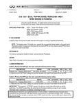
The ECU+ Fuel/Timing/Datalogging
Piggyback Engine Computer
Version 2.16 Upgrade Guide
Dec 21, 2011
Page 1
Table of Contents
1 Introduction............................................................................................................................................3
2 What's New............................................................................................................................................3
3 Hardware Requirements.........................................................................................................................3
4 Jumper Changes.....................................................................................................................................4
4.1 Removing and Opening the Silver Box..........................................................................................4
4.2 Jumper Positions.............................................................................................................................5
4.3 JP8, the OBD Disconnect Jumper..................................................................................................5
4.4 JP3, the OBD Mode Jumpers.........................................................................................................6
4.5 Reinstalling the Silver Box.............................................................................................................6
5 Installing the New ECU+ Software........................................................................................................7
6 Upgrading the DSP Firmware................................................................................................................7
7 Upgrading the AVR Firmware.............................................................................................................11
8 Wiring Changes....................................................................................................................................12
8.1 No Lift to Shift – The Clutch Switch Wire..................................................................................12
8.2 The External Switch.....................................................................................................................13
8.3 The Simulated Front O2 Output...................................................................................................13
8.4 The 1G DSM OBD Connections..................................................................................................13
8.5 Boost Control Connections...........................................................................................................13
9 Finishing Up.........................................................................................................................................13
10 Problems.............................................................................................................................................13
11 The Last Word....................................................................................................................................13
Page 2
1 Introduction
This upgrade guide describes what's new in the ECU+ firmware and software, version 2.16. Version
2.16 is a minor update to the ECU+ firmware and software that fixes a few bugs and enhances existing
features. This guide is everything you need to know to update to the new firmware and software.
2 What's New
The ECU+ firmware and software version 2.16 is a minor update to the ECU+. Improvements over
version 2.15 include:
●
Improved cam/crank signal replication during shifts. May fix “shift knock” when shifting.
●
Improved wideband-to-narrowband conversion algorithm to avoid “slow O2 sensor” checkengine codes.
●
Fixed anti-stall configuration dialog, which wasn't configuring the firmware correctly.
●
Files displayed via the Add Overlay menu option no longer added to the recent files list on the
File menu.
●
Implemented a recent overlay files list on the right-click (context) menu. This speeds up the
common case of overlaying a recently-added file.
●
Now support up to 10 overlays.
●
A variety of other overlay-related improvements.
●
Extended the Drag Race Analysis. Now displays selectable distance, speed or acceleration with
configurable smoothing.
●
Improved tooltip display for graphs.
●
Made graph smoothing much better for coarse values. Previously, things like ignition timing
(which has a 1 degree resolution) was only smoothable down to the whole number. Now, these
types of values smooth to a fractional value. Much better.
●
Added additional type of Auto-file naming. Now names can include a one-up count, for
generating filenames like Run1.ecd, Run2.ecd, etc.
A complete list of new features and links to some of the discussions of these features is available in the
ECU+ forums, at
http://www.ecuplus.com/forums/viewtopic.php?f=7&t=998
3 Hardware Requirements
The new version 2.16 firmware/software release requires the “silver box” ECU+ hardware, and will not
work on the “black box” units.
One set of changes was made during silver box production that introduced new hardware features, and
version 2.10 and up of the ECU+ firmware/software release begins to take advantage of these new
features. As such, there are two “types” of ECU+ silver boxes, and the type of box is determined by the
unit's serial number, which can be found on the Miscellaneous page of the ECU+ Win software's head
unit settings dialog.
●
Serial number 2000 through 2099. These are the original design of the silver box hardware.
●
Serial number 2100 and higher. These are the most recent design of the silver box hardware.
The original design (S/Ns 2000-2099) is missing a few hardware features that are available in the later
hardware. During 2007 and 2008 hardware upgrades were offered for a nominal fee that would bring
these older devices up to the specs of the most recent devices. If you have an upgraded original design
silver box, your unit includes all of the new functionality. Otherwise, you are out of luck as the
hardware upgrades are no longer offered.
When using version 2.15 (and up) of the ECU+ software and firmware, non-upgraded original design
ECU+'s will be missing the following functionality:
●
The no-lift-to-shift feature. This feature uses the clutch switch input, which isn't available on
the original design of the ECU+ silver box.
●
Gear calculation, which uses the clutch switch input to determine “no gear” times, may give
bogus gear values when the clutch is in.
●
The new drag analysis feature may not be able to calculate accurate shift times, as this also uses
the clutch switch input if available.
●
Fuel, timing and boost maps won't be switchable via an external switch. This external switch
input isn't available on the original design of the ECU+ silver box. Map switching is still
possible without this input, but the ECU+ won't be able to use an external stimulus to switch
maps.
4 Jumper Changes
Inside the silver box ECU+ are several “jumpers” (shorting blocks, which short two circuit board pins
together) that may need to be modified to get the ECU+ silver box to work with the version 2.10 and
higher firmware and hardware. Most cars won't need to alter the jumper settings, so read this section
completely before removing the ECU+ silver box from your car.
4.1 Removing and Opening the Silver Box
To inspect or alter the jumper settings of the ECU+ silver box circuit board, simply:
1. Remove the silver box from your car. Both the black (low current) and gray (high current)
connectors can be released from the silver box to aide removal. For the black connector,
“wiggle” it out underneath the “arms” that extend out of the silver box. (Some silver box
ECU+'s don't have arms.) For the gray connector, squeeze the tab on the top of the connector
and wiggle the connector free.
2. Remove the four end panel screws on each end of the box and remove both end panels.
3. Slide out the ECU+ circuit board from the box. Be very careful with this board, as static
electricity can destroy the board.
Page 4
4.2 Jumper Positions
Illustration 1 - Jumper locations
Illustration 1 Shows an ECU+ circuit board, and the locations of JP3 and JP8. These are the two
jumpers that may need to be modified.
4.3 JP8, the OBD Disconnect Jumper
Jumper JP8 (top right of the board) is the so-called OBD-II Disconnect jumper. On some of the ECU+
circuit boards with S/Ns of 2000-2099, this jumper is not shorted (connected) at the factory. To correct
this, simply jumper the two pins of JP8 together with the jumper plug that's “hanging” off of one of the
JP8 pins. A shorted JP8 is shown in Illustration 2 below.
Illustration 2 - Connecting JP8
This jumper was disconnected on ECU+'s that shipped with version 2.03 or earlier of the ECU+
Page 5
firmware and software. If you have a ECU+ with a serial number of 2100 or higher, or you have an
ECU+ in which the OBD-II functionality (2G DSMs and the EVOs) works, this jumper is set properly
and does not need to be changed.
4.4 JP3, the OBD Mode Jumpers
Jumper JP3 (top center of the board) is the so-called OBD Mode jumper. This set of three jumpers
swaps in the hardware necessary to allow the ECU+ 's OBD port to talk to your stock ECU for OBD-II
screens and MUT-II datalogging. Two jumper configurations are supported:
1. ALDL mode, used for the 1G DSMs.
2. OBD-II mode, used for the 2G DSMs and the EVOs.
All ECU+'s are shipped from the factory with the jumpers in the OBD-II mode position. Before version
2.10 of the ECU+ firmware and software, the ECU+ didn't support the 1G DSM mode of operation, so
OBD-II mode was always configured at the factory. Now that the ECU+ does support the 1G DSM
mode of operation, these jumpers must be changed for the 1G DSM owners.
If you have a 2G DSM or EVO stock ECU, no changes to these jumpers need to be made. If your stock
ECU is from a 1G DSM, you'll need to alter the JP3 jumper configuration to use ALDL mode. The
figures below illustrate the jumper configuration for the two modes.
Illustration 4 - JP3 jumpers in OBD-II mode (2G DSMs and the
EVOs)
4.5 Reinstalling the Silver Box
After verifying or altering the jumper settings, simply reverse the procedure outlined in the section
Removing and Opening the Silver Box on page 4 to reinstall the ECU+ in your car.
Page 6
5 Installing the New ECU+ Software
To upgrade your ECU+ Windows software to version 2.16 from any prior version, simply run the
Setup.exe file supplied and follow the prompts. The new GUI installer will guide you through the
installation. The new ECU+ software will be installed to the same directory as your existing ECU+
installation.
If you have an Evolution VIII or IX, and plan to use the ECU+ alongside the EcuFlash tool, be sure to
install the Alternate Windows Executables. All other customers can skip this step.
6 Upgrading the DSP Firmware
The ECU+ includes two microprocessors inside the silver box. The first microprocessor is the socalled “DSP” microprocessor. This microprocessor runs the engine and does the majority of the
datalogging. The ECU+ software installation includes updated versions of this firmware that must be
installed.
To upgrade the DSP firmware, execute the following steps:
1. Connect your laptop to your ECU+ silver box.
2. Turn on the ignition, but don't start the car.
3. Run the new ECU+ Win software by double-clicking its icon on your Windows desktop.
4. Use the Settings->Update Firmware->DSP Firmware menu item to start the graphical DSP
firmware update wizard. This wizard will save your current head unit settings to disk, upgrade
your firmware, and restore your settings. In most cases, this process is as simple as pressing
Next a few times. Always upgrade to the latest DSP firmware (this is the wizard's default), as
downgrading is not supported.
The firmware upgrade should complete without error. Some sample screenshots are shown below.
Page 7
Illustration 6 - Starting the DSP firmware update process
Page 8
Page 9
Page 10
7 Upgrading the AVR Firmware
The second microprocessor inside the silver box is the so-called “AVR” microprocessor. This
microprocessor talks to the OBD port on your stock ECU. The ECU+ software installation also
includes updated versions of this firmware that should be installed.
To upgrade the AVR firmware, execute the following steps:
1. Connect your laptop to your ECU+ silver box.
2. Turn on the ignition, but don't start the car.
5. Run the new ECU+ Win software by double-clicking its icon on your Windows desktop.
6. Use the Settings->Update Firmware->AVR Firmware menu item to start the graphical AVR
firmware update dialog box.
7. Use the Browse button to select an AVR firmware version appropriate for your car.
8. Press the Start button to begin the upgrade.
The firmware upgrade should complete without error. A sample screen is shown below.
Page 11
Illustration 10 - A sample run of the AVR firmware update
8 Wiring Changes
To take advantage of the new functionality in the ECU+ version 2.10 and higher firmware, some
changes to the ECU+ wiring may be required depending on your car type and ECU+ head unit serial
number. These wiring changes are all described in the ECU+ manual; this section points out what
changes are necessary for what functionality.
8.1 No Lift to Shift – The Clutch Switch Wire
To use the ECU+'s no-lift-to-shift (NLTS) function, a connection between the “top clutch switch” and
the ECU+ head unit is necessary. The clutch switch allows the ECU+ head unit to know when the
clutch is depressed, and thus when to activate NLTS.
As described in the section Hardware Requirements on page 3, this feature requires that ECU+ head
units with serial numbers of 2000-2099 be updated to match the hardware available in later units.
Assuming you have an updated or later version of the head unit, there are two cases:
1. 1990-1999 DSMs – the clutch switch wire must be wired up manually, independent of whether
or not you own a PnP ECU+.
2. 2003-2006 EVOs – the clutch switch wire is already wired for you on PnP ECU+'s, or must be
wired manually on wire-it-yourself ECU+'s.
The clutch switch wiring is described in section 5.5.8 of the ECU+ user's manual.
Page 12
8.2 The External Switch
As with the clutch switch input, this input is not available on ECU+'s with serial number 2000-2099
unless the hardware has been updated to match the hardware on later models of the silver box.
To external switch input is a 5 volt input that allows the ECU+ firmware to switch between two sets of
fuel and timing maps based on an external input. This input can come from a physical switch or the
output of a controller box (for nitrous, etc.). This always needs to be hand-wired on all ECU+'s.
The external switch wiring is described in section 5.5.9 of the ECU+ user's manual.
8.3 The Simulated Front O2 Output
The simulated front O2 output allows the ECU+ to generate a front O2 signal based upon the air/fuel
ratio calculated by an attached wideband O2 sensor kit. This must be hand-wired if you want to use
this feature.
The simulated front O2 wiring is described in section 5.5.7 of the ECU+ user's manual.
8.4 The 1G DSM OBD Connections
New in ECU+ firmware version 2.10 is support for the OBD connections on first generation (19901994) DSMs. Two wires must be newly-connected on these cars, as described in section 5.4.1 of the
ECU+ user's manual. Note that one of the connections is on the “high current” connector, which
previously only contained power connections.
8.5 Boost Control Connections
New in ECU+ firmware version 2.15 is support for boost control using a GM boost control solenoid.
Two new wires must be connected to the solenoid as described in section 5.5.11 of the ECU+ user's
manual.
9 Finishing Up
At this point, your hardware jumper settings are good-to-go, you have new firmware and software
installed, and you're ready to try out some of the new features in the ECU+. To see what kind of new
things are configurable, have a look at the main menu items Settings->ECU+ Win and Settings>ECU+ Head Unit. Also, please at least skim the ECU+ user's manual (now over 120 pages) for
things that are new. If you choose to use the no-lift-to-shift feature, map set switching with an external
switch or boost control, there is a bit of additional wiring that needs to be done. Most of the other
features are software/firmware-only, and just need to be configured.
10 Problems
If you have any problems with the upgrade to the ECU+ firmware or software, or if you find any bugs
in the software, send an e-mail to [email protected].
11 The Last Word
Version 2.16 of the ECU+ firmware and software version may be the final release for the silver box
ECU+, as the device is no longer being sold. Thanks to all of the folks who have supported the ECU+
over the years!
Page 13
Tom Collins
[email protected]
Page 14