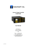
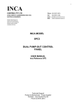
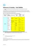
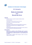
1
Copyright Notice Copyright Simon Brattel, 2005. All rights are reserved. Document Issue 1.0a (13 October 2005). Technical Support For software updates see www.scanwel.co.uk, for technical support contact [email protected] or telephone (44) 1678 530281 fax (44) 1678 521755. Trademarks All trademarks that may be contained within this publication are registered with their respective companies. Warranty Summary (DIGITEL SPC-2) Scanwel Ltd warrants that the products that it manufactures and sells will be free from defects in materials and workmanship for a period of one (1) year from the date of shipment from an authorised distributor. If a product proves defective within the respective period, Scanwel will provide repair or replacement as described in the complete warranty statement. To arrange for service or to obtain a copy of the complete warranty statement, please contact your nearest Scanwel distributor. EXCEPT AS PROVIDED IN THIS SUMMARY OR THE APPLICABLE WARRANTY STATEMENT, SCANWEL MAKES NO WARRANTY OF ANY KIND, EXPRESS OR IMPLIED, INCLUDING WITHOUT LIMITATION THE IMPLIED WARRANTIES OF MERCHANTABILITY AND FITNESS FOR A PARTICULAR PURPOSE. IN NO EVENT SHALL SCANWEL BE LIABLE FOR INDIRECT, SPECIAL OR CONSEQUENTIAL DAMAGES. SPC-2 Configuration Tool User’s Manual Page 1 Table of Contents CHAPTER 1 : GENERAL INFORMATION ........................................................................3 INTRODUCTION ........................................................................................................................3 CHAPTER 2 : PC CONFIGURATION TOOL ....................................................................4 CHAPTER 3 : PIN 12, CURRENT OR PRESSURE MONITOR....................................5 Voltage monitoring (pin 14) ............................................................................................6 Linear Current monitoring (pin 12) ................................................................................8 Logarithmic Current monitoring (pin 12).....................................................................10 Linear Pressure monitoring (pin 12)............................................................................12 Logarithmic Pressure monitoring (pin 12)..................................................................14 SPC-2 Configuration Tool User’s Manual Page 2 Chapter 1: General Information - Introduction Chapter 1 : General Information Introduction This document describes (very, very briefly) some aspects of the SPC-2 configuration utility. The PC configuration software can be downloaded from: http://www.scanwel.com/downloads.html or http://www.desdes.com/products/spc2/ Details of the required serial cable are provided in the help menu of this software. In lieu of documentation please feel free to contact me ([email protected]) for any help using this configuration tool. SPC-2 Configuration Tool User’s Manual Page 3 Chapter 2: PC Configuration tool - Introduction Chapter 2 : PC Configuration tool There are currently two configuration applications, one for the SPC-1 and one for the SPC-2, these applications are available from your distributor or can be downloaded from the Scanwel website (currently at www.scanwel.co.uk). Although this application is not necessary for normal use of the SPC power supply, it does extend the functionality of the SPC and allows the user to configure many aspects of the SPCs behaviour. This includes the ability to alter the current to pressure scale factor used to calculate the vacuum pressure from the ion pump voltage and current. It can be used to customise the range of voltages, currents, and ion pump sizes that the SPC reports to the user, as well as setting the mode and scale-factors for the current/pressure and voltage monitoring outputs. It can also be used to customise the protection limits for the ion pump and SPC supply, and also to configure some cosmetic features of the SPC, for example the number of digits and rounding mode of the numeric display. This document discusses some aspects of the SPC2 version, they may be identically presented in the SPC1 version or not present at all. The SPC1 has been superseded by the SPC2, which has improved hardware and more comprehensive firmware. SPC-2 Configuration Tool User’s Manual Page 4 Chapter 3: Pin 12, Current or Pressure Monitor - Introduction Chapter 3 : Pin 12, Current or Pressure Monitor This section describes the configuration options available for the analogue output monitoring on pin 12 of the misc. connector. This document assumes you are configuring an SPC2 which has firmware version 2.02 or greater. If your SPC2 does not you may be able to upgrade the firmware. Please contact us (using the help menu) for details. Firstly, connect the SPC2 to the PC and start the PC configuration tool. Before doing anything else you MUST use the “Read_EEROM” button to read the EEROM. This is important because the EEROM stores calibration values that are unique to the particular SPC, so they must not be overwritten by the default values. If you do overwrite them please contact us, we keep records of the calibration values for each SPC shipped. Then select the “Output Control” tab, and you should see the following screen: This tab allows you to configure three different aspects of the SPC. The voltage monitoring output on pin 14, the Setpoint Hysteresis and the current/pressure monitoring on pin 12. SPC-2 Configuration Tool User’s Manual Page 5 Chapter 3: Pin 12, Current or Pressure Monitor - Introduction Voltage monitoring (pin 14) Voltage monitoring is supported by all versions of the SPC firmware, and the only configuration option available for the voltage monitoring is the scale factor, or gain. The output is always linear so the voltage on pin 14 is directly proportional to the absolute value of the output voltage, provided that this monitoring output falls in the range zero to +10V. The SPC cannot output values outside this range. (Note that the voltage on pin 14 is always positive regardless of the output polarity of the SPC). To calculate the scale factor required for any given gain you need to understand the architecture of the SPC, at least in so far as how the monitoring outputs work: Conceptually the two analogue monitoring outputs can be thought of as being driven by software using 16-bit digital to analogue converters (DACs). Each DAC can only output positive voltages, in the range zero to +10V DC. During normal operation each DAC is periodically (several times a second) given a value in the range zero to 65535 and it produces a voltage which is directly proportional to that value, so the value zero (or less) would result in an output of zero volts, and the value 65535 (or more) would result in an output of ten volts. The actual voltages are subject to normal analogue errors and noise, of course, so there may be a ‘gain’ error of +-2% and an offset error of some tens of mV from these ideal figures. For the voltage monitor the value that the software gives the DAC is the measured output voltage of the SPC (in volts) multiplied by the Scale Factor set during the configuration process. To calculate the desired scale factor use the following equation: Scale Factor = (monitoring voltage in volts)*6.5535/(output voltage in kilo-volts) Before changing this value remember to click on the “Read_EEROM” button! The calculated Scale Factor is entered into the Voltage Monitoring “Scale Factor” edit box. (This edit box can be a pain to use, sometimes it is necessary to delete digits in order to enter new ones). Then to update the SPC click on the “Write_EEROM” button. Please remember to read the EEROM first, otherwise you will destroy the SPCs calibration data. The SPC output voltage is unsigned, so the scale factor is always a positive number. As a worked example, if we want the monitoring voltage to be 1V per KV of output, so that an output voltage of 1KV would result in a monitoring pin voltage of 1V, we would set a scale factor of 6.5535 (this is the default value). In some cases the SPC is used at comparatively low voltages, say 3.5KV, and so the analogue monitoring pin would output values up to 3.5V. If it was desired to make this higher, perhaps to increase the monitoring accuracy, then the scale factor could be increased. SPC-2 Configuration Tool User’s Manual Page 6 Chapter 3: Pin 12, Current or Pressure Monitor - Introduction As a worked example, if we want the monitoring voltage to be 10V when the output voltage was 4KV, then we would set a scale factor of 16.384 If the value calculated by the SPC is larger than 65535 then the DAC ‘clips’ at full scale and outputs a voltage of 10V. If the value calculated by the SPC is smaller than 0 (negative) then the DAC ‘clips’ at zero and outputs a voltage of 0V. This cannot happen in practice. SPC-2 Configuration Tool User’s Manual Page 7 Chapter 3: Pin 12, Current or Pressure Monitor - Introduction Linear Current monitoring (pin 12) Linear current monitoring is supported by all versions of the SPC firmware. Prior to version 2.02 it was the only option available for pin 12 and so the PC configuration utility will not allow any other option to be selected when working with early versions of the SPC2. Also, prior to version 2.02 the only option available was a single linear scale factor. After version 2.02 (inclusive) the pin can be set to linear and/or logarithmic reporting. To select current monitoring click on the “Monitor Current” radio button. This is not strictly necessary for versions before 2.02 as there is no other option. If it is visible make sure that the “Ln Scale Factor” is set to zero (0). If it is visible make sure that the “Output Offset” is set to zero (0). We will discuss this later. With linear monitoring the voltage on pin 12 is directly proportional to the absolute value of the output current, provided that this monitoring output falls in the range zero to +10V. The SPC cannot output values outside this range. (Note that the voltage on pin 12 is always positive regardless of the output polarity of the SPC). To calculate the scale factor required for any given gain you need to understand the architecture of the SPC, at least in so far as how the monitoring outputs work: Conceptually the two analogue monitoring outputs can be thought of as being driven by software using 16-bit digital to analogue converters (DACs). Each DAC can only output positive voltages, in the range zero to +10V DC. During normal operation each DAC is periodically (several times a second) given a value in the range zero to 65535 and it produces a voltage which is directly proportional to that value, so the value zero (or less) would result in an output of zero volts, and the value 65535 (or more) would result in an output of ten volts. The actual voltages are subject to normal analogue errors and noise, of course, so there may be a ‘gain’ error of +-2% and an offset error of some tens of mV from these ideal figures. For the linear current monitor the value that the software gives the DAC is the measured output current of the SPC (in amps) multiplied by the Scale Factor set during the configuration process. To calculate the desired scale factor use the following equation: Scale Factor = (monitoring voltage in volts)*6.5535/(output current in amps) Alternatively you can work in mA and use: Scale Factor = (monitoring voltage in volts)*6553.5/(output current in milli-amps) Before changing this value remember to click on the “Read_EEROM” button! SPC-2 Configuration Tool User’s Manual Page 8 Chapter 3: Pin 12, Current or Pressure Monitor - Introduction The calculated Scale Factor is entered into the “Linear Scale Factor” edit box. Then to update the SPC click on the “Write_EEROM” button. Please remember to read the EEROM first, otherwise you will destroy the SPCs calibration data. The SPC output voltage is unsigned, so the scale factor would normally be a positive number, but see the section below describing the output offset. As a worked example, if we want the monitoring voltage to be 1V per mA of output, so that an output current of 1mA would result in a monitoring pin voltage of 1V, we would set a scale factor of 6553.5 (because 1mA is 1/1000 of an amp). In most cases the SPC is used at much lower currents than this, so a higher scale factor would normally be desirable to show these more accurately. As a worked example, if we want the monitoring voltage to be 1V per uA of output, so that an output current of 1uA would result in a monitoring pin voltage of 1V, we would set a scale factor of 6553500 (because 1uA is 1/1000000 of an amp). If the value calculated by the SPC is larger than 65535 then the DAC ‘clips’ at full scale and outputs a voltage of 10V. If the value calculated by the SPC is smaller than 0 (negative) then the DAC ‘clips’ at zero and outputs a voltage of 0V. This cannot happen in practice. From firmware version 2.02 it is also possible to add an output offset voltage to this output. Normally this would be set to zero but it can be used, for example, to have the monitoring pin start at some other voltage to allow for non-linear isolation barriers. The actual output voltage is the calculated output voltage plus the offset voltage, but note that the voltage still cannot go below zero or exceed 10V, so using the offset option means you may have to reduce the available range of the output to compensate. Note also that from firmware version 2.02 it is possible to use a negative scale factor, so that the output voltage would decrease with increasing output current. To use this sensibly means that you would need to also set a significant output offset voltage, or the voltage would start at zero and stay at zero. SPC-2 Configuration Tool User’s Manual Page 9 Chapter 3: Pin 12, Current or Pressure Monitor - Introduction Logarithmic Current monitoring (pin 12) Logarithmic current monitoring is only supported from version 2.02 of the SPC firmware. To obtain updated firmware please contact your distributor. To select current monitoring click on the “Monitor Current” radio button. Make sure that the “Linear Scale Factor” is set to zero (0). With logarithmic monitoring the voltage on pin 12 is directly proportional to the natural logarithm of the absolute value of the output current, provided that this monitoring output falls in the range zero to +10V. The SPC cannot output values outside this range. (Note that the voltage on pin 12 is always positive regardless of the output polarity of the SPC). To calculate the scale factor required for any given gain you need to understand the architecture of the SPC, at least in so far as how the monitoring outputs work: Conceptually the two analogue monitoring outputs can be thought of as being driven by software using 16-bit digital to analogue converters (DACs). Each DAC can only output positive voltages, in the range zero to +10V DC. During normal operation each DAC is periodically (several times a second) given a value in the range zero to 65535 and it produces a voltage which is directly proportional to that value, so the value zero (or less) would result in an output of zero volts, and the value 65535 (or more) would result in an output of ten volts. The actual voltages are subject to normal analogue errors and noise, of course, so there may be a ‘gain’ error of +-2% and an offset error of some tens of mV from these ideal figures. For the logarithmic current monitor the value that the software gives the DAC is the natural logarithm of the measured output current of the SPC (in milli-amps) multiplied by the Ln Scale Factor set during the configuration process. However, calculating this scale factor is not as simple as it first seems. Since the output current is usually much lower than 1mA the log(e) value of the current is usually negative, so at first sight you might want to make the scale factor negative in order to make the monitoring output positive. But doing this would have the unexpected consequence that the lower the output current was the higher the monitoring voltage would become. Consider (remember the current is measured in mA, not in A): Log(e) of 15mA is 2.708 Log(e) of 1mA is 0 Log(e) of 1uA (0.001mA) is –6.9077 Log(e) of 0.01uA (0.00001mA) is –11.513 SPC-2 Configuration Tool User’s Manual Page 10 Chapter 3: Pin 12, Current or Pressure Monitor - Introduction So, in practice what is usually required is to combine a positive scale factor with an output voltage offset. The best way to approach this seems to be along the following lines: First, set the Output Offset field to 10V. This means that for large currents where the logarithm returns small numbers we will get outputs near to 10V. Then we need to choose the lowest current we wish to report, and arrange the scale factor so that this value will give an output of (-) 10V… The combined effect of the offset and the calculated value will be to give an output from the SPC that is zero volts for currents below our minimum value and which rises logarithmically towards 10V as the current increases. So, let’s go through a worked example. Suppose we are interested in knowing about currents of the order of 0.01uA and above. The log(e) of 0.01uA is log(e) 10-5(mA), or -11.513, so to scale this up to the DAC fullscale value of 65535 we would have to multiply this value (-11.513) by (65535/-11.513), which is –5692.3 However, if you used this value (-5692.3) as the “Ln Scale Factor”, with an offset of zero, you would have an output which gave low voltages for high currents and which increased in voltage as the current fell, until it reached 10V for currents of 0.01uA and below. So, if we negate this value, and set the “Ln Scale Factor” to 5692.3, but also set the output offset to 10V, then we have a more sensible output monitor where the voltage rises with increasing current. It would be zero for any current below 0.01uA and then rise logarithmically until reaching 10V for a current of 1mA (log(e) of 1mA is 0) Before changing these values remember to click on the “Read_EEROM” button! The calculated Scale Factor is entered into the “Ln Scale Factor” edit box. Then to update the SPC click on the “Write_EEROM” button. Please remember to read the EEROM first, otherwise you will destroy the SPCs calibration data. To help with this setup it is possible to send the SPC a false current value and see what output voltage this produces (using a voltmeter or ‘scope), so that the values can be experimented with to produce the desired result. To send a test value enter it in the test value edit box and click on the “Try Value” button. When you have finished please remember to click on the “Stop Test” button to return control to the real, measured, value. SPC-2 Configuration Tool User’s Manual Page 11 Chapter 3: Pin 12, Current or Pressure Monitor - Introduction Linear Pressure monitoring (pin 12) Pressure monitoring is only supported from version 2.02 of the SPC firmware. To obtain updated firmware please contact your distributor. To select pressure monitoring click on the “Monitor Pressure” radio button. This is only available for versions 2.02 and above. If it is visible make sure that the “Ln Scale Factor” is set to zero (0). If it is visible make sure that the “Output Offset” is set to zero (0). We will discuss this later. With linear monitoring the voltage on pin 12 is directly proportional to the absolute value of the measured pressure, provided that this monitoring output falls in the range zero to +10V. The SPC cannot output values outside this range. To calculate the scale factor required for any given gain you need to understand the architecture of the SPC, at least in so far as how the monitoring outputs work: Conceptually the two analogue monitoring outputs can be thought of as being driven by software using 16-bit digital to analogue converters (DACs). Each DAC can only output positive voltages, in the range zero to +10V DC. During normal operation each DAC is periodically (several times a second) given a value in the range zero to 65535 and it produces a voltage which is directly proportional to that value, so the value zero (or less) would result in an output of zero volts, and the value 65535 (or more) would result in an output of ten volts. The actual voltages are subject to normal analogue errors and noise, of course, so there may be a ‘gain’ error of +-2% and an offset error of some tens of mV from these ideal figures. For the linear pressure monitor the value that the software gives the DAC is the measured pump pressure (in Torr) multiplied by the Scale Factor set during the configuration process. To calculate the desired scale factor use the following equation: Scale Factor = (monitoring voltage in volts)*6553.5 / (pressure in Torr) Or alternatively: Scale Factor = (monitoring voltage in volts)*8716.16 / (pressure in mBar) Or alternatively: Scale Factor = (monitoring voltage in volts)* 871616 / (pressure in Pascals) Before changing this value remember to click on the “Read_EEROM” button! The calculated Scale Factor is entered into the “Linear Scale Factor” edit box. Then to update the SPC click on the “Write_EEROM” button. Please remember to read the EEROM first, otherwise you will destroy the SPCs calibration data. SPC-2 Configuration Tool User’s Manual Page 12 Chapter 3: Pin 12, Current or Pressure Monitor - Introduction As a worked example, if we want the monitoring voltage to be 1V per 10-6 Torr, so that a pressure of 10-6 Torr would result in a monitoring pin voltage of 1V, we would set a scale factor of 6,553,600,000 As a worked example, if we want the monitoring voltage to be 1V per 10-8 Torr, so that a pressure of 10-8 Torr would result in a monitoring pin voltage of 1V, we would set a scale factor of 655,360,000,000 As a worked example, if we want the monitoring voltage to be 1V per 10-6 mBar, so that a pressure of 10-6 mBar would result in a monitoring pin voltage of 1V, we would set a scale factor of 8,716,155,000 As a worked example, if we want the monitoring voltage to be 1V per 10-4 Pascal, so that a pressure of 10-4 Pascal would result in a monitoring pin voltage of 1V, we would set a scale factor of 8,716,155,000 If the value calculated by the SPC is larger than 65535 then the DAC ‘clips’ at full scale and outputs a voltage of 10V. If the value calculated by the SPC is smaller than 0 (negative) then the DAC ‘clips’ at zero and outputs a voltage of 0V. This cannot happen in practice. From firmware version 2.02 it is also possible to add an output offset voltage to this output. Normally this would be set to zero but it can be used, for example, to have the monitoring pin start at some other voltage to allow for non-linear isolation barriers. The actual output voltage is the calculated output voltage plus the offset voltage, but note that the voltage still cannot go below zero or exceed 10V, so using the offset option means you may have to reduce the available range of the output to compensate. Note also that from firmware version 2.02 it is possible to use a negative scale factor, so that the output voltage would decrease with increasing pressure. To use this sensibly means that you would need to also set a significant output offset voltage, or the voltage would start at zero and stay at zero. SPC-2 Configuration Tool User’s Manual Page 13 Chapter 3: Pin 12, Current or Pressure Monitor - Introduction Logarithmic Pressure monitoring (pin 12) Logarithmic pressure monitoring is only supported from version 2.02 of the SPC firmware. To obtain updated firmware please contact your distributor. To select pressure monitoring click on the “Monitor Pressure” radio button. Make sure that the “Linear Scale Factor” is set to zero (0). With logarithmic monitoring the voltage on pin 12 is directly proportional to the natural logarithm of the absolute value of the measured pump pressure (in Torr), provided that this monitoring output falls in the range zero to +10V. The SPC cannot output values outside this range. (Note that the voltage on pin 12 is always positive regardless of the output polarity of the SPC). To calculate the scale factor required for any given gain you need to understand the architecture of the SPC, at least in so far as how the monitoring outputs work: Conceptually the two analogue monitoring outputs can be thought of as being driven by software using 16-bit digital to analogue converters (DACs). Each DAC can only output positive voltages, in the range zero to +10V DC. During normal operation each DAC is periodically (several times a second) given a value in the range zero to 65535 and it produces a voltage which is directly proportional to that value, so the value zero (or less) would result in an output of zero volts, and the value 65535 (or more) would result in an output of ten volts. The actual voltages are subject to normal analogue errors and noise, of course, so there may be a ‘gain’ error of +-2% and an offset error of some tens of mV from these ideal figures. For the logarithmic pressure monitor the value that the software gives the DAC is the natural logarithm of the measured pump pressure (always in Torr) multiplied by the Ln Scale Factor set during the configuration process. However, calculating this scale factor is not as simple as it first seems. Since the pressure is always much lower than 1Torr the log(e) value of the pressure is always negative, so at first sight you might want to make the scale factor negative in order to make the monitoring output positive. But doing this would have the unexpected consequence that the lower the pressure the higher the monitoring voltage would become. Consider (remember the pressure is measured in Torr, regardless of the SPC display): Log(e) of 1e-4 is –9.2103 Log(e) of 1e-5 is –11.513 Log(e) of 1e-6 is –13.816 Log(e) of 1e-7 is –16.118 Log(e) of 1e-8 is –18.421 Log(e) of 1e-9 is –20.723 SPC-2 Configuration Tool User’s Manual Page 14 Chapter 3: Pin 12, Current or Pressure Monitor - Introduction Log(e) of 1e-10 is –23.026 Log(e) of 1e-11 is –25.329 So, in practice what is usually required is to combine a positive scale factor with an output voltage offset. The best way to approach this seems to be along the following lines: First, set the Output Offset field to 10V. This means that for high pressures where the logarithm returns small numbers we will get outputs near to 10V. Then we need to choose the lowest pressure we wish to report, and arrange the scale factor so that this value will give an output of (-) 10V… The combined effect of the offset and the calculated value will be to give an output from the SPC that is zero volts for pressures below our minimum value and which rises logarithmically towards 10V as the pressure increases. So, let’s go through a worked example. Suppose we are interested in knowing about pressures of the order of 1e-10Torr and above. The log(e) of 1e−10 is −23.026, so to scale this up to the DAC full-scale value of 65535 we would have to multiply this value (−23.026) by (65535/−23.026), which is −2846.13 However, if you used this value (−2846.13) as the “Ln Scale Factor”, with an offset of zero, you would have an output which gave low voltages for high pressures and which increased in voltage as the pressure fell, until it reached 10V for pressures of 1e−10 Torr and below. So, if we negate this value, and set the “Ln Scale Factor” to 2846.13, but also set the output offset to 10V, then we have a more sensible output monitor where the voltage rises with increasing pressure. It would be zero for any pressure below 1e−10 Torr and then rise logarithmically until reaching 10V for a pressure of 1 Torr. Of course, it would never reach 1Torr as the SPC can’t measure pressures that high. Before changing these values remember to click on the “Read_EEROM” button! The calculated Scale Factor is entered into the “Ln Scale Factor” edit box. Then to update the SPC click on the “Write_EEROM” button. Please remember to read the EEROM first, otherwise you will destroy the SPCs calibration data. To help with this setup it is possible to send the SPC a false pressure value and see what output voltage this produces (using a voltmeter or ‘scope), so that the values can be experimented with to produce the desired result. To send a test value enter it in the test value edit box and click on the “Try Value” button. When you have finished please remember to click on the “Stop Test” button to return control to the real, measured, value. The values are given in Torr, and the format “1e-10”, etc, can be used to enter small values. SPC-2 Configuration Tool User’s Manual Page 15