1
Technische Universität
Braunschweig
Institut für Datentechnik
und Kommunikationsnetze
GSEOS
User’s Manual
Revision 1.2
IDA-GSEOS-0001
June 2000
Prepared by
Kay-Uwe Reiche, Hagen Schmidt, Kai Stoeckner, Tim Wittrock
Institut für Datentechnik
und Kommunikationsnetze
TECHNISCHE UNIVERSITÄT
BRAUNSCHWEIG
Project:
GSEOS
Ref.:
GSEOS User’s Manual
IDA-GSEOS-0001
Issue: 1.2
Date: 6/5/2000
Page: 2
of:
48
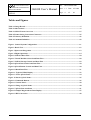
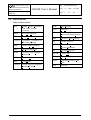
Tables and Figures ............................................................................................................................. 4
1
Scope............................................................................................................................................ 5
1.1 Purpose of this Document .................................................................................................................. 5
1.2 Change Record.................................................................................................................................... 5
1.3 Reference Documentation .................................................................................................................. 5
1.4 Abbreviations ...................................................................................................................................... 6
1.5 Key Word Definitions......................................................................................................................... 7
2
Introduction................................................................................................................................ 9
3
Overview ................................................................................................................................... 10
3.1 Inheritance......................................................................................................................................... 10
3.2 General System Configuration ........................................................................................................ 11
3.2.1 Bench Test (Assembly Level).................................................................................................... 12
3.2.2 Spacecraft Integration (System Level)....................................................................................... 13
3.2.3 Flight Operation (Mission Level) .............................................................................................. 14
4
Main Features........................................................................................................................... 15
4.1 Platform ............................................................................................................................................. 16
4.2 Tools ................................................................................................................................................... 16
4.2.1 Command Processor................................................................................................................... 17
4.2.2 Data Decoder.............................................................................................................................. 17
4.2.3 Data Display............................................................................................................................... 17
4.2.4 Data Monitoring......................................................................................................................... 17
4.2.5 Logging ...................................................................................................................................... 17
4.2.6 Recording/Playback ................................................................................................................... 17
4.2.7 Printing....................................................................................................................................... 18
4.2.8 Command Batch Files ................................................................................................................ 18
4.2.9 External Program Calls .............................................................................................................. 18
4.2.10 Network...................................................................................................................................... 18
4.2.11 Serial Ports ................................................................................................................................. 18
4.2.12 Special H/W Support ................................................................................................................. 18
5
System Architecture................................................................................................................. 20
6
Configuration ........................................................................................................................... 21
6.1 Overview ............................................................................................................................................ 21
6.2 Configuration Language vs. QLook................................................................................................ 21
6.3 The GSEOS Language...................................................................................................................... 23
6.3.1 Language Main Features ............................................................................................................ 23
6.3.1.1
6.3.1.2
6.3.1.3
6.3.1.4
6.3.2
6.3.3
Decoders............................................................................................................................................... 24
QLook Items......................................................................................................................................... 24
Commanding ........................................................................................................................................ 25
Batch Files............................................................................................................................................ 25
Language Example..................................................................................................................... 25
Data and Control Flow............................................................................................................... 28
Institut für Datentechnik
und Kommunikationsnetze
TECHNISCHE UNIVERSITÄT
BRAUNSCHWEIG
Project:
GSEOS
6.3.3.1
6.3.3.2
6.3.3.3
6.3.3.4
6.3.3.5
Ref.:
GSEOS User’s Manual
IDA-GSEOS-0001
Issue: 1.2
Date: 6/5/2000
Page: 3
of:
48
Virtual Machine.................................................................................................................................... 28
GSEOS Startup..................................................................................................................................... 29
QLook Items......................................................................................................................................... 29
QLook Buttons ..................................................................................................................................... 30
Batch Execution ................................................................................................................................... 31
6.4 QLook ................................................................................................................................................ 32
6.4.1 Navigation Tree.......................................................................................................................... 33
6.4.2 Data Display............................................................................................................................... 33
6.4.2.1
6.4.2.2
6.4.2.3
6.4.2.4
6.4.3
6.4.4
Active QLook Items ............................................................................................................................. 33
Passive QLook Items............................................................................................................................ 35
Command Buttons ................................................................................................................................ 36
Data Monitor ........................................................................................................................................ 36
Logging Display......................................................................................................................... 37
Configuration ............................................................................................................................. 37
6.4.4.1 General GSEOS Configuration ............................................................................................................ 37
6.4.4.2 Data Display Configuration.................................................................................................................. 38
7
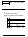
Configuration Example ........................................................................................................... 42
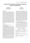
7.1 Experiment Description ................................................................................................................... 42
7.1.1 Telemetry Format....................................................................................................................... 42
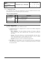
7.1.2 Command Format....................................................................................................................... 43
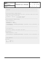
7.2 GSEOS Configuration...................................................................................................................... 43
7.2.1 Configuration File ...................................................................................................................... 44
7.2.2 Data Display............................................................................................................................... 47
Institut für Datentechnik
und Kommunikationsnetze
TECHNISCHE UNIVERSITÄT
BRAUNSCHWEIG
Project:
GSEOS
Ref.:
GSEOS User’s Manual
IDA-GSEOS-0001
Issue: 1.2
Date: 6/5/2000
Page: 4
of:
48
Tables and Figures
Table 1 Change Record ................................................................................................................................... 5
Table 2 Abbreviations ..................................................................................................................................... 6
Table 3 GSEOS Feature Overview .............................................................................................................. 15
Table 4 Format String Conversion Characters .......................................................................................... 35
Table 5 Telemetry Definition........................................................................................................................ 42
Table 6 Command Definition ....................................................................................................................... 43
Figure 1 General System Configuration...................................................................................................... 11
Figure 2 Bench Test ....................................................................................................................................... 12
Figure 3 Spacecraft Integration ................................................................................................................... 13
Figure 4 Flight Operations............................................................................................................................ 14
Figure 5 GSEOS 5 Data Flow ....................................................................................................................... 20
Figure 6 Virtual Machine Control and Data Flow ..................................................................................... 28
Figure 7 GSEOS Startup Control and Data Flow ...................................................................................... 29
Figure 8 QLook Item Control and Data Flow ............................................................................................ 30
Figure 9 QLook Button Control and Data Flow......................................................................................... 30
Figure 10 Batch Data Flow ........................................................................................................................... 31
Figure 11 Typical GSEOS Display ............................................................................................................... 32
Figure 12 Active QLook Items...................................................................................................................... 34
Figure 13 Passive QLook Items .................................................................................................................... 35
Figure 14 Command Buttons........................................................................................................................ 36
Figure 15 Control Panel ................................................................................................................................ 38
Figure 16 Sizing of QLook Items.................................................................................................................. 40
Figure 17 QLook Item Attributes ................................................................................................................ 41
Figure 18 Sample Magnetometer Data Display .......................................................................................... 47
Figure 19 H/K Conversion ............................................................................................................................ 48
Institut für Datentechnik
und Kommunikationsnetze
TECHNISCHE UNIVERSITÄT
BRAUNSCHWEIG
Ref.:
GSEOS User’s Manual
Project:
GSEOS
IDA-GSEOS-0001
Issue: 1.2
Date: 6/5/2000
Page: 5
of:
48
1 Scope
1.1 Purpose of this Document
Purpose of this document is to describe the main features and the internal structure of the IDA
GSEOS.
1.2 Change Record
Table 1 Change Record
Date
Revision
Author
Affected Sections
11/18/1999
1.0
HS, KS, KUR, TW All sections
1/13/2000
1.1
Stoeckner
3.2, 4.2, 4.2.5
6/5/2000
1.2
Stoeckner
minor spelling corrections
1.3 Reference Documentation
All GSEOS related documents are listed in the GSEOS Document Index IDA-GSEOS-0000.
Institut für Datentechnik
und Kommunikationsnetze
TECHNISCHE UNIVERSITÄT
BRAUNSCHWEIG
Ref.:
GSEOS User’s Manual
Project:
GSEOS
IDA-GSEOS-0001
Issue: 1.2
Date: 6/5/2000
Page: 6
of:
48
1.4 Abbreviations
Table 2 Abbreviations
APL
Applied Physics Laboratory
of the Johns Hopkins
University
H/K
Housekeeping
H/W
Hardware
BDM
Block Data Manager
IDA
Institut für
Datenverarbeitungsanlagen
CCS
Central Checkout System
IDL
Interactive Data Language
CCSDS Consultative Committee for
Space Data Systems
IP
Internet Protocol
DDE
Dynamic Data Exchange
MGSE
Mechanical Ground
Support Equipment
DPU
Data Processing Unit
PC
Personal Computer
EGSE
Electrical Ground Support
Equipment
QLook
Quick Look
EM
Electrical Model
S/C
Spacecraft
FM
Flight Model
SFDU
Standard Formatted Data
Units
S/W
Software
GSEOS Ground Support Equipment
Operating System
Institut für Datentechnik
und Kommunikationsnetze
TECHNISCHE UNIVERSITÄT
BRAUNSCHWEIG
Ref.:
GSEOS User’s Manual
Project:
GSEOS
IDA-GSEOS-0001
Issue: 1.2
Date: 6/5/2000
Page: 7
of:
48
1.5 Key Word Definitions
Active QLook Items
Visual part of the Data Display. An Active QLook Item displays
Block Elements in different formats (e.g. hex, decimal, array,
y(t)-plots, y(x)-plots, histogram, images) and is refreshed
automatically if the displayed Block Element has changed.
Batch Manager
GSEOS module, responsible for batch file handling (e.g. batch
start, suspend, resume, abort).
BDM
GSEOS module, responsible for data driven Block stream
handling.
Block
All data handled by the GSEOS is grouped in Blocks. (e.g.
telemetry data blocks). One Block contains one ore more Block
Elements. All Blocks are time tagged and are processed
(decoded, monitored, displayed etc.) in the order of their arrival.
Block Element
Part of a Block. Block Elements can be defined bit-precisely and
are accessible from the G-Language by their names.
Compiler
GSEOS module, responsible for compiling of the configuration
files written in the G-Language. The output of the Compiler is
the internal configuration of other GSEOS modules.
Control Panel
GSEOS module, responsible for general configuration.
Data Display
Visual part of QLook, responsible for the display of several
Active and Passive QLook Items. The Data Display is also the
interface of the built-in graphic editor for the QLook Item
configuration.
Decoder
Part of BDM, responsible for the data driven Block processing.
After arrival of a Block the Decoder module calls a user defined
decoder function for this special block type.
Edit Mode
Mode of the Data Display. In the Edit Mode interactive
modifications of QLook Items can be done.
G-Language
Configuration language of GSEOS. All GSEOS modules use the
same C-like language.
Logging Display
Part of QLook, responsible for displaying and storing of message
protocols.
Navigation Tree
Part of QLook, responsible for easy selection of a Data Display.
Operational Mode
Mode of the Data Display. In the Operational Mode no
interactive modifications of QLook Items can be done. This
prevents the less experienced user from the risk that the
Institut für Datentechnik
und Kommunikationsnetze
TECHNISCHE UNIVERSITÄT
BRAUNSCHWEIG
Project:
GSEOS
Ref.:
GSEOS User’s Manual
IDA-GSEOS-0001
Issue: 1.2
Date: 6/5/2000
Page: 8
of:
48
configuration is destroyed erroneously.
Passive QLook Items
Visual part of the Data Display. A Passive QLook Item displays
static elements (e.g. text, static pictures).
Property Sheet
Part of QLook. Property Sheets are special dialog boxes for
configuring QLook Item attributes or general setups.
QLook
GSEOS module, responsible for all display related GSEOS
tasks.
Recorder
GSEOS module, responsible for recording and playback of
Blocks.
Institut für Datentechnik
und Kommunikationsnetze
TECHNISCHE UNIVERSITÄT
BRAUNSCHWEIG
Project:
GSEOS
Ref.:
GSEOS User’s Manual
IDA-GSEOS-0001
Issue: 1.2
Date: 6/5/2000
Page: 9
of:
48
2 Introduction
This paper describes the main features and the internal structure of the IDA Ground Support
Equipment Operating System Version 5 (GSEOS 5). First it states the purposes of IDA
GSEOS and gives an overview of the software and hardware relationship. This is followed by
a general description of the software concepts. The last chapter shows the configuration of the
system.
A detailed description of the operating of the GSEOS program can be found in the GSEOS
Reference Manual (IDA-GSEOS-0002).
In the document GSEOS Language Description (IDA-GSEOS-0003) a full explanation of the
common configuration language of the GSEOS is given.
The GSEOS Language Runtime Library Description (IDA-GSEOS-0004) lists predefined
functions built in the GSEOS supporting for the development of user configuration.
Institut für Datentechnik
und Kommunikationsnetze
TECHNISCHE UNIVERSITÄT
BRAUNSCHWEIG
Ref.:
GSEOS User’s Manual
Project:
GSEOS
IDA-GSEOS-0001
Issue: 1.2
Date: 6/5/2000
Page: 10
of:
48
3 Overview
3.1 Inheritance
IDA developed the first version of the GSEOS during the 1980’s. It was realized that use of a
common checkout system would be a cost saving approach across the various projects. Due to
the easy integration of hardware into the PC, the test system GSEOS 1.0 was originally
developed for DOS based PC systems. It uses a simple character based interface for data
displays.
The work on GSEOS 2.0, that aimed at improved user and command interfaces as well as
recording capabilities, was preempted by the advent of the Windows graphical user interface
extension running on DOS. Development for GSEOS 2.0 was stopped and that for GSEOS
3.0 running on Windows 3.0 started.
On GSEOS 3.0 the data display capabilities have been drastically improved. They include
graphics in addition to the preceding text based displays. A recorder module was added as
well as support for monitoring the data. A simple decoder scripting language was
implemented that meets the most common decoding needs.
Up to version 3.3 the GSEOS supported more than 30 different space instruments, e.g.:
•
ACE: EPAM, SEPICA, SWICS, SWIMS, ULEIS
•
CASSINI: DISR, MAG
•
CLUSTER: RAPID
•
GALILEO: LRD, EPI
•
GEOTAIL: EPIC
•
SOHO: CELIAS, SUMER
•
Spaceshuttle: MAS
At the end of 1990’s engineers at APL started customer specific branch in the GSEOS history
tree. These efforts resulted in the GSEOS versions 3.4 (16 bit, Windows 3.0) and 4.0 (32 bit,
Windows 95/98). At that point the development at APL and IDA diverted. Currently APL
uses these own versions for the projects:
•
GALILEO, CASSINI, ACE, NEAR, IMAGE, TIMED, and SSUSI
As the system evolved over the years, new challenges appeared. First of all, technology has
moved on to 32-bit systems (Windows NT/2000), and support for 16-bit development
dropped. Second, the use of different syntax and scripting language for the different modules
made the system less consistent, and harder to document and configure. Furthermore the old
system has some disadvantages such as block size limitation at 64 Kbytes, commanding
(output data) throughput limited by timer interval (55 ms), and language deficiencies (e.g. no
loops).
Institut für Datentechnik
und Kommunikationsnetze
TECHNISCHE UNIVERSITÄT
BRAUNSCHWEIG
Ref.:
GSEOS User’s Manual
Project:
GSEOS
IDA-GSEOS-0001
Issue: 1.2
Date: 6/5/2000
Page: 11
of:
48
Responding to these challenges IDA started the development of the completely new GSEOS
version 5.0 in January 1998. To have the possibility to create optimum software architecture
without compatibility restrictions, the implementation started from scratch. There is no source
code used from previous GSEOS versions. Currently the GSEOS 5.0 is used for the projects:
•
ROSETTA: ROSINA, OSIRIS
•
MSRS: DSU
•
SMART: SIR
•
RTMC-3: IDA Test Equipment for High Capacity Memories
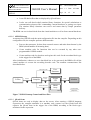
3.2 General System Configuration
During the development of scientific space experiments, sophisticated test equipment is
needed to operate the instrument and its various operational modes and to format the data
received from the instrument to an easily interpretable extract. In particular a S/C simulator is
used to simulate the electrical interfaces between the experiment DPU and the S/C data and
power system.
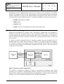
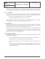
A computer, which is connected to the S/C simulator, transmits control commands to the S/C
simulator and receives DPU data from the S/C simulator. The whole arrangement (computer,
S/C simulator, external Power Supply, Harness, and operational S/W package, here GSEOS)
is referred as the Electrical Ground Support Equipment (EGSE). Figure 1 shows the general
configuration of the EGSE.
Data
Instrument
H/W
Commands
Power
Data
Spacecraft
Simulator
GSEOS
Commands
EGSE PC
Power
Supply
EGSE
Figure 1 General System Configuration
The GSEOS is designed to support all stages of experiment development, from bench
checking up to “quick-look” during flight operation. Using the same test system for the whole
lifetime of the instrument avoids fragmentation and duplication of efforts, which would result
in higher costs, more schedule and technical risk, and reduced capability.
Institut für Datentechnik
und Kommunikationsnetze
TECHNISCHE UNIVERSITÄT
BRAUNSCHWEIG
Ref.:
GSEOS User’s Manual
Project:
GSEOS
IDA-GSEOS-0001
Issue: 1.2
Date: 6/5/2000
Page: 12
of:
48
There are typically 3 phases during experiment development:
•
Bench Test (Assembly Level)
•
Spacecraft Integration (System Level)
•
Flight Operation (Mission Level)
The same EGSE hardware and software configuration can be used for all of these phases.
However, some hardware and software modules will be useful for only a single phase (e.g.
basic tests at mission level).
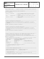
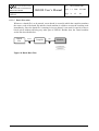
3.2.1 Bench Test (Assembly Level)
Sensor Data
Sensor Cmds.
Instrument
H/W
(Sensor)
Sensor Data
Sensor Cmds.
Power
Instrument
H/W
(DPU)
Sensor
Simulator
Telemetry
Commands
Power
Simulator Ctrl.
Telemetry
Spacecraft
Simulator
GSEOS
Commands
Simulator Ctrl.
EGSE PC
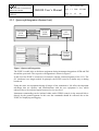
Figure 2 Bench Test
During the instrument development the EGSE is used as bench checkout equipment for EM
and FM tests, including sensor calibration.
For this application the GSEOS S/W running on the EGSE PC communicates with a project
specific S/C simulator H/W. The S/C Simulator emulates spacecraft command and telemetry
handling and power supply. The GSEOS controls the S/C simulator and is responsible for data
and command handling, both in real-time. Other GSEOS modules, as displaying, recording,
decoding, logging, and data printing support an efficient execution of all tests in the course of
the DPU/instrument development phase.
In particular, commands can be activated by clicking of a respective command button,
command strings can be generated and activated directly via buttons or dependent on
conditions, e.g. derived from sensitive H/K values or other specific values within the
scientific data flow.
The data response of the instrument DPU is decoded and displayed in selectable windows in
easily configurable representations as alphanumerical, bar graph, plot, etc., and recorded in an
easily retrievable way.
Sensor simulators are used to feed well-defined stimuli into the front electronics of the sensor.
Again, the sensor simulators are controlled by the GSEOS.
Institut für Datentechnik
und Kommunikationsnetze
TECHNISCHE UNIVERSITÄT
BRAUNSCHWEIG
Ref.:
GSEOS User’s Manual
Project:
GSEOS
IDA-GSEOS-0001
Issue: 1.2
Date: 6/5/2000
Page: 13
of:
48
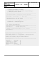
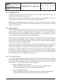
3.2.2 Spacecraft Integration (System Level)
Instrument
H/W
(Sensor)
Sensor Data
Instrument
H/W
(DPU)
Sensor Cmds.
Power
Telemetry
Commands
Power
S/C
System
S/C
Sensor
Simulator
Simulator Ctrl.
Telemetry
Spacecraft
Simulator
GSEOS
Commands
Network
Ground
Segment
(CCS)
Simulator Ctrl.
EGSE PC
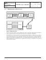
Figure 3 Spacecraft Integration
The EGSE is usable also as checkout equipment during instrument integration of EM and FM
aboard the spacecraft. The respective configuration is shown in Figure 3.
In this level the EGSE is connected via network with the Ground Segment of the CCS. The
S/C simulator is no longer needed. In principle, the EGSE is used in a similar way as during
bench test.
Using the same test equipment during all stages of the instrument’s life offers the important
advantage that no expertise and familiarization with the test equipment is lost, which
otherwise has to be acquired again from test level to test level.
Instrument commanding can be initiated either under GSEOS control via the network link or
directly by the ground segment. In this case the commands should be reflected also to the
EGSE, for displaying and logging.
Institut für Datentechnik
und Kommunikationsnetze
TECHNISCHE UNIVERSITÄT
BRAUNSCHWEIG
Ref.:
GSEOS User’s Manual
Project:
GSEOS
IDA-GSEOS-0001
Issue: 1.2
Date: 6/5/2000
Page: 14
of:
48
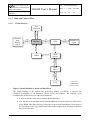
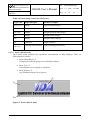
3.2.3 Flight Operation (Mission Level)
Instrument
H/W
(Sensor)
Sensor Data
Sensor Cmds.
Power
Instrument
H/W
(DPU)
Telemetry
Commands
Power
S/C
System
S/C
Sensor
Simulator
Simulator Ctrl.
Telemetry
Spacecraft
Simulator
GSEOS
Commands
Network
Simulator Ctrl.
Ground
Segment
(CCS)
EGSE PC
Figure 4 Flight Operations
The last experiment phase is the operation after launch. During the flight phase the EGSE is
used as a quick look tool, in principal in the same way as during S/C integration.
The EGSE PC provides an interface to the ground segment computer, which processes all data
received from spacecraft. This is typically a network connection to the CCS ground segment,
similar to that used in the integration phase. The ground segment delivers telemetry data, S/C
status data and reflects command data. If supported by the project commands can be initiated
from the EGSE, directly.
Institut für Datentechnik
und Kommunikationsnetze
TECHNISCHE UNIVERSITÄT
BRAUNSCHWEIG
Ref.:
GSEOS User’s Manual
Project:
GSEOS
IDA-GSEOS-0001
Issue: 1.2
Date: 6/5/2000
Page: 15
of:
48
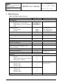
4 Main Features
Table 3 GSEOS Feature Overview
Feature
Performance
Data throughput
Input data (e.g. sensor data)
Output data (e.g. sensor command
data)
Response times
H/W interrupt
Decoder
Size limitation
Simultaneous execution of several batches
Task management
BDM buffer size allocation
Configuration
On-line configurable
GSEOS 3.3 compatible
Same configuration language for all
GSEOS modules
Syntax of configuration language
Nested block structure
System configuration dialogs
Platform
H/W
Intel PC
Alpha, MIPS (Windows NT/2000)
Multiprocessor support
If no specific H/W support is needed
Windows 98
Windows NT
Windows 2000
If H/W support is needed (e. g. Sensor I/F)
Windows 98
Windows NT
Windows 2000
Plug & Play support
GSEOS 5
Comment
@ 2 x PII-350
400 MBits/sec.
400 MBits/sec.
<10 µs
<5 ms
4 GByte
ü
event driven
@ 2 x PII-350
hard coded in driver
user configurable
per block
Windows NT based
dynamic
ü
–
ü
C
ü
ü
with minor modifications
to simplify task specific
configuration
ü
ü
ü
ü
ü
ü
Windows 2000 is next
generation O/S
–
ü
ü
ü
necessary for PCI-H/W
Institut für Datentechnik
und Kommunikationsnetze
TECHNISCHE UNIVERSITÄT
BRAUNSCHWEIG
Ref.:
GSEOS User’s Manual
Project:
GSEOS
IDA-GSEOS-0001
Issue: 1.2
Date: 6/5/2000
Page: 16
of:
48
4.1 Platform
The GSEOS runs within the Windows NT environment (currently versions NT 4.0 and
NT 2000) on INTEL PCs (optional ALPHA Workstation).
The INTEL platform is extremely cost effective and widespread. On PCs specific hardware
easily can be developed, built and integrated into the system. For installation and maintenance
expert knowledge is not required.
To increase the data throughput the GSEOS fully supports multiprocessor systems. The
GSEOS program contains several threads, which are separate program paths running in
parallel. The data throughput is nearly proportional to the number of processors used.
The operating system Windows NT is also available for other platforms than for INTEL PCs
such as workstations based on the ALPHA processor. Because all parts of the GSEOS are
coded in C++ (except a few lines of Assembler code), the GSEOS and its hardware driver are
portable to this platform.
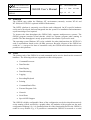
4.2 Tools
The primary task of the GSEOS is to send commands and to receive data from the connected
hardware. The following tools are supported to achieve this purpose:
•
Command Processor
•
Data Decoder
•
Data Display
•
Data Monitoring
•
Logging
•
Recording/Playback
•
Printing
•
Command Batch Files
•
External Program Calls
•
Network
•
Serial Ports
•
Special H/W Support
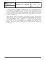
The GSEOS is highly configurable. Most of the configuration can be developed interactively
on the running system, assisted by a graphic editor. All modules of the program use the same
configuration language. So, it is guaranteed that all of the functionality built in the GSEOS is
usable in every module. E.g., it is possible to command the GSEOS via network or a serial
Institut für Datentechnik
und Kommunikationsnetze
TECHNISCHE UNIVERSITÄT
BRAUNSCHWEIG
Ref.:
GSEOS User’s Manual
Project:
GSEOS
IDA-GSEOS-0001
Issue: 1.2
Date: 6/5/2000
Page: 17
of:
48
communication port in the same way as the user is doing it by clicking a command button.
Chapter 6 describes the configuration in more detail.
4.2.1 Command Processor
At any time it is possible to send experiment commands and simulator commands directly to
the H/W or via network. The commands are activated by touching a button on the Data
Display or are executed time tagged or event driven. It is possible to define a command
database. All commands may have parameters. Mathematical expressions as parameter are
fully supported.
4.2.2 Data Decoder
Experiment data is grouped into blocks (e.g. Science Data, Housekeeping Data). Blocks are
user-defined structures on bit level. The data blocks and the elements inside the block can be
accessed by symbolic names. In contrast to the previous GSEOS versions, there are no
restrictions for the nesting depth of elements within the block structure.
Data processing in the GSEOS is data driven. After arrival of a data block the Decoder
module calls a user defined decoder function for this special block type. Inside this decoder
function all data processing takes place. The data may be rearranged as new blocks (e.g. sub-/
super-commutation) or commands are sent (e.g. simulation of sensor response).
4.2.3 Data Display
Both experiment and simulator data can be displayed as QLook Items on the Data Display in
selectable formats (hex, decimal, text, bitmap, histogram, plot y(t), plot y(x), etc.). The QLook
Items are displayed in different Data Displays organized as tree. The count of Data Display is
practically unlimited.
4.2.4 Data Monitoring
QLook Items can be checked automatically. Exceeding of a limit activates user defined
actions (e.g. switch power supply off, print error log). Monitoring is applicable to all data
known by the GSEOS.
4.2.5 Logging
Storage of command, data, and status protocols on the disk drive is supported. The protocol
may also be send to a printer.
4.2.6 Recording/Playback
All incoming and outgoing data can be stored to and played back from disk drive. There are
several modes for data replay (backward, forward, single step, continuous, seek). A Recorder
Database Manager shows information about the recorded data (e.g. recorder session name,
Institut für Datentechnik
und Kommunikationsnetze
TECHNISCHE UNIVERSITÄT
BRAUNSCHWEIG
Ref.:
GSEOS User’s Manual
Project:
GSEOS
IDA-GSEOS-0001
Issue: 1.2
Date: 6/5/2000
Page: 18
of:
48
recorded block names, start/end time). Any file oriented mass storage device is supported (e.g.
hard disk, magneto-optical disk, network drive).
4.2.7 Printing
All displayed data can be printed as a hardcopy of a GSEOS Data Display on a graphic (color)
printer. Printing of logging files is supported. It is possible to customize the printed page
layout (user-defined header and footer, time, date).
4.2.8 Command Batch Files
The GSEOS supports command batch files. Batches are useful for automatic test procedures.
Commands can be activated either time-triggered or event-driven. The GSEOS is able to run
several batches simultaneously and independently. This feature is useful to generate sequences
of test data independent of and asynchronous to the operation of the unit under test. A user
controlled Batch Manager is capable to suspend, resume, and abort running batches. For
synchronization of the several batches special commands are foreseen. Together with
monitoring and data logging automatic system tests can be run without any user supervision.
4.2.9 External Program Calls
External program calls including parameters and DDE are supported (e.g. call IDL interpreter
to process data, call Microsoft EXCEL for use of its data display functionality).
4.2.10 Network
The GSEOS PC can be connected to the network on IP level. The full program functions are
accessible via network (e.g. data transfer to other Ethernet user, remote commanding). The
GSEOS supports both client and server mode of communication. Special communication
protocols (e.g. CCSDS, SFDU) are implemented as data decoder functions.
4.2.11 Serial Ports
Up to 255 serial communication ports are supported by the GSEOS. Like a network
connection a serial connection can exploit all program functions. Data decoder functions are
used to decode the communication protocol. Further there are special functions to control the
handshake signals.
4.2.12 Special H/W Support
To access special H/W (e.g. spacecraft and sensor simulators) the GSEOS uses a Windows
NT kernel mode driver. After data has passed the driver it is available as data blocks for
further processing by the GSEOS.
This special driver is necessary because under Windows NT there is no way to access H/W
directly from a user program. The driver is responsible to the lowest-level handling of data
and commands and serves the interrupts of the special H/W. This driver is highly hardware
Institut für Datentechnik
und Kommunikationsnetze
TECHNISCHE UNIVERSITÄT
BRAUNSCHWEIG
Project:
GSEOS
Ref.:
GSEOS User’s Manual
IDA-GSEOS-0001
Issue: 1.2
Date: 6/5/2000
Page: 19
of:
48
dependent and therefore has to be adapted to the dedicated experiment H/W used inside the
PC. In EGSEs configured by IDA this adaptation is built-in.
Parallel
Service
Sound
Service
Parallel I/F
Speaker
Figure 5 GSEOS 5 Data Flow
Playback
Ext. Prog.
Call
Decoder
Configuration
Files
G-Compiler
Command & Batch
Processor
BDM
Queue
Near Realtime
BDM
Modules configured
by the G-Compiler
GSEOS
EGSE PC
Project:
Standard PC H/W
Ref.:
Windows NT
Printer
Mouse
Keyboard
Monitor
GSEOS User’s Manual
Recorder
GSEOS
Record
QLook
Data
Monitor
Print
Command
Display
Interaction
TECHNISCHE UNIVERSITÄT
BRAUNSCHWEIG
Message
Logging
Serial
Service
H/W
Service
Serial I/F
H/W
Driver
Network
Service
Test
H/W
Network I/F
Experiment
H/W
Realtime
Institut für Datentechnik
und Kommunikationsnetze
IDA-GSEOS-0001
Issue: 1.2
Date: 6/5/2000
Page: 20
of:
48
5 System Architecture
The next picture shows the main modules of the GSEOS and the data flow inside the EGSE
PC.
Institut für Datentechnik
und Kommunikationsnetze
TECHNISCHE UNIVERSITÄT
BRAUNSCHWEIG
Ref.:
GSEOS User’s Manual
Project:
GSEOS
IDA-GSEOS-0001
Issue: 1.2
Date: 6/5/2000
Page: 21
of:
48
6 Configuration
6.1 Overview
The GSEOS can be switched to one of two modes. In the Edit Mode interactive modifications
of parameters are supported. Data Displays can be defined interactively. In the Operational
Mode no modifications can be done interactively. This prevents the less experienced user
from the risk that the configuration is destroyed erroneously. So, the operation of the system
becomes very stable and robust.
The user should be somewhat familiar with the basics of the Windows NT graphical user
interface. At least the following basic procedures are needed to operate the GSEOS:
•
Using Keyboard and Mouse
•
Logging On as Windows NT User
•
Starting Applications
•
Moving and Sizing Windows
•
Using Dialog Boxes
•
Using On Line Help
These basic procedures are not explained here. If the user is new to using a graphical user
interface such as Windows NT, please refer to the “Microsoft Windows NT System Guide”
chapter 1 “Introducing Windows NT” and chapter 2 “Windows NT Basics”. Also a good
source of basic information is the Windows NT build in online help found in the menu
“Start à Help”.
6.2 Configuration Language vs. QLook
The GSEOS is designed to support the development, test and operating of a variety of S/C
instruments. Therefore a high flexibility of the configuration is needed. The GSEOS S/W can
be configured to a wide extend. There are two main tasks of configuration:
•
basic system configuration (with the configuration language)
− block definition
− data decoder definition
− function definition
•
interactive configuration of the user interface (with QLook)
− creation and configuration of Data Displays
− general program settings
Institut für Datentechnik
und Kommunikationsnetze
TECHNISCHE UNIVERSITÄT
BRAUNSCHWEIG
Project:
GSEOS
Ref.:
GSEOS User’s Manual
IDA-GSEOS-0001
Issue: 1.2
Date: 6/5/2000
Page: 22
of:
48
To provide a maximum of flexibility and performance the basic system configuration will be
done using a built-in compiler. This compiler use a special configuration language based on C
as input. The configuration files handled by the compiler contain all block definitions, the
processing of blocks (decoder) and all command functions as G-Language program (section
6.3. will describe the using of this language). Normally the GSEOS will be delivered with preconfigured G-Language files.
The user interface can be configured with the QLook module interactively. The name QLook
(Quick Look) describes the meaning of the module. The processed data can be viewed in Data
Displays quickly and easy without knowing the GSEOS language in detail. All configuration
work of the Data Displays can be done with a built in graphical editor with sparse mouse
clicks. Thereby the user can choose from a wide selection of formats the data can be
displayed: various numeric and graphical displays are available (section 6.4 will describe the
QLook module).
Institut für Datentechnik
und Kommunikationsnetze
Ref.:
TECHNISCHE UNIVERSITÄT
BRAUNSCHWEIG
GSEOS User’s Manual
Project:
GSEOS
IDA-GSEOS-0001
Issue: 1.2
Date: 6/5/2000
Page: 23
of:
48
6.3 The GSEOS Language
All processing of incoming data for displaying and decoding purposes is done by a virtual
machine. This machine is programmable through the GSEOS Language, which is based on C
and enhanced in some properties.
The machine is used for the following purposes:
•
Build an interface between QLook and the hardware drivers. Therefore it
− processes all QLook Items,
− translates numeric data into readable colored text and
− sends commands.
•
Decode data blocks, create and send new data blocks.
•
Run batch files.
The GSEOS Language (called G) allows a structured programming of the virtual machine and
also specifies the data structure of all data blocks handled by the BDM. The language provides
easy access to bit-precisely placed data block elements. Programs written in G are compiled
into special code that will be executed by the virtual machine.
Since all data processing is based on this freely programmable machine, the user is able to
configure nearly all parts of GSEOS exactly for his own needs with a common language. It is
not necessary to modify the GSEOS program code itself.
6.3.1 Language Main Features
As already mentioned, the GSEOS Language G is based on C. This means that the user can
•
define and access complex data structures (structure, union, array),
•
use different loops (for..., while..., do...while),
•
call functions with parameters (once declared, a function can be called from any
other program code like decoder, QLook Item, batch file...) and
•
use conditional executions (if...then...else..., switch...case...).
Nesting is unlimited. Some modifications have been introduced to eliminate sources potential
of error and to allow easy access to bit-precisely packed data that are created by external
sources:
•
No pointers
possible).
•
No global variables.
(instead C++-like referencing of parameters in function calls is
Institut für Datentechnik
und Kommunikationsnetze
TECHNISCHE UNIVERSITÄT
BRAUNSCHWEIG
Ref.:
GSEOS User’s Manual
Project:
GSEOS
IDA-GSEOS-0001
Issue: 1.2
Date: 6/5/2000
Page: 24
of:
48
•
No explicit typecasting of complex types (but slightly more tolerant in mixing types
of the same size).
•
Full runtime checking of array ranges, even of arrays with unknown size at compile
time. This prevents GSEOS to crash because of invalid memory accesses. Built in
error recovery allows to continue execution in most cases. Error recovery can be
limited to stop functions that are producing too many errors.
•
Automated interaction with the BDM:
− Bit-precise definition of the data structure and endian of blocks generated by
external hardware.
− Automatic conversion of bit-precise to byte based formats on read-access and
vice versa.
− Automatic conversion between Motorola data formats and Intel (big/little
endian).
− Built-in commands for triggering execution on incoming data blocks.
Since all data manipulations as well as commanding and displaying are programmable
through G, GSEOS allows easy, powerful and comfortable programming of nearly all userspecific parts.
The QLook-independent configuration (like definition of data block types, decoders and
global functions) can be done inside of one common configuration file But it is also possible
to split this file into several handy pieces and use the '#include' command to combine the parts
at compile time.
6.3.1.1 Decoders
User defined decoder functions are executed automatically by the BDM each time when a
user-specified data block arrives (generated by the hardware or internal sources). Each
decoder function can be allotted to a specific data block (or even a list of blocks). It is
possible also to allot several decoders to the same block.
Decoder functions can be used to create new blocks out of the incoming blocks; they can filter
data or combine multiple data blocks to one. It is possible to apply multiple decoder runs to
each incoming data block.
6.3.1.2 QLook Items
All data displayed by QLook is specified by G-expressions. Whenever the BDM processes a
new block of a type used inside the expression, the value is recalculated and displayed
automatically. The GSEOS Language support to translate numeric values into different
colored texts (to highlight alarm flags, for example). It is very simple to view only special
block elements - just specify the desired element like a part of a data structure inside the
GSEOS Language expression.
Institut für Datentechnik
und Kommunikationsnetze
TECHNISCHE UNIVERSITÄT
BRAUNSCHWEIG
Project:
GSEOS
Ref.:
GSEOS User’s Manual
IDA-GSEOS-0001
Issue: 1.2
Date: 6/5/2000
Page: 25
of:
48
The program code of QLook Items can be changed at runtime. In that case, the new program
will be compiled and the resulting code will be linked to the BDM instead of the former code.
6.3.1.3 Commanding
The hardware can be commanded by generating control sequences through GSEOS Language
and sending it to the hardware by calling runtime library functions. Commanding can be done
•
interactively by linking the program code to a QLook button or
•
program controlled inside of batch files or even decoders.
If the program code is linked to a QLook button it is recompiled immediately after a change.
The resulting code will be executed every time the button is pressed.
6.3.1.4 Batch Files
GSEOS Language is also used to write batch files that can run asynchronous. Waiting on
block arrival can be used to synchronize batch processes on special events. It is also possible
to suspend the execution of a batch file for a specified time interval.
Whenever a batch file is started, it is read and compiled. If no error occurs, the execution of
the resulting code is started immediately. The code will run once and is deleted after the
execution has finished. Each batch program runs in its own thread, so waiting in one batch
won't affect the execution of other GSEOS tasks.
6.3.2 Language Example
The following example demonstrates the use of G for data processing. It could be a part of the
initialization file and defines
•
a simple data block type that is used for receiving temperature and CPU-load data,
•
a block type that is used to transfer processed data to the display,
•
a decoder that calculates the average values of the last 10 values sent by sub-device 2
and
•
a text reference function that translates the temperature values into different named
ranges. QLook Items can use this function to display highlighted text if the optimum
temperature range is left.
Institut für Datentechnik
und Kommunikationsnetze
TECHNISCHE UNIVERSITÄT
BRAUNSCHWEIG
Ref.:
GSEOS User’s Manual
Project:
GSEOS
#define SAMPLE_COUNT 10
IDA-GSEOS-0001
Issue: 1.2
Date: 6/5/2000
Page: 26
of:
48
// number of samples to take for average calculation
//----------------------------------------------------------------------------// define a simple structure for data transmission
//----------------------------------------------------------------------------struct strTelemetry
{
char(3,0) cDeviceID;
// ID of subdevice sending this data (in data
// blocks: 3 valid bits, no gap to the next
// element)
long
lTemperature;
// current temperature of this device (32 valid
// bits, no gap)
short(14) sLoad;
// current processor load (in data blocks: 14
// valid bits)
};
//----------------------------------------------------------------------------// define a blocktype for incoming data.
// The blocktype with a data structure defined in strTelemetry is called
// tblkTeleIn. Any block of this type sent to the BDM will be accessible as
// _blkTeleIn.
//----------------------------------------------------------------------------blockdef strTelemetry tblkTeleIn _blkTeleIn;
//----------------------------------------------------------------------------// define a blocktype for processed average data.
// The blocktype with a data structure defined in strTelemetry is called
// tblkTeleAv. Any block of this type sent to the BDM will be accessible as
// _blkTeleAv.
//----------------------------------------------------------------------------blockdef strTelemetry tblkTeleAv _blkTeleAv;
//----------------------------------------------------------------------------// define a decoder that samples the last SAMPLE_COUNT telemetry data and
// calculates the average temperature and load of these samples.
// The calculated average is incorrect for the first SAMPLE_COUNT-1 runs.
//----------------------------------------------------------------------------decode on (_blkTeleIn)
{
static unsigned long ulCurrentIndex = 0;
// position for storing of values
// define arrays for storing the sampled temperature and load data
static long
lTemperatures[SAMPLE_COUNT];
static short
sLoads[SAMPLE_COUNT];
long
lAvTemperature = 0;
// average temperature
short
sAvLoad = 0;
// average processor load
unsigned long
ulCount;
tblkTeleAv
blkAverage;
// block containing the average
// process only blocks that are sent by device 2
if (_blkTeleIn.cDeviceID != 0b010)
return;
//--------------------------------------------------------------------------// store current temperature and load
//--------------------------------------------------------------------------lTemperatures[ulCurrentIndex] = _blkTeleIn.lTemperature;
sLoads[ulCurrentIndex]
= _blkTeleIn.sLoad;
//--------------------------------------------------------------------------// check temperature.
// temperature too high - send 'shut down' command and inform user
//--------------------------------------------------------------------------if (_blkTeleIn.lTemperature > 100000000)
Institut für Datentechnik
und Kommunikationsnetze
TECHNISCHE UNIVERSITÄT
BRAUNSCHWEIG
Project:
GSEOS
Ref.:
GSEOS User’s Manual
IDA-GSEOS-0001
Issue: 1.2
Date: 6/5/2000
Page: 27
of:
48
{
unsigned char aucCommand[9] = "shutdown";
// send command on channel aa to device 0x010200
_SendCommandUByte (0xaa010200, aucCommand, sizeof(aucCommand), 1);
// add message to message log file
_AddMessage (MSG_ERROR, "temperature check", "device shut down");
}
//--------------------------------------------------------------------------// calculate next index for storing. Wrap around on upper limit.
//--------------------------------------------------------------------------ulCurrentIndex = (ulCurrentIndex + 1) % SAMPLE_COUNT;
//--------------------------------------------------------------------------// calculate the sum of the current samples. The sum of all sampled
// temperatures must fit into long integer.
//--------------------------------------------------------------------------for (ulCount = 0; ulCount < SAMPLE_COUNT; ++ulCount)
{
lAvTemperature += lTemperatures[ulCount];
sAvLoad
+= sLoads[ulCount];
}
//--------------------------------------------------------------------------// now calculate the average value:
//--------------------------------------------------------------------------blkAverage.lTemperature = lAvTemperature / SAMPLE_COUNT;
blkAverage.sLoad
= sAvLoad / SAMPLE_COUNT;
//--------------------------------------------------------------------------// send the calculated average to BDM for further processing
//--------------------------------------------------------------------------send (blkAverage);
}
//----------------------------------------------------------------------------// function for translation of temperature
//
// Values from -100000000 up to 0 are translated to the text "very cold"
// and are displayd with the color assigned to the color index -2.
// Values between 20000001 and 50000000 are displayed as "optimum" and colored
// with the color assigned to the color index 0 (and so on).
// Values less than -100000000 or greater than 100000000 are translated to "out
// of range" with color index 0.
//----------------------------------------------------------------------------text txtTemperature
{
-100000000..0:
"very cold",
-2;
0..20000000:
"cold",
-1;
20000001..50000000: "optimum",
0;
50000001..75000000: "hot",
1;
75000001..99999999: "very hot",
2;
100000000:
"limit",
2;
default:
"out of range", 0;
}
Institut für Datentechnik
und Kommunikationsnetze
TECHNISCHE UNIVERSITÄT
BRAUNSCHWEIG
Ref.:
GSEOS User’s Manual
Project:
GSEOS
IDA-GSEOS-0001
Issue: 1.2
Date: 6/5/2000
Page: 28
of:
48
6.3.3 Data and Control Flow
6.3.3.1 Virtual Machine
Data
Call
Machine
RTL
Data Block
H/W
Service
Data
Interactive
Input
Command
Data
BDM
Call
Data
Command
Code
Data Block
Decoder,
Item,
Button,
Batch
Code
Request
User
Functions
Data
Command
H/W
Driver
H/W
Control Flow
Data Flow
Figure 6 Virtual Machine Control and Data Flow
The virtual machine is the central data processing module of GSEOS. It executes the
compiled G-programs of all decoders, QLook Items and batches. The machine itself
communicates in different ways with its environment:
•
It can execute the code of user defined global functions.
•
The machine can read data blocks from the BDM or create and send new data blocks
to the BDM. Data blocks sent by a decoder are processed immediately. Processing of
the sending decoder is suspended until all decoders triggered on the justly sent block
have been executed.
Institut für Datentechnik
und Kommunikationsnetze
TECHNISCHE UNIVERSITÄT
BRAUNSCHWEIG
Ref.:
GSEOS User’s Manual
Project:
GSEOS
IDA-GSEOS-0001
Issue: 1.2
Date: 6/5/2000
Page: 29
of:
48
•
It can fill data buffers that are displayed by QLook Items.
•
It also can call (hard coded) runtime library functions for special calculations or
communication purposes like commanding external hardware or getting user input.
The runtime library functions can receive and return data by simple parameter
delivery.
The BDM can receive data blocks from the virtual machine as well as from external hardware.
6.3.3.2 GSEOS Startup
At startup time GSEOS reads the main configuration file into the compiler. Depending on this
configuration file, the compiler performs different tasks:
•
Process data structures for data from external sources and make them known by the
BDM (which handles all incoming data).
•
Create machine code for functions that can be executed by any other userprogrammable GSEOS module.
•
Create machine code for decoders and register this code for the accordant block type
in the trigger-list of the BDM.
After initialization, whenever a new data block has to be processed, the BDM will call the
virtual machine to execute the according decoder code. The machine communicates like
described before.
Function Code
2a
G-Files
Source
Compiler
Decoder
Code
1
2b
Block Structure
2c
User
Functions
Trigger
List
BDM
Array
BDM
Call
Machine
3
Control Flow
Data Flow
Figure 7 GSEOS Startup Control and Data Flow
6.3.3.3 QLook Items
QLook Items are used to display data on the screen. After entering a GSEOS language
expression, the compiler translates it to machine code, returns it to the QLook Item and
registers the QLook Item in the trigger list of the BDM, according to the block types
mentioned in the expression.
Institut für Datentechnik
und Kommunikationsnetze
TECHNISCHE UNIVERSITÄT
BRAUNSCHWEIG
Ref.:
GSEOS User’s Manual
Project:
GSEOS
IDA-GSEOS-0001
Issue: 1.2
Date: 6/5/2000
Page: 30
of:
48
Each time when a new block is processed by the BDM, all QLook Items triggered by this
block type are called. The QLook Item then calls the virtual machine to execute the code and
return the resulting data into the displayed buffer. Finally, QLook displays the returned data.
Call
4
Data
Machine
5
1
Source
Item
Code
Compiler
Item
Address
2a
2b
Trigger
List
Call
3
Control Flow
Data Flow
BDM
Figure 8 QLook Item Control and Data Flow
6.3.3.4 QLook Buttons
QLook buttons are used to perform an action on user demand. After entering a GSEOS
language statement, the compiler translates it to machine code and returns it to the QLook
button object. Whenever the button is pressed, the virtual machine will be called to execute
this code. The virtual machine works like described before.
Call
Machine
3
1
Source
Button
Code
2
Compiler
Control Flow
Data Flow
Figure 9 QLook Button Control and Data Flow
Institut für Datentechnik
und Kommunikationsnetze
TECHNISCHE UNIVERSITÄT
BRAUNSCHWEIG
Ref.:
GSEOS User’s Manual
Project:
GSEOS
IDA-GSEOS-0001
Issue: 1.2
Date: 6/5/2000
Page: 31
of:
48
6.3.3.5 Batch Execution
Whenever a batch file is to be started, a new thread is created in which the compiler translates
the source code of the batch file and the virtual machine is called to execute the resulting code
immediately. Since the batch file is running in its own thread, it can wait for special events or
block arrival without affecting any other part of GSEOS. Besides that, the virtual machine
works like described before.
Batch
File
Source
Compiler
1
Call
Machine
2
Control Flow
Data Flow
Figure 10 Batch Data Flow
Institut für Datentechnik
und Kommunikationsnetze
TECHNISCHE UNIVERSITÄT
BRAUNSCHWEIG
Ref.:
GSEOS User’s Manual
Project:
GSEOS
IDA-GSEOS-0001
Issue: 1.2
Date: 6/5/2000
Page: 32
of:
48
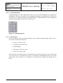
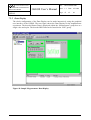
6.4 QLook
The QLook module realizes the easy to use graphical interface between user and experiment.
It benefits the experimenting user while the whole live cycle of the instrument H/W: from the
bench test on a S/C simulator prior the launch to operating the instrument on the flight after
launch.
To facilitate the use of the GSEOS S/W the user interface is conform to common Windows
applications. Nearly the whole configuration can be made interactively on the graphical user
interface. The built in editor allows the user to configure the Data Display easily “on the fly”
while running the experiment. The user interface is divided into three parts:
•
Navigation Tree on the left side: •
•
Data Display on the upper right side: ‚
•
Logging Display on the lower right side: ƒ
Furthermore there are a main menu and a tool bar on the top and a status bar on the bottom
like common Windows applications (see Figure 11).
•
‚
ƒ
Figure 11 Typical GSEOS Display
Institut für Datentechnik
und Kommunikationsnetze
TECHNISCHE UNIVERSITÄT
BRAUNSCHWEIG
Project:
GSEOS
Ref.:
GSEOS User’s Manual
IDA-GSEOS-0001
Issue: 1.2
Date: 6/5/2000
Page: 33
of:
48
6.4.1 Navigation Tree
Within the Navigation Tree various Data Displays are hierarchical collocated. The user can
switch between the Data Displays quickly.
Furthermore all user defined command batch files are listed in the Navigation Tree. They can
be started with a double mouse click on the appropriate batch in the tree.
Beneath the Data Display and the batches the user finds the Control Panel in the Navigation
Tree. With this tool the main settings of all GSEOS modules may be made like the common
Windows Control Panel.
6.4.2 Data Display
One of the most important features of the QLook is its ability to display the instrument data in
various formats in real time. The data blocks from the instrument H/W can be displayed as
numeric scalars or fields, as graphical plots or bar graphs or as an image in any free
configurable format. The representation of the data is made by several QLook Items. There are
Active and Passive QLook Items as well as command buttons.
Because of various requirements in various experiments the QLook Items can be collocated in
various different Data Displays. There are almost no limitations in the number of QLook
Items or in the number of used Data Displays. The user can switch between the Data Displays
easy and quickly using the Navigation Tree.
To document experiment the Data Displays can be printed as hardcopy. The user may define
the format of the print as well as header and footer lines including a caption and the date or
other specific information. Furthermore any single QLook Item can be logged on printer.
Because of the real time character of a test system, QLook does not affect the reaction time of
the GSEOS. So GSEOS modules run in various asynchronous threads on different priority
levels. The paint thread of QLook possesses the least priority level - in time critical situations
the refreshing rate of the Data Display will be reduced.
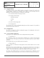
6.4.2.1 Active QLook Items
Active QLook Items and Passive QLook Items realize the Data Display. Active QLook Items
correspond to Block Elements used in any G-Language expression. If the used Block Element
appears at the Decoder module output (see Figure 5), the respective QLook Item is refreshed
(see section 6.3.3.3). Following Active Items are supported:
•
Numeric Display of Scalar Values: •
Native representation of numeric values as single number in multiple formats
(decimal, hexadecimal, octal, binary, floating point, character).
•
Numeric Display of Fields: ‚
Native representation of numeric fields as dump in any arrangement and multiple
formats (decimal, hexadecimal, octal, binary, floating point, character).
Institut für Datentechnik
und Kommunikationsnetze
TECHNISCHE UNIVERSITÄT
BRAUNSCHWEIG
Ref.:
GSEOS User’s Manual
Project:
GSEOS
IDA-GSEOS-0001
Issue: 1.2
Date: 6/5/2000
Page: 34
of:
48
•
Text References: ƒ
Representation of numeric values as predefined text in colors depending on the
value. (The definition of the text references is made in the G-Language project files.)
•
Strings: „
Representation of zero terminated character fields.
•
Graphical Plot: …
Representation of numeric value pairs as graphical plots in multiple formats
(y(t), y(x), etc.).
•
Histogram Chart:
Statistic representation of numeric fields in histogram charts.
•
Image Display: †
Representation of numeric fields as bitmap.
…
†
‚
ƒ
•
„
Figure 12 Active QLook Items
The representation of numeric values offers a high flexibility using a format string known by
the C-language printf function. All values can be displayed in various formats in many
numeric representations like decimal, hexadecimal, octal or binary integer or as floating point
number or as character. It’s possible to combine multiple numeric representations of one
single value.
Institut für Datentechnik
und Kommunikationsnetze
TECHNISCHE UNIVERSITÄT
BRAUNSCHWEIG
Ref.:
GSEOS User’s Manual
Project:
GSEOS
IDA-GSEOS-0001
Issue: 1.2
Date: 6/5/2000
Page: 35
of:
48
Table 4 Format String Conversion Characters
Type Char
Expected Input
Format of Output
%d, %l, %i
Integer
signed decimal integer
%u, %lu
Integer
unsigned decimal integer
%x, %X
Integer
unsigned hexadecimal integer
%o
Integer
unsigned octal integer
%b
Integer
unsigned binary integer
%c
Character
single character
%f, %e, %g,
Floating Point (double)
%E, %G
signed floating point number
6.4.2.2 Passive QLook Items
The Passive Items facilitate the experiment representation on Data Displays. There are
following Passive Items:
•
Static Group Boxes: •
Grouping area like the group boxes of dialog windows.
•
Static Text: ‚
Non-alterable text as caption or comment.
•
Static Pictures: ƒ
Any Windows bitmap file as logo etc.
ƒ
•
‚
Figure 13 Passive QLook Items
Institut für Datentechnik
und Kommunikationsnetze
TECHNISCHE UNIVERSITÄT
BRAUNSCHWEIG
Ref.:
GSEOS User’s Manual
Project:
GSEOS
IDA-GSEOS-0001
Issue: 1.2
Date: 6/5/2000
Page: 36
of:
48
6.4.2.3 Command Buttons
Command buttons are static input Items. They are used to send commands to the instruments
immediately. The user can define any G-Language command or application on a button (see
section 6.3.3.4). Unlike the batches commands send by command buttons will be transmitted
to the H/W immediately in the order of their arrival.
Figure 14 Command Buttons
6.4.2.4 Data Monitor
All Active QLook Items on the Data Display can be monitored automatically. There are five
levels to the monitor classification:
•
Error Level above value
•
Warning Level above value
•
Default Range
•
Warning Level below value
•
Error Level below value
If the data leave the default range user defined actions will be performed. To any warning and
error level the user can define any action in G-Language and additionally the color of the
QLook Item. The occurrence of a warning or error level can be logged on message file or
printer.
Institut für Datentechnik
und Kommunikationsnetze
TECHNISCHE UNIVERSITÄT
BRAUNSCHWEIG
Ref.:
GSEOS User’s Manual
Project:
GSEOS
IDA-GSEOS-0001
Issue: 1.2
Date: 6/5/2000
Page: 37
of:
48
6.4.3 Logging Display
All messages from the various GSEOS modules are logged in a message file viewed by the
Logging Display. Furthermore all commands can be logged as well as messages from user
applications. Following information are displayed to any message:
•
the exact date and time the message occurred
•
the category of the message:
− information message
− warning
− error
•
the source of the messages and
•
the message itself
The messages can be sorted ascending/descending by any of these categories. It is possible to
document the messages as print out.
6.4.4 Configuration
The QLook is designed for efficient configuration support. All configuration work can be
done interactively with the mouse.
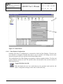
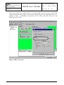
6.4.4.1 General GSEOS Configuration
All properties of the GSEOS modules can be configured interactively with the
•
Control Panel: •
like the Windows settings. The Control Panel of GSEOS can be reached at the Navigation
Tree on the left side. Any single icon listed in the Control Panel represents a specific module
of GSEOS.
After a double click on an icon with the mouse the respective
•
Property Sheet: ‚
opens (see Figure 15). With this tool all properties of the selected module can be set easily
and quickly.
Any Property Sheet contains multiple pages - each page has a tab that the user can select to
bring the page to the foreground. To confirm the changed settings the user may press “OK” or
“Apply”; to close the Property Sheet without any changes the use may press “Cancel”.
All settings of the GSEOS modules are stored in one configuration file: “GSEOS.ini”. So all
settings can be easily backed up and recovered. There is no need to edit this text file directly.
Institut für Datentechnik
und Kommunikationsnetze
TECHNISCHE UNIVERSITÄT
BRAUNSCHWEIG
Ref.:
GSEOS User’s Manual
Project:
GSEOS
IDA-GSEOS-0001
Issue: 1.2
Date: 6/5/2000
Page: 38
of:
48
•
‚
Figure 15 Control Panel
6.4.4.2 Data Display Configuration
Probably most time in configuration is consumed to build the Data Displays. Therefore the
user interface is designed to handle this task as easy as possible. All settings can be done
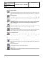
interactively quick and easy with the built-in Data Display editor.
The configuration of the Data Display corresponds to common graphical editors. Tool bar and
context sensitive menus are used. The QLook editor relevant part of the tool bar consist of
following functions:
Toggle Edit Mode On/Off:
With this button the user can switch between the operation mode and the edit
mode. Configuration changes can be done in edit mode only.
Institut für Datentechnik
und Kommunikationsnetze
TECHNISCHE UNIVERSITÄT
BRAUNSCHWEIG
Ref.:
GSEOS User’s Manual
Project:
GSEOS
IDA-GSEOS-0001
Issue: 1.2
Date: 6/5/2000
Page: 39
of:
48
If the edit mode is enabled one of the following tools can be chosen:
Selection Mode:
In the selection mode Items can be selected, moved or resized. With a click of the
right mouse button within an Item area the context menu appears to configure the
Item.
Insert Data Item:
Any number of Active QLook Items can be placed. With a click of the right
mouse button within the Item area the context menu appears to configure the Item.
Insert Static Text:
Any number of static text Items can be placed. With a click of the right mouse
button within the Item area the context menu appears to configure the Item.
Insert Group Box:
Any number of group boxes can be placed. With a click of the right mouse button
within the Item area the context menu appears to configure the Item.
Insert Command Button:
Any number of command buttons can be placed. With a click of the right mouse
button within the Item area the context menu appears to configure the Item.
Insert Static Picture:
Any number of static pictures can be placed. With a click of the right mouse
button within the Item area the context menu appears to configure the Item.
Following edit tools can be also used:
Cut out selected Items:
All selected Items will be cut out from the Data Display and copied to the
clipboard.
Copy selected Items:
All selected Items will be copied to the clipboard.
Paste Items:
All Items stored in the clipboard will be inserted in the Data Display on the same
position as the stored Items.
Institut für Datentechnik
und Kommunikationsnetze
TECHNISCHE UNIVERSITÄT
BRAUNSCHWEIG
Ref.:
GSEOS User’s Manual
Project:
GSEOS
IDA-GSEOS-0001
Issue: 1.2
Date: 6/5/2000
Page: 40
of:
48
To change any QLook Item the user has to switch from Operational Mode to the Edit Mode at
first. This mode does not affect the system - all settings can be done while the system is
running.
In the selection mode any number of QLook Items can be selected. If the Item is sizeable
small carets called “chooser” appears around the corners of the selected Item. Using this
choosers the height or the width of the Item can be changed several or at once (see Figure 16):
Figure 16 Sizing of QLook Items
All QLook Items will be placed and fit to an internal logical grid. So the Data Displays have
the same appearance on different display resolutions.
To change the properties of the selected Items the user has to click within the selected area
with the right mouse button. If the user choose the Item “Properties” in the context menu a
single Property Sheet will appear (see Figure 17). The style of this tool is common to the
Control Panel. Following Item attributes can be set:
•
Data Settings (if there are Active Items or command buttons selected):
− G-Language expression to define the QLook Item
− kind of view of the data
− format string
− separator string (space, colon, etc. to separate columns in arrays)
− arrangement of arrays
− zoom factors of images
•
Text Settings:
− caption (command buttons, group boxes and static text)
− kind of font, size and style,
− text alignment
•
Color Settings:
− default fore- and background color
− fore- and background colors of the different monitor levels or the text references
− use of default or user defined colors
Institut für Datentechnik
und Kommunikationsnetze
TECHNISCHE UNIVERSITÄT
BRAUNSCHWEIG
Ref.:
GSEOS User’s Manual
Project:
GSEOS
•
IDA-GSEOS-0001
Issue: 1.2
Date: 6/5/2000
Page: 41
of:
48
Item Style:
− position and size (useful in multi-selections)
− frame style of group boxes
− picture file of static pictures
Figure 17 QLook Item Attributes
Same as QLook Items the Data Display background can be customized. If the user click with
the right mouse button in the Data Display background out of any Item, the related context
menu will appear. In the Property Sheet that opens, after the user choose “Properties”, a
background color or a background picture can be set. If the picture does not fill the Data
Display area the Data Display area will be tiled.
All settings of a single Data Display are stored in single file with the extension “.scn” as
simple text. It’s possible to edit this files directly in any text editor (the file syntax is described
in the document IDA-GSEOS-0005: GSEOS Data Display Language Description).
Institut für Datentechnik
und Kommunikationsnetze
Ref.:
TECHNISCHE UNIVERSITÄT
BRAUNSCHWEIG
GSEOS User’s Manual
Project:
GSEOS
IDA-GSEOS-0001
Issue: 1.2
Date: 6/5/2000
Page: 42
of:
48
7 Configuration Example
This chapter describes a possible configuration of the GSEOS for a small magnetometer
experiment.
7.1 Experiment Description
7.1.1 Telemetry Format
The magnetometer sends two types of telemetry packets. Their format is shown in the next
table.
•
Sensor Data is sent every second if the sensor is active.
•
H/K Data is sent after a “Send H/K” command.
The telemetry transmits data in separate blocks of 16 bytes each, in motorola format.
Table 5 Telemetry Definition
Type
Byte
Sensor Data
0
0xEB – Sync. byte
1
0x90 – Sensor data
2-5
H/K Data
Description
Magnetometer readout
Range
0 ... 42949672.96 nT
Resolution
0.01 nT
0
0xEB – Sync. byte
1
0x91 – H/K data
2
Sensor Status
0-inactive
1-active
3-4
Temperature
-130 °C ... +130 °C
0.016 K
5-6
+5V voltage
0 ... 7.65 V
30 mV
7-8
+5V current
0 ... 306.00 mA
1.20 mA
Institut für Datentechnik
und Kommunikationsnetze
Ref.:
TECHNISCHE UNIVERSITÄT
BRAUNSCHWEIG
GSEOS User’s Manual
Project:
GSEOS
IDA-GSEOS-0001
Issue: 1.2
Date: 6/5/2000
Page: 43
of:
48
7.1.2 Command Format
Two commands can be sent to the magnetometer. The first command activates the sensor
measurement; the second command requests sensor H/K data.
Table 6 Command Definition
Command
Activate Sensor
Measurement
H/K Packet Request
Byte
Description
0
0x01 – Command identifier
1
0x00 – Set sensor inactive
0x01 – Set sensor active
0
0x02 – Command identifier
7.2 GSEOS Configuration
Two main configuration parts of the GSEOS are needed:
•
Configuration File. The configuration file is written in the GSEOS configuration
language. It contains:
− Block Definitions. The block definition describes all elements within the
telemetry data by type, offset, length and name. All elements are accessible by
their names.
− Decoder. The decoder functions are executed automatically each time when a
specific data block arrives. In this example the decoder is used to separate
science data and H/K data from the telemetry data stream.
− Functions. Functions are used to command the magnetometer.
•
Data Display. The Data Display is the visual interface between the magnetometer
experiment and the operator. It contains of command buttons and Items to visualize
the experiment data.
Institut für Datentechnik
und Kommunikationsnetze
TECHNISCHE UNIVERSITÄT
BRAUNSCHWEIG
Project:
GSEOS
Ref.:
GSEOS User’s Manual
IDA-GSEOS-0001
Issue: 1.2
Date: 6/5/2000
Page: 44
of:
48
7.2.1 Configuration File
The listing below shows the complete configuration file for this magnetometer experiment,
where the previously defined configuration part can easily be identified.
//-----------------------------------------------------------------------------//
// Project: Sample Project
// File:
main.g
//
// Copyright (C) 1999, IDA
// Author: Kai Stoeckner
//
//-----------------------------------------------------------------------------//-----------------------------------------------------------------------------// includes
//-----------------------------------------------------------------------------#include "gseos.g"
// common defines, Runtime Library prototypes, etc.
//******************************************************************************
// block definitions
//******************************************************************************
// raw telemetry data
typedef union
{
struct
{
UCHAR ucSync;
UCHAR ucType;
UCHAR uc[14];
};
UCHAR ucRaw[];
} tsRawTelemetry;
// Sensor Data packet
typedef motorola union
{
struct
{
UCHAR ucSync;
UCHAR ucType;
ULONG ulData;
};
UCHAR ucRaw[];
} tsSensorData;
// H/K Data packet
typedef motorola union
{
struct
{
UCHAR ucSync;
UCHAR ucType;
UCHAR ucStatus;
USHORT usTemp;
USHORT usVoltage5V;
USHORT usCurrent5V;
};
UCHAR ucRaw[];
} tsHkData;
Institut für Datentechnik
und Kommunikationsnetze
TECHNISCHE UNIVERSITÄT
BRAUNSCHWEIG
Project:
GSEOS
Ref.:
GSEOS User’s Manual
IDA-GSEOS-0001
Issue: 1.2
Date: 6/5/2000
Page: 45
of:
48
//-----------------------------------------------------------------------------// block declarations
//-----------------------------------------------------------------------------blockdef tsRawTelemetry tblkRawTelemetry RawTelemetry;
// Raw telemetry
blockdef tsSensorData
tblkSensorData
SensorData;
// Sensor data
blockdef tsHkData
tblkHkData
HkData;
// H/K data
// Is this simple project lets assume that commands to the magnetometer are
// routed through a H/W driver. There are different channels for network, serial,
// parallel, etc. So we can easily switch to an other destination.
#define CMDCHANNEL_MAGNETOMETER 0x01000042
//******************************************************************************
// decoder
//******************************************************************************
//-----------------------------------------------------------------------------//
// decode on (RawTelemetry)
//
// The decoder in allotted to the raw telemetry data block transmitted from the
// magnetometer. Depend on sync and type a new data or H/K block is generated.
//
//-----------------------------------------------------------------------------decode on (RawTelemetry)
{
tblkSensorData Data;
tblkHkData
Hk;
if (RawTelemetry.ucSync == 0xEB)
{
switch (RawTelemetry.ucType)
{
case 0x90:
Data.ucRaw = RawTelemetry.ucRaw[0, sizeof (Data.ucRaw)];
send (Data);
break;
case 0x91:
Hk.ucRaw = RawTelemetry.ucRaw[0, sizeof (Hk.ucRaw)];
send (Hk);
break;
}
}
}
//-----------------------------------------------------------------------------//
// decode on (_Timer1Sec)
//
// A global system generated 1 sec. Timer. The ticker requests H/K packets
// from magnetometer.
//
//-----------------------------------------------------------------------------decode on (_Timer1Sec)
{
RequestHk ();
}
Institut für Datentechnik
und Kommunikationsnetze
TECHNISCHE UNIVERSITÄT
BRAUNSCHWEIG
Ref.:
GSEOS User’s Manual
Project:
GSEOS
IDA-GSEOS-0001
Issue: 1.2
Date: 6/5/2000
Page: 46
of:
48
//******************************************************************************
// functions
//******************************************************************************
//-----------------------------------------------------------------------------//
// VOID ActivateSensor (UCHAR ucActive)
//
// The function activates/disactivates the Sensor. The sensor sends status packes
// every one second on active state.
//
// Parameters: ucActive - 0: set sensor inactive
//
1: set sensor active
//
//-----------------------------------------------------------------------------VOID ActivateSensor (UCHAR ucActive)
{
UCHAR ucParameter[2];
ucParameter[0] = 0x01;
ucParameter[1] = ucActive;
_SendCommandUByte (CMDCHANNEL_MAGNETOMETER, ucParameter, sizeof (ucParameter), 1);
} // ActivateSensor
//-----------------------------------------------------------------------------//
// VOID RequestHk ()
//
// The function requests a H/K packet from sensor.
//
//-----------------------------------------------------------------------------VOID RequestHk ()
{
UCHAR ucParameter[1] = 0x02;
_SendCommandUByte (CMDCHANNEL_MAGNETOMETER, ucParameter, sizeof (ucParameter), 0);
}
//-----------------------------------------------------------------------------// text references
//-----------------------------------------------------------------------------text OffOn
{
0:
"Off", 0;
1:
"On", 1;
default: "?",
2;
}
Institut für Datentechnik
und Kommunikationsnetze
TECHNISCHE UNIVERSITÄT
BRAUNSCHWEIG
Ref.:
GSEOS User’s Manual
Project:
GSEOS
IDA-GSEOS-0001
Issue: 1.2
Date: 6/5/2000
Page: 47
of:
48
7.2.2 Data Display
The whole configuration of the Data Display can be made interactively using the graphical
user interface of the GSEOS. The next figure shows the Data Display for the magnetometer
experiment. The decoded Sensor Data is displayed within the “Measurement” group box as a
single value and a plot. The decoded H/K Data can be found in the “H/K” group.
Figure 18 Sample Magnetometer Data Display
Institut für Datentechnik
und Kommunikationsnetze
TECHNISCHE UNIVERSITÄT
BRAUNSCHWEIG
Ref.:
GSEOS User’s Manual
Project:
GSEOS
IDA-GSEOS-0001
Issue: 1.2
Date: 6/5/2000
Page: 48
of:
48
The decoder within the configuration file is not responsible for the conversion of the H/K
values into physical units. Figure 19 shows the Property Sheet for the temperature Item. It is
possible to enter a mathematical expression for the H/K conversion directly in the
“Data/Expression” field.
Figure 19 H/K Conversion