1
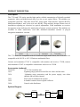
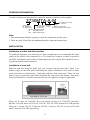
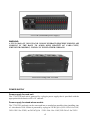
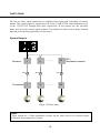
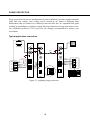
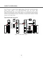
FIBER OPTIC TRANSMISSION SYSTEM
3730 & 3530 SERIES
Digital Video with Bi-directional/Return Data
User Manual
Infinova
Contents
SERVICE NOTICE..................................................................................................... 1
PRODUCT DESCRIPTION ........................................................................................ 2
ORDERING INFORMATION ...................................................................................... 3
INSTALLATION .......................................................................................................... 3
POWER SUPPLY ...................................................................................................... 4
TRANSMITTER PANEL ............................................................................................. 6
MINIATURE TRANSMITTER PANEL ........................................................................ 7
2F MINIATURE TRANSMITTER PANEL ................................................................... 8
RECEIVER PANEL .................................................................................................... 9
DIP SWITCH SETTINGS ......................................................................................... 10
TYPICAL SYSTEM CONNECTION ......................................................................... 11
One video with one return RS422 data ............................................................. 11
One video with return Manchester/Biphase Data ............................................. 12
One video with duplex RS422 data................................................................... 13
One video with duplex Manchester/Biphase data ............................................. 14
One video with full duplex RS485 data ............................................................. 15
One video with half duplex RS485 data ............................................................ 16
NETWORK MANAGEMENT .................................................................................... 17
DAISY CHAIN .......................................................................................................... 18
SURGE PROTECTION............................................................................................ 19
TRANSMISSION REPEATER ................................................................................. 20
CONTACT CLOSURE SIGNAL ............................................................................... 21
CODE DISTRIBUTOR ............................................................................................. 22
SERVICE NOTICE
The installation of this product should be made by qualified personnel. Do not attempt to
service this product yourself. Refer all servicing to qualified personnel.
If you require information during installation of this product or if service seems necessary,
contact the local suppliers or Infinova at 1-732-355-9100 in 51 Stouts Lane, Monmouth
Junction, NJ 08852 U.S.A. You must obtain a Return Authorization Number and shipping
instructions before returning any product for service.
Our obligation under this warranty is limited only to the repair or replacement of any of
our products, provided that products are used within the specified ratings and applications,
and that products are applied in accordance with good engineering practices, and that
products are proved by our examination to be defective.
This warranty does not extend to any Infinova products which have been subject to acts of
accident, misuse, abuse, neglect, improper application or installation, improper operation
or maintenance, connection to an improper voltage supply or to materials which have
been altered or repaired outside an authorized Infinova factory repair center.
Information provided by Infinova is accurate and reliable. However, no responsibility is
assumed by Infinova for its use; nor for any infringements of other rights of third parties
which may result from its use. No license is granted by implications or otherwise under
any patent or patent rights of Infinova.
WARNING
TO REDUCE THE RISK OF FIRE OR SHOCK HAZARD, DO NOT EXPOSE THIS PRODUCT TO
RAIN OR MOISTURE.
DO NOT LOOK INTO OPTICAL PORTS WITH POWER ON.
1
PRODUCT DESCRIPTION
Description
The 3730 and 3530 series provide high quality reliable transmission of digitally encoded
composite video and bidirectional data over one or two optical fibers. The modules are
compatible with PAL, SECAM, and NTSC video signal. Data interface supports RS422,
Manchester/Biphase, and 2-wire-or-4-wire RS485. Plug-and-play design ensures ease of
installation requiring no electrical or optical adjustments. Each transmitter or receiver
incorporates status indicators for monitoring of proper system operation. The modules are
available in either stand-alone, card unit, miniature-transmitter module or plug-in
integration transmitter versions.
Stand-alone
module
Card unit
Miniature
transmitter
Plug-in integration
transmitter
The 3730 series are compatible with 9/125micron single-mode fibers; the 3530 series are
compatible with 50/125 or 62.5/125micron multimode fibers.
Camera end transmitter 3730T is compatible with monitor end receiver 3730R; camera
end transmitter 3530T is compatible with monitor end receiver 3530R.
Accessories (optional)
3910-000
19" 1U fan assembly unit
3932
Lightning surge protection card for one video and one data
3934
Lightning surge protection card for power supply, one video
channel and one data channel
3951
Fiber optical transmission repeater
3952
8-channel contact closure signals collector
3954
Control code distributor
System Diagram
Transmitter
Receiver
V
V
D
3730TA
3730RA
fiber
2
Monitor
D
ORDERING INFORMATION
Use the Configuration chart below to select the options available for this product.
3730MTA-A-M
Fiber Type
Product Type Distance
35 Multimode
T Transmitter A 25km
37 Singlemode
R Receiver
Network management (NM)
M
With NM function
Omit Without NM function
M stand-alone module
R card unit
Enclosur
e
A Miniature
transmitter
B Plug-in integration transmitter
Note:
1. The transmission distance category is valid for singlemode product only.
2. There are only TA and RA for multimode product, and can transmit 2km.
INSTALLATION
Installation of video and data interface
To install the apparatus, it is necessary to allow enough space to accommodate the bend
radius of the optical cable connected to it. The transceiver requires as short as practical
one BNC terminated coaxial cable to input/output the video signal. Data interfaces uses a
4-position terminal block connector.
Installation of card unit
Push the card unit along the guide rails (not in spaces between the rails). There is an
Infinova logo on the front panel indicating the proper orientation. Press hard to make
good connection to motherboard - loud snap indicates firm connection. There are two
captive screws on the front panel that can fasten the card unit to the subrack. They must
be locked by hand in a clockwise manner (do not over tighten), see figure right below.
Full load of 3910-18S
There are 18 slots on 3910-18S. So it can mount 18 pieces of 3730/3530 card unit.
Besides 3910-18S, there are 3910-1S, 3910-2S, 3910-3S, 3910-4S and 3910-15R optional.
There are 1 slot on 3910-1S, 2 slots on 3910-2S, 3 slots on 3910-3S, 4 slots on 3910-4S
and 15 slots on 3910-15R respectively.
3
3910-15R (Redundant power supply)
WARNING:
A FULL LOAD OF 3910-15R AND 3910-18S SUBRACK REQUIRES FORCED AIR
COOLING IN THE RACK. TO AVOID OVER HEATING OF CARD UNITS,
WHENEVER POSSIBLE, INSTALL IN EVERY OTHER SUBRACK.
Forced air cooling with 3910-000
POWER SUPPLY
Power supply for card unit
The 3730/3530 card unit is powered by a plug-in power supply that is provided with the
appropriate desk chassis or EIA 19" subrack.
Power supply for stand-alone module
The 3730/3530 card unit can be converted into a stand-alone module when installing into
a 1-slot chassis 3910-1S that is powered by a plug-in 12VDC@1A (3921-12D-1 for 110V;
3921-12D-2 for 230V) or 24VAC@1A(3921-24A-1 for 110V;3921-24A-2 for 230V)
4
power supply. Plug the wires into the connectors, fasten the screws to make a firm
connection, see figure below.
3921 power supply
Connection Diagram
Power supply for miniature transmitter module
The miniature transmitter module is
powered by a plug in
12VDC/24VAC@1A power supply
3921. Join the female connector to
the module to power-on the module.
Power supply for plug-in
integration transmitter
There is no additional power supply
Power connection of miniature transmitter
needed for plug-in integration
transmitter, once the plug-in
integration transmitter card is integrated into the dome, it’s powered by the dome’s power
supply.
Note:
When the series is powered together with other devices (cameras and etc.) by a single
24VAC power source, please make sure that the related device has a full-wave
(bridge) rectifier circuit.
5
TRANSMITTER PANEL
PWR
Power on indicator(red)
VP
Video input indicator(green)
Video input, 75ohm, 1VP-P
Chassis GND
Earthing for lightning surge protection
Optical port, FC or ST
OP
Optical link loss indicator(red)
Data output indicator(green)
1
2
4-position 3.5mm central spacing
terminal block connector
3
4
Data input indicator(green)
1 2 3 4
ON
4-position DIP switch for setting line termination,
status monitoring and data format
1#: enable/disable line termination
2#: enable/disable remote status monitoring
3#: setting data format
4#: setting data format
Note: see table 1 for details
Figure 1. Transmitter panel
6
MINIATURE TRANSMITTER PANEL
12VDC
24VAC
Power supply interface
Video
I/O
Power on indicator(red)
Video input, 75ohm, 1VP-P
Video input indicator(green)
Data
Out
Data output indicator(green)
In
4-position 3.5mm central spacing
terminal block connector
Data input indicator(green)
Optical
Port
Optical link loss indicator(red)
Optical port, FC or ST
Figure 2. Miniature transmitter panel
7
2F MINIATURE TRANSMITTER PANEL
12VDC
24VAC
Power supply interface
Video
I/O
Power on indicator(red)
Video input, 75ohm, 1VP-P
Video input indicator(green)
Data
Out
Data output indicator(green)
In
4-position 3.5mm central spacing
terminal block connector
in
Optical port, FC or ST
Optical port, FC or ST
Optical
Port
Optical link loss indicator(red)
out
Data input indicator(green)
Figure3. 2F miniature transmitter panel
8
RECEIVER PANEL
PWR
Power on indicator(red)
VP
Video output indicator(green)
Video output, 75ohm, 1Vp-p
Chassis GND
Earthing for lightning surge protection
Optical port, FC or ST
OP
Optical link loss indicator(red)
Data output indicator(green)
1
2
4-position 3.5mm central spacing
terminal block connector
3
4
Data input indicator(green)
1 2 3 4
ON
4-position DIP switch for setting line termination,
status monitoring and data format
1#: enable/disable line termination
2#: enable/disable remote status monitoring
3#: setting data format
4#: setting data format
Note: see table 1 for details
Figure 4. Receiver panel
9
DIP SWITCH SETTINGS
DIP-1 is to set line termination resistor; set it ON/OFF to connect/disconnect 120Ω
termination resistor between Pin 3 and Pin 4. DIP-2 is to set the network management
function, set it ON/OFF to disable/enable the Network Management function. If there is
no NM function, make sure that DIP-2 is set ON. DIP-3 and DIP-4 are to set the data
format. They should be identical on both transmitter and receiver for specified data.
Termination resistor
A multipoint bus architecture requires termination at both ends of the bus line to restrain
signal reflection. The termination resistors must be within 20 percent of the characteristic
impedance of the cable and can vary from 90 Ω to 120 Ω.
Data format
DIP
Transmitter
1
Full duplex 4 - wire RS485
(OFF, OFF)
OFF
OFF
3
4
2
3
4
1
RS422/Manchester/Biphase
(OFF, ON)
OFF
ON
3
4
Receiver
Out +
1
Out -
2
In +
3
In -
4
Out +
1
(ON, OFF)
OFF
3
4
Out -
In +
3
In +
3
In -
4
RS422/Manchester/Biphase
1
ON
(ON, ON)
In -
1
2
D+
3
D+
D-
4
3
4
Out +
3
D-
ON
In -
2
2
Return
In +
Out -
1
ON
Out -
2
4
Half duplex 2 - wire RS485
Out +
4
Out +
2
Out -
3
Out +
4
Out -
}CH1
}CH2
1
2
3
4
In +
In -
Table 1. DIP SWITCH SETTING REFERENCE
Location of DIP switch:
Plug-in integration transmitter
Miniature transmitter mode
For the detailed location of the DIP switch on transmitter and receiver, please refer to
TRANSMITTER PANEL and RECEIVER PANEL
10
TYPICAL SYSTEM CONNECTION
One video with one return RS422 data
PWR
PWR
VP
VP
Monitor
Super Dome
fiber
Earthing
Earthing
OP
OP
R+
R+
Data out +
R-
Data out -
1
2
3
4
T+
T-
R-
1
2
3
4
Gnd
Connector
1234
1 2 3 4
ON
1234
Connector
T-
Data in -
←
Gnd
T+
Data in +
RS422
3730T
Keyboard
3730R
←
1 23 4
ON
1 23 4
ON
←
Line termination
None termination
Figure 5. One video with one return RS422 data
Note:
1. User can get RS422 signal from the transmitter’s Pin 3 and Pin 4 at one time.
2. Set DIP-1 ON to connect a 120Ω termination resistor whenever termination resistor is
required.
11
TYPICAL SYSTEM CONNECTION
One video with return Manchester/Biphase Data
PWR
PWR
VP
VP
Monitor
Super Dome
fiber
Earthing
B
W
Earthing
OP
OP
Data out +
1
2
3
4
1
2
3
4
Data out -
S
W
S
Connector
1234
1234
1 2 3 4
ON
←
Connector
B
Data in +
Data in -
Manchester
Biphase
3730T
Keyboard
3730R
←
1 23 4
ON
1 23 4
ON
←
Line termination
None termination
Figure 6. One video with one return Manchester/Biphase data
Note:
1. User can get Manchester signal from the transmitter’s Pin 3 and Pin 4 at one time.
2. Set DIP-1 ON to connect a 120Ω termination resistor whenever termination resistor is
required.
12
TYPICAL SYSTEM CONNECTION
One video with duplex RS422 data
PWR
PWR
VP
VP
Monitor
Super Dome
fiber
Earthing
Earthing
OP
OP
Data out +
R+
R-
Data out +
Data out -
T+
Data in +
T-
Data in -
Data out -
1
2
3
4
1
2
3
4
Data in +
Data in -
RT+
TGnd
Connector
Gnd
1234
1234
1 2 3 4
ON
←
Connector
R+
RS422
3730T
Keyboard
3730R
←
1 23 4
ON
1 23 4
ON
←
Line termination
None termination
Figure 7. One video with duplex RS422 data
Note:
Set DIP-1 ON to connect a 120Ω termination resistor whenever termination resistor is
required.
13
TYPICAL SYSTEM CONNECTION
One video with duplex Manchester/Biphase data
PWR
PWR
VP
VP
Monitor
Super Dome
fiber
Earthing
Earthing
OP
OP
Data out +
R+
R-
Data out +
Data out -
T+
Data in +
T-
Data in -
Gnd
Data out -
1
2
3
4
1
2
3
4
Data in +
Data in -
T+
T-
1234
1 2 3 4
ON
1234
3730T
R-
Gnd
Connector
←
Connector
R+
Manchester
Biphase
←
1 23 4
ON
1 23 4
ON
←
Keyboard
3730R
Line termination
None termination
Figure 8. One video with duplex Manchester/Biphase data
Note:
Set DIP-1 ON to connect a 120Ω termination resistor whenever termination resistor is
required.
14
TYPICAL SYSTEM CONNECTION
One video with full duplex RS485 data
PWR
PWR
VP
VP
Monitor
Super Dome
fiber
Earthing
Earthing
OP
OP
Data out +
R+
R-
Data out +
1
2
3
4
Data out -
T+
Data in +
T-
Data in -
1
2
3
4
Data out Data in +
Data in -
RT+
TGnd
Connector
Gnd
1234
1234
1 2 3 4
ON
←
Connector
R+
RS485
3730T
3730R
←
1 23 4
ON
1 23 4
ON
←
Keyboard
Line termination
None termination
Figure 9. One video with full duplex RS485 data
Note:
Set DIP-1 ON to connect a 120Ω termination resistor whenever termination resistor is
required.
15
TYPICAL SYSTEM CONNECTION
One video with half duplex RS485 data
PWR
PWR
VP
VP
Super Dome
fiber
Earthing
D-
Earthing
OP
OP
D+
Monitor
1
2
3
4
1
2
3
4
Data +
Data -
Gnd
Data +
Data -
Gnd
Connector
1234
1234
1 2 3 4
ON
←
Connector
D+
D-
2-wire RS485
3730T
3730R
←
1 23 4
ON
1 23 4
ON
←
Keyboard
Line termination
None termination
Figure 10. One video with half duplex RS485 data
Note:
Set DIP-1 ON to connect a 120Ω termination resistor whenever termination resistor is
required.
16
NETWORK MANAGEMENT
The 3730 and 3530 series can add a network management system. After installing the NM
system N3981, the remote transmitters send their running status to their respective
receivers. The network management board collects and sends all the status information of
the transmitters and the receivers to a host PC. With the network management software,
users can survey the status of the remote transmitters and central receivers on the host PC
conveniently, and can check all of the historical running status from the alarm log.
The list below shows all of the status which the Network Management system can
monitor:
1. the power supply status of transmitter and receiver
2. the optical link status of transmitter and receiver
3. the video signal status of transmitter and receiver
4. the data status of transmitter and receiver
Figure 11. Network management software
WHEN NETWORK MANAGEMENT FUNCTION IS ENABLE, THE
TRANSMISSION SYSTEM CAN ONLY TRANSMIT RETURN DATA!
DIP-2 is to enable/disable remote status monitoring, set it OFF to ENBALE the network
management function.
←
1 2 3 4
ON
Note:
If customer needs the network
management function, please
order a network management card
N3946 in addition.
1 2 3 4
ON
←
SNM Enabled, DIP-2 off
SNM Disabled, DIP-2 on
17
DAISY CHAIN
We can use daisy chain connection to simplified the wiring and controlling of remote
domes. The control signal is connected to all of the 3730R/3530R, and transmitted to all
of the 3730T/3530T through fiber optic respectively. In the remote site, the specified
dome will act as the control signal instructs. The number of video receiver daisy-chained
depends on the driving capability of code source.
System Diagram
Receiver
1
fiber
Transmitter
2
...
120Ω
Termination resistor
fiber
fiber
1
32
2
...
32
Figure 12. Daisy chain
Note:
There should be a 120Ω termination resistor on the final receiver for restrain signal
reflection. Pay attention to it, please.
18
SURGE PROTECTION
Surge protection circuits are implemented to protect Infinova’s products against transient
surge and over voltage. Over voltage can be caused by AC power or lightning flash
disturbances that are induced or conducted onto the data line. It’s important that good
earthing or grounding be applied to ensure the proper function of surge protection circuit.
For reinforced protection, 3932 and 3934 are strongly recommended to protect your
investment.
Typical application connection
PWR
PWR
OUT
Super Dome
VP
VP
fiber
IN
Earthing
Monitor
Earthing
OP
OP
Earthing
Data out +
R+
R-
Data out +
1
2
3
4
Data out -
Data out -
T+
Data in +
T-
Data in -
1
2
3
4
Data in +
Data in -
R+
RT+
TGnd
Connector
←
1234
1234
Connector
1 2 3 4
ON
Gnd
1
2
3
4
1
2
3
4
RS422
3932
3730T
3730R
Figure 13. Lightning surge protection
19
Keyboard
TRANSMISSION REPEATER
The 3951 series is used between transmitter and receiver to extend the transmission
distance of fiber optical system. It magnifies the optical signal received from transmitter,
and sends it to receiver. By using a 3951, the transmission distance of the system is
doubled.
Typical application connection
PWR
PWR
VP
VP
Monitor
Super Dome
O
U
T
Fiber
Earthing
Earthing
OP
OP
R+
R+
R-
Data out+
1
2
3
4
Data out-
T+
1
2
3
4
Fiber
Data in -
T+
TGnd
Connector
TGnd
3730T
I
N
1234
1234
Connector
RData in +
3951
Figure 14. Transmission repeater
20
3730R
Keyboard
CONTACT CLOSURE SIGNAL
The 3952 series is a contact closure signals collector. This series can convert the input
contact closure signals to one RS232/RS422/RS485 data, and convert input
RS232/RS422/RS485 data to 8-ch unidirectional or 4-ch bidirectional contact closure
signals. It can transmit the contact closure signals over a long distance when connecting
with fiber optical transmission system. The number of contact closure channels is default
setting, so are the data format.
Typical application connection
PWR
PWR
Monitor
Fiber
Earthing
R+
GND
Alarm in3
GND
Alarm in4
GND
Remote
Sensor
Alarm in5
GND
Alarm in6
GND
OP
OP
3952T
Earthing
T+
T-
R+
Gnd
R-
1
2
3
4
1
2
3
4
Connector
Data -
T+
TGnd
Connector
1234
1
2
3
4
5
6
7
8
9
10
11
12
13
14
15
16
1234
Alarm in7
GND
Alarm in8
GND
1
2
3
4
Data +
Earthing
R-
Earthing
Alarm in2
GND
PWR
Super Dome
1
2
3
4
Alarm in1
VP
VP
PWR
3730T
3730R
Figure 15. Contact closure signal
21
Keyboard
1
2
3
4
5
6
7
8
9
10
11
12
13
14
15
16
3952R
COM1
N.O.1
COM2
N.O.2
COM3
N.O.3
COM4
N.O.4
COM5
N.O.5
COM6
N.O.6
COM7
N.O.7
COM8
N.O.8
Alarm
Panel
CODE DISTRIBUTOR
The 3954 is a code distributor designed for star connection where the code source is too
far away from the video receiver and overload or reflection occurs.
3954
120Ω
termination
1
120Ω
termination
2
Fiber
Fiber
1
120Ω
termination
3
4
Receiver
4
Transmitter
Fiber
Fiber
2
120Ω
termination
3
Figure 16. Code distributor diagram
22
51 Stouts Lane, Monmouth Junction, NJ 08852, U.S.A.
Tel: 1-888-685-2002(toll-free, USA)
1-732-355-9100
Fax:1-732-355-9101
E-mail: [email protected]
V2.4 0807