1
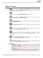
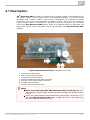
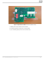
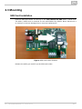
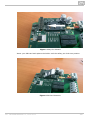
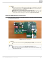
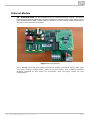
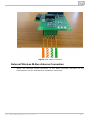
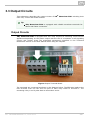
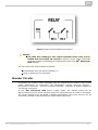
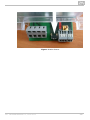
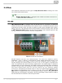
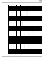
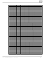
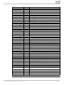
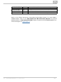
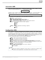
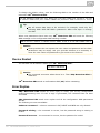
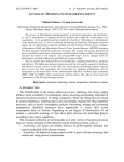
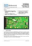
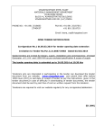
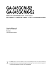
2N® MeterCom PRO
Communication Module for Electricity Meters
User Manual
Firmware
Version
1.0.x
1.0.1
www.2n.cz
The 2N TELEKOMUNIKACE a.s. is a Czech manufacturer and supplier of telecommunications
equipment.
The product family developed by 2N TELEKOMUNIKACE a.s. includes GSM gateways, private
branch exchanges (PBX), and door and lift communicators. 2N TELEKOMUNIKACE a.s. has
been ranked among the Czech top companies for years and represented a symbol of
stability and prosperity on the telecommunications market for almost two decades. At
present, we export our products into over 120 countries worldwide and have exclusive
distributors on all continents.
2N® is a registered trademark of 2N TELEKOMUNIKACE a.s. Any product and/or other
names mentioned herein are registered trademarks and/or trademarks or brands protected
by law.
2N TELEKOMUNIKACE a.s. administers the FAQ database to help you quickly find
information and to answer your questions about 2N products and services. On
www.faq.2n.cz you can find information regarding products adjustment and instructions for
optimum use and procedures „What to do if...“.
2N TELEKOMUNIKACE a.s. hereby declares that the 2N® MeterCom PRO product complies
with all basic requirements and other relevant provisions of the 1999/5/EC directive. For
the full wording of the Declaration of Conformity see the CD-ROM (if enclosed) or our
website at www.2n.cz.
The 2N TELEKOMUNIKACE a.s. is the holder of the ISO 9001:2009 certificate. All
development, production and distribution processes of the company are managed by this
standard and guarantee a high quality, technical level and professional aspect of all our
products.
Content
Content
1. Product Overview . . . . . . . . . . . . . . . . . . . . . . . . . . . . . . . . . . 4
1.1 Product Description . . . . . . . . . . . . . . . . . . . . . . . . . . . . . . . . . . . . . . . . . . . . . . 5
1.2 Upgrade . . . . . . . . . . . . . . . . . . . . . . . . . . . . . . . . . . . . . . . . . . . . . . . . . . . . . . . 7
1.3 Terms and Symbols Used . . . . . . . . . . . . . . . . . . . . . . . . . . . . . . . . . . . . . . . . . 8
2. Description and Installation . . . . . . . . . . . . . . . . . . . . . . . . . . 9
2.1 Description . . . . . . . . . . . . . . . . . . . . . . . . . . . . . . . . . . . . . . . . . . . . . . . . . . . . . 10
2.2 Before You Start . . . . . . . . . . . . . . . . . . . . . . . . . . . . . . . . . . . . . . . . . . . . . . . . . 12
2.3 Mounting . . . . . . . . . . . . . . . . . . . . . . . . . . . . . . . . . . . . . . . . . . . . . . . . . . . . . . . 13
3. Function and Use . . . . . . . . . . . . . . . . . . . . . . . . . . . . . . . . . . 22
3.1 Putting in Operation . . . . . . . . . . . . . . . . . . . . . . . . . . . . . . . . . . . . . . . . . . . . . . 23
3.2 LED Indicators . . . . . . . . . . . . . . . . . . . . . . . . . . . . . . . . . . . . . . . . . . . . . . . . . . 24
3.3 Output Circuits . . . . . . . . . . . . . . . . . . . . . . . . . . . . . . . . . . . . . . . . . . . . . . . . . . 26
3.4 Bus . . . . . . . . . . . . . . . . . . . . . . . . . . . . . . . . . . . . . . . . . . . . . . . . . . . . . . . . . . . 29
3.5 Wireless Interfaces . . . . . . . . . . . . . . . . . . . . . . . . . . . . . . . . . . . . . . . . . . . . . . . 32
4. Configuration . . . . . . . . . . . . . . . . . . . . . . . . . . . . . . . . . . . . . . 34
4.1 DLMS . . . . . . . . . . . . . . . . . . . . . . . . . . . . . . . . . . . . . . . . . . . . . . . . . . . . . . . . . 35
4.2 Configuration by SMS . . . . . . . . . . . . . . . . . . . . . . . . . . . . . . . . . . . . . . . . . . . . . 42
5. Maintenance
. . . . . . . . . . . . . . . . . . . . . . . . . . . . . . . . . . . . . . 46
5.1 Repairs . . . . . . . . . . . . . . . . . . . . . . . . . . . . . . . . . . . . . . . . . . . . . . . . . . . . . . . . 47
5.2 Firmware Upgrade . . . . . . . . . . . . . . . . . . . . . . . . . . . . . . . . . . . . . . . . . . . . . . . 48
5.3 Battery Maintenance . . . . . . . . . . . . . . . . . . . . . . . . . . . . . . . . . . . . . . . . . . . . . . 49
6. Technical Parameters . . . . . . . . . . . . . . . . . . . . . . . . . . . . . . . 50
6.1 Technical Parameters . . . . . . . . . . . . . . . . . . . . . . . . . . . . . . . . . . . . . . . . . . . . . 51
7. Supplementary Information . . . . . . . . . . . . . . . . . . . . . . . . . . 53
7.1 List of Abbreviations . . . . . . . . . . . . . . . . . . . . . . . . . . . . . . . . . . . . . . . . . . . . . . 54
7.2 Regulations, Laws and Directives . . . . . . . . . . . . . . . . . . . . . . . . . . . . . . . . . . . 55
7.3 General Instructions and Cautions . . . . . . . . . . . . . . . . . . . . . . . . . . . . . . . . . . . 56
1. Product Overview
In this section, we introduce the 2N® MeterCom PRO product, outline its application
options and highlight the advantages following from its use. The section also includes
safety precautions.
Here is what you can find in this section:
1.1 Product Description
1.2 Upgrade
1.3 Terms and Symbols Used
2N® TELEKOMUNIKACE a.s., www.2n.cz
4
1.1 Product Description
The 2N® MeterCom PRO communication unit is designed for integration with the
Landis+Gyr E350 e-power meter in an LV 230V 50Hz or 3x230/400V 50Hz electricity
distribution network. It works as a GSM / UMTS / Ethernet data transmission element.
It includes two outputs (250V / 5A relay NO contact), supports a breaker and offers
Wireless M-Bus and RS-485. The Wireless M-Bus interface provides the Multi-Utility
function for reading data from external wireless units. The RS-485 interface facilitates
interconnection of multiple modules (e-power meters) that share one ETH / GSM /
UMTS communication module with one SIM card. 2N® MeterCom PRO uses the DLMS
communication protocol for configuration and data reading. The device memory is
accessible via the DLMS protocol for accounting and profile setting purposes. The
product cannot be used without an e-power meter.
Safety
Use 2N® MeterCom PRO only in a set with a Landis+Gyr E350
e-power meter to avoid electrical accidents. Never use other power
supplies or configurations and never connect the unit to other devices
than as instructed in this User Manual.
2N® TELEKOMUNIKACE a.s., www.2n.cz
5
Safety Precautions
Do not switch on 2N® MeterCom PRO in the vicinity of medical
apparatuses to avoid interference. The minimum distance of the antenna and
pacemakers should be 0.5m at least.
Do not switch on 2N® MeterCom PRO aboard a plane.
Do not switch on 2N® MeterCom PRO near petrol stations, chemical
facilities or sites where explosives are used.
Any mobile telephone use prohibition based on RF energy radiation applies
to 2N® MeterCom PRO too.
2N® MeterCom PRO may disturb the function of TV sets, radio sets and
PCs.
Warning! 2N® MeterCom PRO contains components that can be
swallowed by small children (SIM card, antenna, etc.).
Never exceed the voltage value specified on the adapter. Check the
available voltage range before connecting 2N® MeterCom PRO to a different
power supply.
When 2N® MeterCom PRO comes to the end of its operational life,
dispose of it in accordance with applicable regulations.
2N® MeterCom PRO is equipped with an external antenna connector. The
antenna has to be located indoors for safety reasons.
Warning
2N® MeterCom PRO has a sufficient covering only if integrated with a
Landis+Gyr e-power meter – IP52. As a stand-alone device, the product
has no covering - IP00!
Do not place the unit near heat sources (such as space heaters, hot air
heaters, etc.).
2N® MeterCom PRO only works reliably under the conditions specified in
this User Manual. Any unauthorised interventions and/or changes in use
and operation may result in malfunction or destruction of the product.
2N® TELEKOMUNIKACE a.s., www.2n.cz
6
1.2 Upgrade
The manufacturer reserves the right to modify 2N® MeterCom PRO
improve its qualities.
Manual
Version
in order to
Changes in Documentation
The User Manual corresponds to 2N® MeterCom PRO FW
version 1.0.x
1.0.0
Caution
The manufacturer is committed to upgrading the firmware according to
the clients' requirements. Refer to the 2N web sites www.2n.cz for the
product hardware, GSM / UMTS module and User Manual.
Refer to the Configuration section for 2N® MeterCom PRO firmware
upgrade details.
2N® TELEKOMUNIKACE a.s., www.2n.cz
7
1.3 Terms and Symbols Used
Symbols Used
The following symbols and pictograms are used in the manual:
Safety
Always abide by this information to prevent persons from injury.
Warning
Always abide by this information to prevent damage to the device.
Caution
Important information for system functionality.
Tip
Useful information for quick and efficient functionality.
Note
Routines or advice for efficient use of the device.
Plain text, Například: AT příkaz zadávaný do terminálu
Future Functions, New Features
The grey-marked text in this document designates the functions and features that are
under preparation or development at present.
2N® TELEKOMUNIKACE a.s., www.2n.cz
8
2. Description and Installation
In this section we describe the 2N® MeterCom PRO product and its installation.
Here is what you can find in this section:
2.1 Description
2.2 Before You Start
2.3 Mounting
2N® TELEKOMUNIKACE a.s., www.2n.cz
9
2.1 Description
2N® MeterCom PRO consists of a board carrying a power supply connected directly to
the power section of the e-power meter via contacting springs. The board is also
equipped with a GSM / UMTS / ETH module responsible for continuous Internet
connection and server communication via GPRS / UMTS / ETH, and two relays for
output contact control. Connectors for optional devices are located in the accessible
part of the 2N® MeterCom PRO device. Refer to the figures below for description. As
part of the e-power meter, the plastic case is not included in the 2N® MeterCom PRO
package.
Figure: 2N® MeterCom PRO Description (Top View)
1.
2.
3.
4.
5.
6.
7.
Transparent plastic case
Relay output terminal board
Terminating resistor switch
Wireless M-BUS antenna SMB connector
E-power meter pulse output connector
RS-485 terminal board
Breaker manual control button
Safety
Never touch the PCB while 2N® MeterCom PRO is switched on! The
PCB includes a power supply and thus produces dangerous voltage of 230
/ 400 V.
If you are a well-trained person authorised by Decree No. 50/78 Coll. to w
ork with 2N® MeterCom PRO under voltage, be sure to use approved
and tested safety working aids only.
2N® TELEKOMUNIKACE a.s., www.2n.cz
10
Figure: 2N® MeterCom PRO Connectors (Bottom View)
1. L+G e-power meter internal circuit connector
N. Contacting spring for neutral wire connection (N)
L1,2,3. Contacting springs for line wire connection (L)
2N® TELEKOMUNIKACE a.s., www.2n.cz
11
2.2 Before You Start
Product Completeness Check
Please check the 2N® MeterCom PRO delivery before installation:
2N® MeterCom PRO (without a plastic box that is part of the e-power meter)
QuickStart guide
paper label including parameters and serial number (to be placed under the
meter plastic case)
Installation Conditions
2N® MeterCom PRO is designed for mounting into a FLEX L+G e-power meter
thus creating a compact system that is perfectly safe against electrical accidents.
Hang the set on a vertical surface with the aid of dedicated openings.
Install the 2N® MeterCom PRO GSM antenna with respect to the GSM signal
quality in the location – check the SIGNAL LED on 2N® MeterCom PRO or send
an SMS message.
Install 2N® MeterCom PRO off sensitive devices and human bodies to avoid EM
interference.
Refer to the Technical Parameters section for the allowed range of working
temperatures.
2N® MeterCom PRO may not be operated on sites exposed to direct sunshine
or in the vicinity of heat sources.
2N® MeterCom PRO is designed for indoor use. Never expose it to rain, running
water, condensation moisture, mist, etc.
2N® MeterCom PRO may not be exposed to aggressive gases, acid vapours,
solvents and similar chemicals.
Caution
Make sure that you are equipped with all necessary technical means,
particularly a GPRS supporting SIM card with PIN request disable.
Firmware Versioning
2N® MeterCom PRO uses five-digit versioning (1.2.0.2.0, e.g.). The first three digits
are relevant for the customer and the other two digits are reserved for development
purposes. Debugging can be activated if necessary by special firmware. The last
version number specifies which type of firmware is applied: an odd number means that
debugging is allowed and an even number signals that debugging is disabled.
2N® TELEKOMUNIKACE a.s., www.2n.cz
12
2.3 Mounting
SIM Card Installation
Find the SIM card holder on the top of the 2N® MeterCom PRO GSM / UMTS level.
The GSM / UMTS level is mounted on the motherboard by default. Never disconnect it
to avoid pin or device damage due to incorrect replacement.
Figure: SIM Card Holder Position
Release the safety pin and lift up the SIM card holder.
2N® TELEKOMUNIKACE a.s., www.2n.cz
13
Figure: Safety Pin Release
Insert your SIM card and replace the holder until the safety pin clicks into position.
Figure: SIM Card Insertion
2N® TELEKOMUNIKACE a.s., www.2n.cz
14
Caution
Make sure that your GSM provider's SIM card is designed for the GSM
network supported by your 2N® MeterCom PRO version and that GPRS /
UMTS data transmission is activated.
Make sure that your SIM card does not request the PIN.
Remember to set the relevant SIM and provider services (such as call
forwarding, call barring, preferred networks, SMS centre, etc.) via your
mobile phone before inserting the SIM card in 2N® MeterCom PRO.
External GSM Antenna Connection
Insert the antenna connector in the SMB connector on the GSM / UMTS level through
the transparent plastic case.
Figure: Antenna Connection
Caution
Tighten the antenna connector gently with your hand; never use a tool!
Note
The antenna is not part of the 2N® MeterCom PRO delivery.
Make sure that the antenna is located in one and the same building with
2N® MeterCom PRO.
2N® TELEKOMUNIKACE a.s., www.2n.cz
15
Ethernet Module
2N® MeterCom PRO can be equipped with an optional Ethernet module. See below
for description and wire diagram. Mount the Ethernet module on the same place and on
both headers as the GSM / UMTS module. However, the left header (when viewed from
the top) is only used for connection.
Figure: Ethernet Module
Use a standard four-pair UTP cable for Ethernet module connection. Pairs 2 and 3 are
only used (orange, orange-white, green and green-white). Use a WAGO screwless
terminal installed on the board for connection. See the figure below for wire
configuration.
2N® TELEKOMUNIKACE a.s., www.2n.cz
16
Figure: ETH Cable Connection
External Wireless M-Bus Antenna Connection
Insert the Wireless M-Bus connector in the SMB connector mounted on the
motherboard. See the GSM antenna installation instructions.
2N® TELEKOMUNIKACE a.s., www.2n.cz
17
Figure: Wireless M-Bus Antenna Connection
Caution
Tighten the antenna connector gently with your hand; never use a tool!
Note
The antenna is not part of the 2N® MeterCom PRO delivery.
Installation inside E-Power Meter
The e-power meter is equipped with a front shaft with a transparent plastic cover fitted
by two sealable screws. To install 2N® MeterCom PRO inside an e-power meter, take
off the fibreglass terminal cover first1. Then remove the plastic cover2. Now the
e-power meter is ready for 2N® MeterCom PRO installation.
2N® TELEKOMUNIKACE a.s., www.2n.cz
18
Figure: 2N® MeterCom PRO Installation Preparation
Safety
Warning! Live parts become accessible when you remove the
meter cover!
Be very careful and never touch the dangerous live parts of the
device!
Never work with a switched-on e-power meter with its protective
cover off unless you are a well-trained person duly authorised
according to Decree No. 50/1978 Coll.
Now you can start installing. The device is delivered in a mounting box for easy
installation. If the cover and PCB are separated, place the cover on the PCB and click
the four safety pins into position.
Note
Make sure before installation that the cover is placed correctly on the PCB.
2N® TELEKOMUNIKACE a.s., www.2n.cz
19
Safety
Never insert the PCB alone in the meter shaft to avoid problems with
touch and water accidents - IP00.
Never use 2N® MeterCom PRO without its protective cover to avoid
electrical accidents, malfunction due to wrong connections and device
damage/loss due to short-circuit or adverse environmental factors.
Warning
Make sure before installation that the 2N® MeterCom PRO board is
not damaged!
Should you suspect that there is an electrical or mechanical damage,
never insert the board in the e-power meter to avoid damage or
destruction of both 2N® MeterCom PRO and the e-power meter.
Now we can complete installation by inserting the 2N® MeterCom PRO module
carefully in the e-power meter shaft with the contacting springs towards the meter.
Figure: Installation inside E-Power Meter
The springs click into the power contact holes and the board slides onto the e-power
meter internal connector. Push the module inwards properly and tighten the two side
screws or use a seal if necessary.
2N® TELEKOMUNIKACE a.s., www.2n.cz
20
Figure: Internal Connector
Power Supply
2N® MeterCom PRO is AC supplied directly from the 230 / 400V mains. It is not
allowed to feed 2N® MeterCom PRO using a power supply other than the e-power
meter supply via contacting springs because of potential module damage.
Caution
Do not connect the power supply until the antenna is connected to 2N
® MeterCom PRO to avoid the GSM module damage.
Do not apply a power supply other than the allowed one to avoid
electrical accident or device damage.
2N® TELEKOMUNIKACE a.s., www.2n.cz
21
3. Function and Use
In this section we describe the basic and extended functions of the 2N® MeterCom
PRO product.
Here is what you can find in this section:
3.1
3.2
3.3
3.4
3.5
Putting in Operation
LED Indicators
Output Circuits
Bus
Wireless Interfaces
2N® TELEKOMUNIKACE a.s., www.2n.cz
22
3.1 Putting in Operation
2N® MeterCom PRO is intended for integration with the Landis+Gyr E350 e-power
meter in an LV 230V / 400V 50Hz electricity distribution network as an element of GSM
/ UMTS / ETH data transmission to a superior data concentrator.
Operational state is 2N® MeterCom PRO's main function. In this state, periodic data
readouts from the e-power meter are made. 2N® MeterCom PRO responds to queries
from a superior data concentrator, executes operations associated with the tariff
control and output relay time schedule and sends data to the superior data
concentrator. The device has a time base of its own and so all records are provided
with a timestamp. This mode allows for social programme introduction or controlled
power input limitations.
Connection with the superior server is made both from 2N® MeterCom PRO and the
server. The connection logic is as follows:
An outgoing call is made to the preset server after 2N® MeterCom PRO is
switched on.
2N® MeterCom PRO waits for a preset timeout before making the next
outgoing call.
If the outgoing connection is unsuccessful, 2N® MeterCom PRO makes
connection attempts until it succeeds. The attempt interval is 5 minutes.
When there is no active outgoing call or call setup, 2N® MeterCom PRO
receives incoming calls via a preset TCP port.
An incoming session does not reset the outgoing call counter.
Communication is terminated by the server. 2N® MeterCom PRO terminates
communication in case no data are transmitted for 5 minutes.
Initialisation
Insert the PIN–disabled data SIM card in the GSM / UMTS module and put the module
in the e-power meter as instructed in Subs. 2.3. - Mounting.
When the e-power meter is connected to a 230 / 400 V power supply, all the module
LED indicators on the 2N® MeterCom PRO board will go on for one second. Then they
will go out except for the power signalling PWR LED. The GSM / UMTS module will start
initialising after a while, which is signalled by illuminated SIM ERR and GSM ERR LEDs.
These will go out gradually and the SIGNAL LED will go on to indicate that the module
is logged in. In a few seconds, the module will start communicating with the provider
and trying to connect to the available server. The CONN LED will start shining to
indicate that the module has been successfully connected to the server.
Tip
2N® MeterCom PRO is working if the PWR LED indicating electricity
network connection and SIGNAL LED signalling connection to your
provider's GSM / UMTS network are constantly shining. Now 2N®
MeterCom PRO is assigned an IP address and can be connected to.
2N® TELEKOMUNIKACE a.s., www.2n.cz
23
3.2 LED Indicators
Here the variable meanings and statuses of the available LED indicators are described.
Figure: Front Panel
1. PWR – POWER ON – is on while 2N® MeterCom PRO is switched on.
2. SIM ERR – SIM ERROR – indicates the SIM card status.
Off – SIM OK.
Flashing slowly – signals PIN request or an incorrect PIN.
Flashing quickly – indicates the last PIN entering attempt. Insert the SIM
card in a mobile phone and enter the PIN manually.
On – error, no SIM card.
3. GSM ERR – GSM ERROR – indicates the provider registration status.
Off – GSM registered OK (domestic network).
Flashing slowly – GSM registered OK (active roaming).
On – GSM unavailable.
4. SIGNAL – SIGNAL LEVEL - indicates the provider connection status.
Off – no signal (level < -100dBm).
Flashing quickly – low signal level (-100dBm < level <= -90dBm).
Flashing slowly – medium signal level (-90dBm < level <= -80dBm).
On – high signal level (level > -80dBm).
5. CONN – SERVER STAT – indicates active connection of the opponent.
Off – no DLMS / RS 485 connection.
On and out shortly– DLMS / RS-485 communication in progress.
On - active DLMS connection.
6. SYS – SYSTEM – indicates the device status.
Flashing slowly – firmware upgrade in progress.
Flashing quickly – an incoming/outgoing SMS is being processed.
Off – normal operational status (no command is being executed).
7. METER – METER – indicates communication with the e-power meter.
Off – module at relax.
On – module - e-power meter communication in progress.
8.
2N® TELEKOMUNIKACE a.s., www.2n.cz
24
8. DISCONN – DISCONNECTOR – indicates the breaker status.
Off – connected - breaker inactive.
On – disconnected - breaker active.
Flashing slowly – ready for reconnection (press the breaker button on the
board).
9. RE 1 – RELAY 1 – signals the status of relay 1.
Off – open.
On – closed.
10. RE 2 – RELAY 2 – signals the status of relay 2.
Off – open.
On – closed.
2N® TELEKOMUNIKACE a.s., www.2n.cz
25
3.3 Output Circuits
This subsection describes the output circuits of 2N® MeterCom PRO including their
main use, control and board location.
Tip
2N® MeterCom PRO is equipped with reliable screwless terminals for
easier and faster connection.
Output Circuits
2N® MeterCom PRO is equipped with two relay outputs for switching on/off electric
appliances depending on the power output with the use of a contactor or as signalling
cirucits and similar. Keep the prescribed parameters specified in the Technical
Parameters section of this User Manual while using the outputs.
Figure: Output Terminal Board
The terminals are connected as shown in the diagram below. The PEN wire leads to the
first terminal from the left and one pole of each relay leads to terminal 3. The
remaining relay 1 and 2 poles lead to terminals 2 and 4.
2N® TELEKOMUNIKACE a.s., www.2n.cz
26
Figure: Output Terminal Board Connection
Caution
The PEN wire leading to the output terminal board may not be
loaded with more than 2A current! A higher current value could lead
to spring contact overheating and subsequent meter and 2N® MeterCom
PRO damage.
You can control the relay outputs as follows:
automatically from the preset calendar, or
using a remote server command.
Breaker Circuits
In general, an e-power meter equipped with an internal power breaker help control
power distribution to consumers. The advantages include technical reasons prevention of accidents - and non-technical solutions - limitation of power supplies to
non-paying consumers.
In the 2N® MeterCom PRO power supply mode, the offtake place can be
disconnected from the power network when the preset amount of power is exceeded.
The limiter settings meet the DLMS / COSEM specification. The power delivery can be
recovered remotely or by pressing the control button as preset.
2N® TELEKOMUNIKACE a.s., www.2n.cz
27
Figure: Breaker Button
2N® TELEKOMUNIKACE a.s., www.2n.cz
28
3.4 Bus
This subsection describes the bus types of 2N® MeterCom PRO including their main
use, control and board location.
Tip
2N® MeterCom PRO is equipped with reliable screwless terminals for
easier and faster connection.
RS-485
2N® MeterCom PRO is equipped with an RS-485 bus for connection of additional
meters and use of one access point to the Internet. Up to 31 additional devices can be
connected to the bus, which can share a master e-power meter equipped with a GSM /
UMTS / ETH level. This approach saves communication module mounting costs. RS-485
in 2N® MeterCom PRO applies two-wire bus connection with reference ground. See
the figure below for the screwless connector configuration.
Figure: RS-485 Bus Connection
RS-485 features two-wire unit interconnection. The wires are marked A and B,
sometimes '-' and '+'. Wire A (-) should show a lower voltage value than wire B (+) at
relax. The maximum bus length is 1200 m and the maximum count of nodes (i.e.
devices sending and receiving data via a line) is 32, or even higher if repeaters are
used. The maximum bit rate is inversely proportional to the cable length. To allow for
communication via long distances, the cables must be terminated with terminating
resistors on both sides. The purpose of these 'terminators' is to prevent an rf signal
from being reflected back from the end and improve the line resistance against
interference. The optimum terminator value is 120 Ω (so-called image impedance) and
the resultant line impedance is 60 Ω (120 Ω || 120 Ω). Thus, every 2N® MeterCom
PRO board is equipped with such a terminating resistor, which is provided with a
switch and can be activated if necessary. Set the terminating resistor switch to ON for
the first and last bus members. See the figure below.
2N® TELEKOMUNIKACE a.s., www.2n.cz
29
Figure: Terminating Resistor Switch
If multiple e-power meters are connected to one bus, make sure that communication is
addressed to the appropriate device. If you do not select the opponent at the
beginning, all the devices will answer you at the same time. This is undesirable as the
received data will be mixed up and nonsensical. Therefore, make sure that
communication takes place between just two devices on the bus. Enter the device
address (serial number) to select a device.
Tip
Use the 2N® MeterCom PRO or L+G E350 serial number as the
address.
Both options can be used for one device and are thus equivalent. Enter 8
or 10 digits:
2N® MeterCom PRO SN: 5010080020
Landis+Gyr E350 No.: 11620371
Pulse Output S0
There are L+G E350 e-power meter pulse outputs S0 on the 2N® MeterCom PRO boa
rd. These two terminals are just accessible pins of the meter internal connector
separated with protective circuits. Refer to Subs. 2.3 for details. The connector is
galvanically isolated from the e-power meter. See the figure below for polarity.
2N® TELEKOMUNIKACE a.s., www.2n.cz
30
Figure: Pulse Output S0 Polarity
2N® TELEKOMUNIKACE a.s., www.2n.cz
31
3.5 Wireless Interfaces
This subsection describes the wireless communication interfaces of 2N® MeterCom
PRO including their main use, control and board location.
Wireless M–Bus Interface
Each of the 2N® MeterCom PRO motherboards is equipped with a module
providing wireless communication via the Wireless M-Bus protocol. You can define
up to 64 meters for data collection. Having received a WM-bus message from a
meter defined in the meter list, 2N® MeterCom PRO stores the message into the
circular buffer in its internal memory. Use selective access to retrieve and delete
such data. When the memory is full, the oldest data will be deleted automatically
to give space to new records. You can define the minimum reading interval for
each meter. No reading coming before the end of this timeout will be saved. You
can switch the 2N® MeterCom PRO WM-bus module into the Client mode to send
readings for subsequent processing either outside 2N® MeterCom PRO, or one 2N®
MeterCom PRO module will read data from the other meters and transmit them to
the appropriate data concentrator.
Tip
Remember to connect an external WM-Bus antenna to make your 2N®
MeterCom PRO work properly. Refer to Subs. 2.3 - Mounting for
installation details.
Caution
The WM-bus parameters may be different depending on the module
mounted (radio frequency, e.g.).
External Wireless M-Bus Antenna Connection
Insert the Wireless M-Bus antenna connector in the SMB connector on the
motherboard. Follow the GSM antenna installation instructions.
2N® TELEKOMUNIKACE a.s., www.2n.cz
32
Figure: Wireless M-Bus Antenna Connection
Caution
Tighten the Wireless M-Bus antenna connector gently with your hand;
never use a tool!
Note
The antenna is not part of the 2N® MeterCom PRO delivery.
2N® TELEKOMUNIKACE a.s., www.2n.cz
33
4. Configuration
In this section we describe the 2N® MeterCom PRO configuration.
Here is what you can find in this section:
4.1 DLMS
4.2 Configuration by SMS
2N® TELEKOMUNIKACE a.s., www.2n.cz
34
4.1 DLMS
DLMS (Device Language Message Specification) is a way how to get connected to 2N®
MeterCom PRO and obtain information on its current state, energy delivery readings,
calendar and relay settings and/or firmware upgrade.
Note
Make sure that there is a GPRS / UMTS supporting SIM card, Ethernet
interface or RS-485 bus in your 2N® MeterCom PRO to make DLMS
work properly.
The DLMS protocol is supported by all the above mentioned interfaces.
DLMS / IEC 62056 Control
IEC 62056 is a set of electric power metering and data exchange standards issued by
the International Electrotechnical Commission, specifying DLMS / COSEM. DLMS is a
set of standards issued and maintained by the DLMS User Association and incorporated
into IEC 62056 according to IEC TC13 WG14. COSEM (Companion Specification for En
ergy Metering) includes a set of DLMS transport and application layer specifications.
The DLMS User Association defines four specification documents: Green Book, Yellow
Book, Blue Book and White Book. The Blue Book describes the object model of COSEM
meters and identification of OBIS objects. The Green Book describes the architecture
and protocols, the Yellow Book deals with compliance testing and the White Book
contains a dictionary of terms.
The DLMS server listens on the default TCP port 4059. The server supports a logical
reference name with two verification levels. One connection is only allowed, other links
are rejected. The table below sums up information on connections in the insecure
Public Reader and secure Meter Reader modes.
Client type
Public
Reader
Meter
Reader
Auth.
level
Client
addr.
Server addr.
LOW
Server addr.
HI
Password
NONE
0x10
0x00
0x01
---
LOW
0x20
0x00
0x01
HELLO
Caution
The default password HELLO is used for the first login. We strongly
recommend you to change the password.
Some versions can have client-modified default passwords.
The list of supported DLMS objects with respective OBIS codes is included in the table
below.
OBIS code
0.0.42.0.0.255
1.0.0.2.0.255
1.0.0.2.1.255
Class ID Description
1
COSEM logical device name
1
Meter firmware ID
1
Configuration ID
2N® TELEKOMUNIKACE a.s., www.2n.cz
35
1.0.0.2.2.255
1.0.0.2.7.255
1.0.0.2.8.255
1.1.0.2.0.255
0.0.96.1.1.255
0.0.96.1.2.255
0.1.96.1.0.255
0.1.96.1.1.255
0.1.96.90.255.255
0.0.96.90.255.255
0.0.96.90.0.255
0.0.96.90.1.255
0.0.96.90.2.255
0.0.96.14.0.255
0.0.96.14.1.255
0.0.96.14.2.255
0.0.96.7.0.255
0.0.96.7.1.255
0.0.96.7.2.255
0.0.96.7.3.255
1.0.96.5.0.255
1.1.96.5.0.255
1.0.0.8.0.255
1.0.0.8.4.255
1.0.0.8.5.255
0.0.44.0.0.255
0.0.97.97.0.255
0.1.97.97.0.255
1.0.21.7.0.255
1.0.41.7.0.255
1.0.61.7.0.255
1.0.22.7.0.255
1.0.42.7.0.255
1.0.62.7.0.255
1.0.2.7.0.255
1.0.23.7.0.255
1.0.43.7.0.255
1.0.63.7.0.255
1.0.31.7.0.255
1.0.51.7.0.255
1.0.71.7.0.255
1.0.32.7.0.255
1.0.52.7.0.255
1.0.72.7.0.255
1.0.33.7.0.255
1.0.53.7.0.255
1.0.73.7.0.255
1.0.13.7.0.255
1.0.14.7.0.255
1.0.35.7.0.255
1.0.55.7.0.255
1.0.75.7.0.255
1.0.15.7.0.255
1
1
1
1
1
1
1
1
1
1
1
1
1
1
1
1
1
1
1
1
1
1
1
1
1
1
1
1
3
3
3
3
3
3
3
3
3
3
3
3
3
3
3
3
3
3
3
3
3
3
3
3
3
2N® TELEKOMUNIKACE a.s., www.2n.cz
Active calendar ID
Passive calendar ID
Meter FW checksum
Module firmware ID
Meter customer ID - 0.0
Meter manufacture ID - C.1.1
Module serial number - Read Only
Module registration number - Read/Write
Module hardware configuration - empty yet
Meter configuration ID
Meter IEC address
Meter IEC address 1 - characters 1-8
Meter IEC address 2 - characters 9-16
Active rate
Relay 1 state
Relay 2 state
Count of power failures in all three phases
Phase fail counter L1
Phase fail counter L2
Phase fail counter L3
Meter internal operating status
Module internal operating status
*Demand integration period
Profile 1 capture period
Profile 2 capture period
URL for firmware upgrade
Meter error code
Module error code
Active power import L1
Active power import L2
Active power import L3
Active power export L1
Active power export L2
Active power export L3
Active power export
Reactive power import L1
Reactive power import L2
Reactive power import L3
Current L1
Current L2
Current L3
Voltage L1
Voltage L2
Voltage L3
Power factor L1
Power factor L2
Power factor L3
Average power factor
Mains frequency
Active power export L1
Active power export L2
Active power export L3
Active power export
36
1.0.36.7.0.255
1.0.56.7.0.255
1.0.76.7.0.255
1.0.16.7.0.255
1.0.131.7.0.255
1.0.151.7.0.255
1.0.171.7.0.255
1.0.191.7.0.255
1.0.1.8.0.255
1.0.1.8.1.255
1.0.1.8.2.255
1.0.1.8.3.255
1.0.1.8.4.255
1.0.1.8.5.255
1.0.1.8.6.255
1.0.2.8.0.255
1.0.2.8.1.255
1.0.2.8.2.255
1.0.2.8.3.255
1.0.2.8.4.255
1.0.2.8.5.255
1.0.2.8.6.255
1.0.3.8.0.255
1.0.3.8.1.255
1.0.3.8.2.255
1.0.3.8.3.255
1.0.3.8.4.255
1.0.3.8.5.255
1.0.3.8.6.255
1.0.4.8.0.255
1.0.4.8.1.255
1.0.4.8.2.255
1.0.4.8.3.255
1.0.4.8.4.255
1.0.4.8.5.255
1.0.4.8.6.255
1.0.5.8.0.255
1.0.5.8.1.255
1.0.5.8.2.255
1.0.5.8.3.255
1.0.5.8.4.255
1.0.5.8.5.255
1.0.5.8.6.255
1.0.6.8.0.255
1.0.6.8.1.255
1.0.6.8.2.255
1.0.6.8.3.255
1.0.6.8.4.255
1.0.6.8.5.255
1.0.6.8.6.255
1.0.7.8.0.255
1.0.7.8.1.255
1.0.7.8.2.255
1.0.7.8.3.255
3
3
3
3
3
3
3
3
3
3
3
3
3
3
3
3
3
3
3
3
3
3
3
3
3
3
3
3
3
3
3
3
3
3
3
3
3
3
3
3
3
3
3
3
3
3
3
3
3
3
3
3
3
3
2N® TELEKOMUNIKACE a.s., www.2n.cz
Power L1
Power L2
Power L3
Total power
Power reactive total
Power reactive L1
Power reactive L2
Power reactive L3
Energy import total
Energy import rate 1
Energy import rate 2
Energy import rate 3
Energy import rate 4
Energy import rate 5
Energy import rate 6
Energy export total
Energy export rate 1
Energy export rate 2
Energy export rate 3
Energy export rate 4
Energy export rate 5
Energy export rate 6
Reactive energy import total
Reactive energy import rate 1
Reactive energy import rate 2
Reactive energy import rate 3
Reactive energy import rate 4
Reactive energy import rate 5
Reactive energy import rate 6
Reactive energy export total
Reactive energy export rate 1
Reactive energy export rate 2
Reactive energy export rate 3
Reactive energy export rate 4
Reactive energy export rate 5
Reactive energy export rate 6
Reactive energy Q1 total
Reactive energy Q1 rate 1
Reactive energy Q1 rate 2
Reactive energy Q1 rate 3
Reactive energy Q1 rate 4
Reactive energy Q1 rate 5
Reactive energy Q1 rate 6
Reactive energy Q2 total
Reactive energy Q2 rate 1
Reactive energy Q2 rate 2
Reactive energy Q2 rate 3
Reactive energy Q2 rate 4
Reactive energy Q2 rate 5
Reactive energy Q2 rate 6
Reactive energy Q3 total
Reactive energy Q3 rate 1
Reactive energy Q3 rate 2
Reactive energy Q3 rate 3
37
1.0.7.8.4.255
1.0.7.8.5.255
1.0.7.8.6.255
1.0.8.8.0.255
1.0.8.8.1.255
1.0.8.8.2.255
1.0.8.8.3.255
1.0.8.8.4.255
1.0.8.8.5.255
1.0.8.8.6.255
1.0.9.8.0.255
1.0.9.8.1.255
1.0.9.8.2.255
1.0.9.8.3.255
1.0.9.8.4.255
1.0.9.8.5.255
1.0.9.8.6.255
1.0.15.8.0.255
1.0.15.8.1.255
1.0.15.8.2.255
1.0.15.8.3.255
1.0.15.8.4.255
1.0.15.8.5.255
1.0.15.8.6.255
1.0.16.8.0.255
1.0.16.8.1.255
1.0.16.8.2.255
1.0.16.8.3.255
1.0.16.8.4.255
1.0.16.8.5.255
1.0.16.8.6.255
1.0.21.8.0.255
1.0.21.8.1.255
1.0.21.8.2.255
1.0.21.8.3.255
1.0.21.8.4.255
1.0.21.8.5.255
1.0.21.8.6.255
1.0.41.8.0.255
1.0.41.8.1.255
1.0.41.8.2.255
1.0.41.8.3.255
1.0.41.8.4.255
1.0.41.8.5.255
1.0.41.8.6.255
1.0.61.8.0.255
1.0.61.8.1.255
1.0.61.8.2.255
1.0.61.8.3.255
1.0.61.8.4.255
1.0.61.8.5.255
1.0.61.8.6.255
1.0.22.8.0.255
3
3
3
3
3
3
3
3
3
3
3
3
3
3
3
3
3
3
3
3
3
3
3
3
3
3
3
3
3
3
3
3
3
3
3
3
3
3
3
3
3
3
3
3
3
3
3
3
3
3
3
3
3
2N® TELEKOMUNIKACE a.s., www.2n.cz
Reactive energy Q3 rate 4
Reactive energy Q3 rate 5
Reactive energy Q3 rate 6
Reactive energy Q4 total
Reactive energy Q4 rate 1
Reactive energy Q4 rate 2
Reactive energy Q4 rate 3
Reactive energy Q4 rate 4
Reactive energy Q4 rate 5
Reactive energy Q4 rate 6
Apparent energy
Apparent energy rate 1
Apparent energy rate 2
Apparent energy rate 3
Apparent energy rate 4
Apparent energy rate 5
Apparent energy rate 6
Energy combined total
Energy combined rate 1
Energy combined rate 2
Energy combined rate 3
Energy combined rate 4
Energy combined rate 5
Energy combined rate 6
Absolute value of active energy
Absolute value of active energy rate 1
Absolute value of active energy rate 2
Absolute value of active energy rate 3
Absolute value of active energy rate 4
Absolute value of active energy rate 5
Absolute value of active energy rate 6
Active import energy phase L1
Active import energy phase L1 rate 1
Active import energy phase L1 rate 2
Active import energy phase L1 rate 3
Active import energy phase L1 rate 4
Active import energy phase L1 rate 5
Active import energy phase L1 rate 6
Active import energy phase L2
Active import energy phase L2 rate 1
Active
Active
Active
Active
Active
Active
Active
Active
Active
Active
Active
Active
Active
import energy phase L2
import energy phase L2
import energy phase L2
import energy phase L2
import energy phase L2
import energy phase L3
import energy phase L3
import energy phase L3
import energy phase L3
import energy phase L3
import energy phase L3
import energy phase L3
export energy phase L1
rate
rate
rate
rate
rate
2
3
4
5
6
rate
rate
rate
rate
rate
rate
1
2
3
4
5
6
38
1.0.22.8.1.255
1.0.22.8.2.255
1.0.22.8.3.255
1.0.22.8.4.255
1.0.22.8.5.255
1.0.22.8.6.255
1.0.42.8.0.255
1.0.42.8.1.255
1.0.42.8.2.255
1.0.42.8.3.255
1.0.42.8.4.255
1.0.42.8.5.255
1.0.42.8.6.255
1.0.62.8.0.255
1.0.62.8.1.255
1.0.62.8.2.255
1.0.62.8.3.255
1.0.62.8.4.255
1.0.62.8.5.255
1.0.62.8.6.255
1.0.128.8.0.255
1.0.128.8.1.255
1.0.128.8.2.255
1.0.128.8.3.255
1.0.128.8.4.255
1.0.128.8.5.255
1.0.128.8.6.255
1.0.130.8.0.255
1.0.130.8.1.255
1.0.130.8.2.255
1.0.130.8.3.255
1.0.130.8.4.255
1.0.130.8.5.255
1.0.130.8.6.255
1.0.131.8.0.255
1.0.131.8.1.255
1.0.131.8.2.255
1.0.131.8.3.255
1.0.131.8.4.255
1.0.131.8.5.255
1.0.131.8.6.255
1.0.132.8.0.255
1.0.132.8.1.255
1.0.132.8.2.255
1.0.132.8.3.255
1.0.132.8.4.255
1.0.132.8.5.255
1.0.132.8.6.255
1.0.133.8.0.255
1.0.133.8.1.255
1.0.133.8.2.255
1.0.133.8.3.255
1.0.133.8.4.255
1.0.133.8.5.255
3
3
3
3
3
3
3
3
3
3
3
3
3
3
3
3
3
3
3
3
3
3
3
3
3
3
3
3
3
3
3
3
3
3
3
3
3
3
3
3
3
3
3
3
3
3
3
3
3
3
3
3
3
3
2N® TELEKOMUNIKACE a.s., www.2n.cz
Active export energy phase L1 rate 1
Active export energy phase L1 rate 2
Active export energy phase L1 rate 3
Active export energy phase L1 rate 4
Active export energy phase L1 rate 5
Active export energy phase L1 rate 6
Active export energy phase L2
Active export energy phase L2 rate 1
Active export energy phase L2 rate 2
Active export energy phase L2 rate 3
Active export energy phase L2 rate 4
Active export energy phase L2 rate 5
Active export energy phase L2 rate 6
Active export energy phase L3
Active export energy phase L3 rate 1
Active export energy phase L3 rate 2
Active export energy phase L3 rate 3
Active export energy phase L3 rate 4
Active export energy phase L3 rate 5
Active export energy phase L3 rate 6
Absolute value of active energy
Absolute value of active energy rate 1
Absolute value of active energy rate 2
Absolute value of active energy rate 3
Absolute value of active energy rate 4
Absolute value of active energy rate 5
Absolute value of active energy rate 6
Absolute value of reactive energy
Absolute value of reactive energy rate
Absolute value of reactive energy rate
Absolute value of reactive energy rate
Absolute value of reactive energy rate
Absolute value of reactive energy rate
Absolute value of reactive energy rate
Absolute value of reactive energy
Absolute value of reactive energy rate
Absolute value of reactive energy rate
Absolute value of reactive energy rate
Absolute value of reactive energy rate
Absolute value of reactive energy rate
Absolute value of reactive energy rate
Reactive import energy
Reactive import energy rate 1
Reactive import energy rate 2
Reactive import energy rate 3
Reactive import energy rate 4
Reactive import energy rate 5
Reactive import energy rate 6
Reactive export energy
Reactive export energy rate 1
Reactive export energy rate 2
Reactive export energy rate 3
Reactive export energy rate 4
Reactive export energy rate 5
1
2
3
4
5
6
1
2
3
4
5
6
39
1.0.133.8.6.255
1.0.82.8.1.255
1.0.82.8.2.255
1.0.82.8.3.255
1.0.1.14.0.255
1.0.99.98.0.255
1.0.99.98.1.255
1.0.99.98.2.255
1.0.99.98.3.255
1.0.99.98.4.255
1.0.99.98.5.255
1.0.99.98.6.255
1.0.99.1.0.255
1.0.99.2.0.255
1.0.99.3.0.255
1.0.99.4.0.255
0.0.1.0.0.255
0.0.40.0.0.255
0.0.40.0.1.255
0.0.40.0.2.255
0.0.40.0.3.255
0.0.41.0.0.255
0.0.13.0.0.255
0.0.16.0.0.255
0.0.16.0.1.255
0.0.16.0.2.255
0.0.11.0.0.255
0.0.25.0.0.255
0.0.25.1.0.255
0.0.25.2.0.255
0.0.25.3.0.255
0.0.25.4.0.255
0.0.25.6.0.255
0.0.96.3.10.255
0.0.10.0.100.255
0.0.10.0.103.255
0.0.10.0.106.255
0.0.10.0.101.255
0.0.16.2.0.255
0.0.16.2.1.255
0.0.22.0.0.255
0.0.129.0.0.255
0.0.129.0.1.255
0.0.129.0.2.255
0.0.129.0.3.255
0.0.129.0.4.255
0.0.128.0.0.255
0.0.17.0.0.255
3
3
3
3
5
7
7
7
7
7
7
7
7
7
7
7
8
15
15
15
15
17
20
21
21
21
11
41
42
43
44
45
47
70
9
9
9
9
65
65
23
8193
8193
8194
8195
8196
8192
71
Reactive export energy rate 6
Terminal cover remove count
DC field detection count
Disconnector tamper counter
Sliding average total import power
Event log 1 - critical states and attacks
Event log 2 - calendar actions
Event log 3 - blackouts and voltage problems
Event log 4 - module internal states
Event log 5 - direct commands
Event log 6 - limiter
Debug log - 2N debugging log
Periodic readout - profile 1
Periodic readout - profile 2
Periodic readout - daily
Periodic readout - monthly
Clock
LN associations
LN associations public client
LN associations meter reader
LN associations utility setting
SAP assignment
Activity calendar
Voltage L1 register monitor
Voltage L2 register monitor
Voltage L3 register monitor
Special days table definition
TCP setup
IPv4 setup
MAC setup
PPP setup
GPRS modem setup
GSM diagnostic
Disconnector control interface
Tariffication script table
Output signals (RELAY) script table
Disconnector control script table
2N complex script table
Profile 1 parameters definition
Profile 2 parameters definition
HDLC setup
Relay 1 configuration
Relay 2 configuration
Tariffication rate configuration
TCP connection configuration in Client mode
MCP configuration
Wireless M-Bus object
Current L1 limiter for immediate disconnection
0.0.17.0.1.255
71
Current L1 limiter for disconnection with hysteresis
0.0.17.0.2.255
0.0.17.0.3.255
0.0.17.0.4.255
71
71
71
Current L2 limiter for immediate disconnection
2N® TELEKOMUNIKACE a.s., www.2n.cz
Current L2 limiter for disconnection with hysteresis
Current L3 limiter for immediate disconnection
40
0.0.17.0.5.255
0.0.17.0.6.255
0.0.17.0.7.255
0.0.17.0.8.255
0.0.17.0.9.255
71
71
71
71
71
Current L3 limiter for disconnection with hysteresis
Energy limiter for immediate disconnection
Energy limiter for disconnection with hysteresis
Power limiter for immediate disconnection
Power limiter for disconnection with hysteresis
Refer to the official documents (Green/Blue/Yellow/White Books) for more DLMS /
COSEM details. Refer to the 2N® MeterCom PRO Reference Manual for protocol
implementation to 2N® MeterCom PRO. Please contact the 2N TELEKOMUNIKACE a.s.
Technical Support at [email protected].
2N® TELEKOMUNIKACE a.s., www.2n.cz
41
4.2 Configuration by SMS
2N® MeterCom PRO with an installed GSM / UMTS level allows for communication via
SMS messages. SMS messages are used for basic settings. You have to know the
telephone number of the SIM card inserted in your 2N® MeterCom PRO to ensure a
reliable function. You can configure the basic network communication parameters of
the GSM / UMTS connection and get status info and/or perform device reset via SMS.
SMS communication is protected with a password, which is identical with the DLMS
password. Every SMS message consists of three parts: initial string, command and
command parameters.
Caution
Every SMS to be sent to 2N® MeterCom PRO must meet all the
conditions mentioned below. If not, the SMS will be ignored and no
changes will be made. An error message will be sent to the SMS sending
number.
Function Description
2N® MeterCom PRO can be configured by SMS messages. Send an SMS to the
terminal SIM card number. Remember to enter all of the mandatory parameters
correctly to avoid SMS processing failure and error reply.
Every configuration SMS must meet the following conditions:
Name of device - MCP.
Correctly formatted command (INFO, CNF, etc.).
Authorisation password.
Correctly defined parameters (refer to command parameters).
Upper/Lower Case must be respected.
Parameters must be separated with a space.
7–bit SMS format (no diacritic symbols).
Maximum length of 160 characters (which is one SMS, concatenated SMS
are not supported).
Note
The maximum SMS length is 160 characters. This is a GSM standard,
which allows 1120 bits, i.e. 140 bytes, per SMS. Since 7–bit encoding is
used by default, 20 characters are saved per 140 bytes and so the
resultant length is 160 characters. The GSM 03.38 character set is
applied. UCS–2 16–bit encoding is used for the characters that are not
included in the ASCII standard (characters with diacritics). In that case,
the SMS contains only 70 characters. Not supporting the UCS–2
character set, 2N® MeterCom PRO cannot process such SMS
correctly and marks them as errors.
Modern GSM devices support SMS concatenating where several standard
SMS are merged into a long one. Information on each fragment of the
long SMS is written into the User Data Header (UDH) and so no fragment
may be longer than 153 chars in 7–bit encoding. Not supporting the
UDH encoding system, 2N® MeterCom PRO cannot process such
SMS correctly and marks them as errors.
2N® TELEKOMUNIKACE a.s., www.2n.cz
42
Information SMS
Send the following INFO SMS to identify the signal level, serial number, firmware
version and other parameters of your 2N® MeterCom PRO:
MCP INFO PWD=HELLO
Separate each message part with a space: header (MCP), command (INFO) and
password (PWD=xxxxx). The reply to such SMS, for example, looks as follows:
EM_ID=11620371 SN=50-1008-0004 SIG=-57dBm LIP=89.24.0.201 STAT=GSM TECH=GPRS
The meanings of the parameters in the reply SMS are as follows:
EM_ID – e-power meter ID.
SN – 2N® MeterCom PRO serial number.
SIG – current GSM / UMTS module signal level.
LIP – 2N® MeterCom PRO IP address in the mobile network.
STAT - current DLMS connection state. Options:
LISTEN
GSM
OPTO
485
TECH – selected registration technology. Options:
GPRS
UMTS
Configuration SMS
If an SMS is received, processed and executed correctly, the module will be
reconfigured. A configuration SMS must have the proper format and the commands
must be separated with a space. If any of the parameters contains a space, it must be
closed in brackets. The configuration SMS is protected with an access password, which
is included as a PWD command parameter. HELLO is the default value.
Use the configuration SMS to set the following parameters:
APN – name of the provider's access point.
DUSR – user name for provider connection.
DPWD – password for provider connection.
IP – IP address of the server to which 2N® MeterCom PRO gets connected.
PORT – number of the remote TCP port for outgoing connection to the server
and number of the local TCP port for incoming sessions.
NPWD – new access password.
RINT – outgoing call intervals to the server. Options:
1-24 – interval in hours
0 – disabled
Note
Enter the direct IP address of the server to which the module shall
connect in the IP parameter. The domain name cannot be used.
2N® TELEKOMUNIKACE a.s., www.2n.cz
43
To change the default values, send the following SMS to the number of the SIM card
inserted in 2N® MeterCom PRO:
MCP CNF PWD=HELLO APN=<new apn> DUSR=<new username> DPWD=<new password> IP=<new
IP address> PORT=<new port number> NPWD=<new password> RINT=<interval in hours>
Tip
Not all access data have to be included. For example, send only the
following SMS: MCP CNF PWD=<password> APN=<new apn> to change
the APN.
When new parameters have been set, 2N® MeterCom PRO will send the following
SMS message to the configuration SMS sending number:
APN=internet.t-mobile.cz DUSR=internet DPWD= IP=10.0.25.30 PORT=58600 RINT=2
Caution
Some providers do not request the user name and password and so these
parameters may be empty. Ask your provider whether it is necessary to
enter the user name and password to get access to the Internet.
Device Restart
You can also use an SMS to restart your 2N® MeterCom PRO:
MCP RESET PWD=HELLO
Caution
The command execution takes about 30 s. Then 2N® MeterCom PRO is
restarted.
2N® MeterCom PRO sends a confirmation SMS (OK) before restarting.
Error Replies
2N® MeterCom PRO sends an error reply to notify you of any configuration
sending/processing error. If such a reply is generated, the command has not been
executed!
2N® MeterCom PRO sends error replies until all the configuration SMS parameters
are OK.
The following errors are available:
Unknown command – unknown command. CNF, RESET and INFO are only allowed.
Password missing – the command is correct, but the password string is missing or
invalid.
Password incorrect – the command is correct, but the password is invalid.
2N® TELEKOMUNIKACE a.s., www.2n.cz
44
Too many parameters – the received SMS has a valid format, but includes too many
parameters.
Unknown parameter – the received SMS has a valid format, but a command is
unknown.
Parameter value incorrect – the received SMS has a valid format, but a parameter is
beyond the limit.
2N® TELEKOMUNIKACE a.s., www.2n.cz
45
5. Maintenance
This section describes how to maintain the 2N® MeterCom PRO product.
Here is what you can find in this section:
5.1 Repairs
5.2 Firmware Upgrade
5.3 Battery Maintenance
2N® TELEKOMUNIKACE a.s., www.2n.cz
46
5.1 Repairs
Should you need some service interventions, please contact the 2N TELEKOMUNIKACE
a.s. Technical Support staff via e-mail: [email protected] or tel.: (+420)900300300.
2N® MeterCOM PRO repairs may be made by an authorised servicing centre or the
manufacturer only.
2N® TELEKOMUNIKACE a.s., www.2n.cz
47
5.2 Firmware Upgrade
The factory default firmware in 2N® MeterCom PRO can be upgraded. Contact the
2N TELEKOMUNIKACE a.s. Technical Support for information on new functions and
firmware versions at [email protected].
To upgrade the 2N® MeterCom PRO firmware, use DLMS, open the URL for rmware
upgrade and use the OBIS code 0.0.44.0.0.255. Enter the URL into parameter 2
where a new firmware file is available.
Tip
For example, URL can have the following
http://194.134.27.147:95/metercom_pro_fw/upgrade.bin"
format:
„
Caution
Make sure that the web server providing the new FW file supports
the HTTP version 1.1! Lower HTTP versions are not supported.
Having received the command, 2N® MeterCom PRO will connect to the server and
download the new firmware. Then 2N® MeterCom PRO will get restarted
automatically
Tip
Check the Module firmware version object with the OBIS code
0.0.96.1.5.255 to make sure that the firmware upgrade has been
executed successfully.
2N® TELEKOMUNIKACE a.s., www.2n.cz
48
5.3 Battery Maintenance
2N® MeterCom PRO is equipped with a maintenance-free super-capacitor for RTC
back-up. 2N® MeterCom PRO has no other back-up supply. This means that the relay
contacts are released and the RAM is cleared at power outage.
2N® TELEKOMUNIKACE a.s., www.2n.cz
49
6. Technical Parameters
This section provides a list of 2N® MeterCom PRO technical parameters.
6.1 Technical Parameters
2N® TELEKOMUNIKACE a.s., www.2n.cz
50
6.1 Technical Parameters
Power Supply
Voltage
230 V +10% -20%, 50 Hz
Connector
Contacting springs for L+G Zxx100AC e-power meter
supply
Power input
Up to 6 W
Real Time Clock
back-up
1F super-capacitor
GSM / UMTS
Module type
Mobile network type
Telit HE-910, GE-910
GSM 850, 900, 1800, 1900 MHz
GSM
UMTS
SIM card
UMTS 800, 850, 900, 2100 MHz
Telit GE-910 (EU,QUAD)
Telit HE-910 EUR
Plug-in 3 V / 1 V8 (small)
Transmission power
2 W (1 W)
Antenna
one external antenna, SMB connector
Receiver sensitivity
-108 dBm
Antenna
Frequency
850/900/1800/1900 MHz
Impedance
50 Ω
Maximum power
2W
Antenna connector type
SMB
Relays (Two)
Maximum voltage
250 V AC, 30 V DC
Maximum current
3A
Minimum electric life
2x10⁵ switchings
Minimum mechanical life
5x10⁶ switchings
2N® TELEKOMUNIKACE a.s., www.2n.cz
51
RS-485
Connector
1.5 mm2 wire terminal board
Count of devices
up to 32
Terminating impedance
120 Ω
Wireless M-Bus
Frequency
868 ≈ 870 MHz
Working Conditions
Temperature
-40°C ≈ 70°C
Relative humidity
0 ≈ 80%
Others
Dimensions (w/o connectors)
125 x 92 x 45 mm PCB of L shape
Overvoltage category
III (ČSN EN 60950-1)
CE certification
2N® TELEKOMUNIKACE a.s., www.2n.cz
52
7. Supplementary Information
This section provides supplementary information on 2N® MeterCOM PRO.
Here is what you can find in this section:
7.1 List of Abbreviations
7.2 Regulations, Laws and Directives
7.3 General Instructions and Cautions
2N® TELEKOMUNIKACE a.s., www.2n.cz
53
7.1 List of Abbreviations
APN (Access Point Name) - name of GPRS access point.
CSD (Circuit Switched Data) - circuit switched data transmission.
GSM (Group Switched Mobile system) - current standard for mobile telephone
systems.
GPRS (General Packet Radio Service) - high-speed packet oriented mobile data
service.
HW (Hardware) - for this purpose, hardware means an electronic device, circuit,
board, component, etc.
PIN (Personal Identification Number) - SIM card protecting code against
unauthorised use.
PUK (Personal Unblocking Key) - SIM card unblocking code after repeated wrong
PIN entering attempts.
SIM (Subscriber Identity Module) - chip module for GSM identification.
SMS (Short Message Service) - transmission of short text messages via GSM,
the abbreviation is used for messages too.
SW (Software) - software.
IMSI (International Mobile Subscriber Identity) - a unique ID assigned by the
provider to a SIM card in a mobile network.
IMEI (International Mobile Equipment Identity) - a unique ID assigned by the
provider to a mobile phone or another mobile device (module, e.g.).
EMID (Electric Meter ID) - e-power meter ID.
2N® TELEKOMUNIKACE a.s., www.2n.cz
54
7.2 Regulations, Laws and Directives
The PRODUCT conforms to the following acts, directives and regulations:
Act No. 22/1997 Coll. of January 24, 1997 on technical requirements of products
and amendments to some laws
Directive 1999/5/EC of the European Parliament and of the Council on radio
equipment and telecommunications terminal equipment and the mutual
recognition of their conformity
Governmental Regulation No. 426/2000 Coll. on technical requirements of radio
and telecommunications terminal equipment
Directive 2006/95/EC of the Council of 16 January 2007 on the harmonisation of
the laws of Member States relating to electrical equipment designed for use
within certain voltage limits
Governmental Regulation No. 17/2003 Coll. on technical requirements of low
voltage electrical equipment
Governmental Regulation No. 18/2003 Coll. on technical requirements of
products in terms of electromagnetic compatibility
Directive 2004/108/EC of the Council of 15 December 2004 on the harmonisation
of the laws of Member States relating to electromagnetic compatibility
Directive 2002/95/EC of the European Parliament and of the Council of
27 January 2003 on the restriction of the use of certain hazardous substances in
electrical and electronic equipment
Regulation (EC) No. 1907/2006 of the European Parliament and of the Council of
18 December 2006 concerning the Registration, Evaluation, Authorisation and
Restriction of Chemicals (REACH), establishing a European Chemicals Agency,
amending Directive 1999/45/EC and repealing Council Regulation (EEC) No.
793/93 and Commission Regulation (EC) No. 1488/94 as well as Council Directive
76/769/EEC and Commission Directives 91/155/EEC, 93/67/EEC, 93/105/EC and
2000/21/EC
Directive 2002/96/EC of the European Parliament and of the Council of 27
January 2003 on waste electrical and electronic equipment
2N® TELEKOMUNIKACE a.s., www.2n.cz
55
7.3 General Instructions and Cautions
Please read this User Manual carefully before using the product. Follow all instructions
and recommendations included herein.
Any use of the product that is in contradiction with the instructions provided herein
may result in malfunction, damage or destruction of the product.
The manufacturer shall not be liable and responsible for any damage incurred as a
result of a use of the product other than that included herein, namely undue application
and disobedience of the recommendations and warnings in contradiction herewith.
Any use or connection of the product other than those included herein shall be
considered undue and the manufacturer shall not be liable for any consequences arisen
as a result of such misconduct.
Moreover, the manufacturer shall not be liable for any damage or destruction of the
product incurred as a result of misplacement, incompetent installation and/or undue
operation and use of the product in contradiction herewith.
The manufacturer assumes no responsibility for any malfunction, damage or
destruction of the product caused by incompetent replacement of parts or due to the
use of reproduction parts or components.
The manufacturer shall not be liable and responsible for any loss or damage incurred as
a result of a natural disaster or any other unfavourable natural condition.
The manufacturer shall not be held liable for any damage of the product arising during
the shipping thereof.
The manufacturer shall not make any warrant with regard to data loss or damage.
The manufacturer shall not be liable and responsible for any direct or indirect damage
incurred as a result of a use of the product in contradiction herewith or a failure of the
product due to a use in contradiction herewith.
All applicable legal regulations concerning the product installation and use as well as
provisions of technical standards on electric installations have to be obeyed. The
manufacturer shall not be liable and responsible for damage or destruction of the
product or damage incurred by the consumer in case the product is used and handled
contrary to the said regulations and provisions.
The consumer shall, at its own expense, obtain software protection of the product. The
manufacturer shall not be held liable and responsible for any damage incurred as a
result of the use of deficient or substandard security software.
The consumer shall, without delay, change the access password for the product after
installation. The manufacturer shall not be held liable or responsible for any damage
incurred by the consumer in connection with the use of the original password.
The manufacturer also assumes no responsibility for additional costs incurred by the
consumer as a result of making calls using a line with an increased tariff.
2N® TELEKOMUNIKACE a.s., www.2n.cz
56
Electric Waste and Used Battery Pack Handling
Do not place used electric devices and battery packs into municipal waste containers.
An undue disposal thereof might impair the environment!
Deliver your expired electric appliances and battery packs removed from them to
dedicated dumpsites or containers or give them back to the dealer or manufacturer for
environmental-friendly disposal. The dealer or manufacturer shall take the product
back free of charge and without requiring another purchase. Make sure that the devices
to be disposed of are complete.
Do not throw battery packs into fire. Battery packs may not be taken into parts or
short-circuited either.
2N® TELEKOMUNIKACE a.s., www.2n.cz
57
2N TELEKOMUNIKACE a.s.
Modřanská 621, 143 01 Prague 4, Czech Republic
Phone: +420 261 301 500, Fax: +420 261 301 599
E-mail: [email protected]
Web: www.2n.cz
2138v1.0.1.
2N® TELEKOMUNIKACE a.s., www.2n.cz
58