1
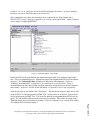
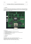
Figure 3: ISP Starter Board
Address Decoding Example
The goal in this example is to address decode and memory map an I/O device to the addresses
8000H – 8001H. Without the use of a PLD this decoding circuit requires the use of six logic
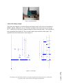
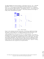
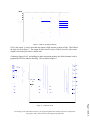
ICs. A DM74LS138 Decoder is simulated using the Lattice schematic editor. This will allow it
to be programmed into the PLD. There are three enable inputs and three select inputs. The
equivalent circuit for the decoder is seen in figure 4.
Figure 4: 3-8 Decoder
Page 7.1059.4
Proceedings of the 2002 American Society for Engineering Education Annual Conference & Exposition
Copyright Ó 2002, American Society for Engineering Education