1
SolarLog800e
Solare Datensysteme GmbH
Stand Juli 2008 – 1.0.0-7 | Art.Nr. 250003
1
Photovoltaic System Monitoring
SolarLog800e
Installation Manual
2
Solare Datensysteme GmbH
SolarLog800e
Table of Contents
Introduction........................................................................................................................5
Delivery Scope.........................................................................................................................8
Terminal Block Plugs.........................................................................................................12
Special RS485-Piggyback (Manufacturer: Solare Datensysteme GmbH)..........................14
Important Installation Information................................................................................ 14
Installation....................................................................................................................15
Connection Diagram.............................................................................................15
Step 2.......................................................................................................................17
Step 3.......................................................................................................................17
Step 4.......................................................................................................................18
Mixed Operation Mode: Special RS485 Piggyback and Original SMA Piggyback......... 18
Original SMA RS485 Piggyback (Manufacturer: SMA)..................................................... 18
Kaco – Powador / PVI-BluePlanet with RS485 Interface......................................................20
Powador........................................................................................................................20
PVI-BluePlanet.............................................................................................................. 20
Cabling.........................................................................................................................20
Terminal Block – Powador – Models:..............................................................................20
Terminal Block – PVI-BluePlanet – Models:.................................................................... 22
SolarMax – Series S, C and E with RS485 Interface............................................................. 22
S and C Series...............................................................................................................23
Cx Series.......................................................................................................................23
E Series.........................................................................................................................23
Cabling.........................................................................................................................23
Fronius – IG15-60 (HV) and IG35/50PLus with ComCard...................................................25
Fronius ComCard Installation .......................................................................................25
Communication Address...............................................................................................25
Cabling.........................................................................................................................25
Kyocera Inverters...............................................................................................................27
RS485 Interface.............................................................................................................27
Cabling.........................................................................................................................27
Mitsubishi with RS485 Interface.........................................................................................28
Cabling.........................................................................................................................28
Power-One/Aurora with RS485 Interface...........................................................................30
Cabling.....................................................................................................................30
Terminal Block – Outdoor Models:.................................................................................30
Sunways – NT with RS485 Interface................................................................................... 31
Terminal Block – 750V Models:..................................................................................... 31
Terminal Block – 850V Models:..................................................................................... 31
Vaillant – auroPOWER VPI /1 and VPI with RS485 Interface.................................................32
Vaillant - auroPOWER VPI /1......................................................................................... 32
SolarLog800e
Solare Datensysteme GmbH
3
Vaillant – auroPOWER VPI.............................................................................................. 32
Cabling.........................................................................................................................32
Solutronic with RS485 Interface.........................................................................................34
Cabling.........................................................................................................................34
Schüco SGI Series with RS485 Interface............................................................................. 35
Cabling.........................................................................................................................35
REFUSOL with RS485 Interface...........................................................................................36
Cabling.........................................................................................................................36
Kostal Pico / Solar-Fabrik Convert T with RS485 Interface.................................................37
Cabling.........................................................................................................................38
Multistring Technology................................................................................................. 38
Mastervolt with RS485 Interface........................................................................................ 38
Cabling.........................................................................................................................39
Suntension (Sunville) / Phoenixtec with RS485 Interface....................................................39
Cabling.........................................................................................................................40
SolarLog800e Modem Kit Delivery Scope...........................................................................41
SolarLog800e Mobile Phone Kit Connection ..........................................................................42
SolarLog800e Mobile Phone Kit.........................................................................................42
SMA SensorBox Connection...................................................................................................43
Cabling.............................................................................................................................43
Additional Sensors........................................................................................................44
Initial Startup.................................................................................................................... 44
External Electric Meter Connection........................................................................................ 45
RS485 Cabling...................................................................................................................46
S0 Output Cabling.............................................................................................................47
Current-Controlled S0 Output.......................................................................................47
Contact-Controlled S0 Output...................................................................................... 47
Pulse Factor..................................................................................................................47
Connecting Relays.................................................................................................................49
Alarm Contact Connection.....................................................................................................50
Connecting to the Computer/Network...................................................................................51
Technical Data.......................................................................................................................52
Internet Ports....................................................................................................................52
Timer................................................................................................................................53
CE Conformity Declaration................................................................................................ 54
Change History......................................................................................................................55
4
Solare Datensysteme GmbH
SolarLog800e
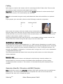
Introduction
The SolarLog800e unit represents the latest generation of the SolarLog series. Based on the
web technology of the previous devices, many customer wishes and suggestions were
implemented in this new model.
The first part of the installation manual describes the delivery scope and installation of the
SolarLog800e. This is followed by a description of the cabling and connection to the inverters
as well as additional accessories.
The initial startup and operation of the touch screen display is explained in the user manual.
SolarLog800e
Solare Datensysteme GmbH
5
Safety Notes
Read the following safety notes before the initial startup of the equipment.
Our products have been inspected at the factory and are free of technical defects when
being shipped.
To maintain this state, compliance with the content of these safety notes and the type
plates attached to the equipment, as well as all other stickers, labels, and safety information
is required when handling the device (transport, storage, installation, initial startup,
operation, maintenance, putting out of operation).
These safety notes are valid in the Federal Republic of Germany. When used in other
countries, comply with the applicable local rules and regulations.
If the information contained in these safety notes is insufficient, please contact the
manufacturer for additional information.
Prior to unpacking the equipment, check whether the packaging is intact. Verify that the
delivery is complete upon unpacking the equipment and immediately report any detected
damages to the shipping company.
Before the initial startup, make sure the power pack is in perfect order. If in doubt, consult
an electrician or contact the address listed at the end of the manual.
Before the initial startup, please check to make sure the line voltage of the equipment
matches the power supply of your country.
Only operate the equipment with the power pack included in the delivery scope.
Condensation may form if the power pack is quickly moved from a cold to a warm
environment. Wait until the power pack has become acclimated. Do not operate equipment
when condensation is detected! Danger to limb and life!
All repairs must be carried out by authorized service personnel. Please contact the address
listed at the end of the manual.
Check the power plug/power pack regularly for damage. In case of damage, do not use
plug/power pack and replace.
The equipment is not suitable for outdoor use.
Before cleaning: Switch off mains power supply. Use a light cleaner and a slightly moist
6
Solare Datensysteme GmbH
SolarLog800e
cloth to clean the equipment. Never clean under running water or allow moisture to
penetrate the equipment!
Additional notes:
The SolarLog800e is operated with 12V DC. Operating the equipment with any other
operating voltage will void the warranty. Please use only the included power pack.
The SolarLog800e is protected with IP20 and suitable only for installation in a dry, dust-free
interior room.
The max. load of the relay is 24V DC and 5A.
Before establishing any type of cable connection between the SolarLog800e and inverter, all
inverters must be de-energized, i.e. the AC side must be disconnected first followed by the
DC side. Please wait at least 5 minutes until the capacitors of the inverters have become
discharged.
SolarLog800e
Solare Datensysteme GmbH
7
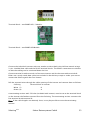
Delivery Scope
The SolarLog800e is delivered with the following components:
1.
SolarLog800e basic unit
2.
12V AC power adapter
3.
Manual
4.
Terminal block plug for all connections (except CAN): 2x3-pin, 1x4-pin, 2x6-pin
5.
4x anchors and screws for mounting to wall
To connect to the computer or network, you still need a network cable (RJ45, CAT5 or CAT6)
in the corresponding length.
You also need suitable cables to connect the inverters with one another.
Suitable, prefinished cables for the respective inverter manufacturers are available as optional
equipment. The cable sets have a length of 3 meters.
8
Solare Datensysteme GmbH
SolarLog800e
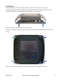
Installation
The SolarLog800e must be installed indoors. Avoid direct exposure to sunlight.
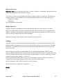
The unit is fastened to the wall with four fixing points in the rear of the case. The silvercolored side panels can be removed for this purpose. Press onto the
two fixing points and pull side panels up and off.
Now you can attach the SolarLog800e using the corresponding drilled holes and included
screws.
Then reattach both side panels (apply slight pressure until snapped into place).
SolarLog800e
Solare Datensysteme GmbH
9
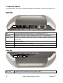
Connection Options
The SolarLog800e has various connection options at the bottom and upper side of the case.
Bottom side:
PIN
1
4
3 1
1
6
Rel.
Relays for switching external signals, e.g. flashing beacon, etc.
RS485A
First RS485 interface. Connect inverters, sensor box, or large display.
RS485/422B
Second RS485 interface (RS422 for Fronius). Connect inverters, sensor box, or
large display.
Power 12V
12 volt DC input
Network
Ethernet network port (10/100 Mbit)
RS232
RS232 modem port. Connect an analog or GPRS modem.
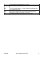
Upper side:
PIN
S0 In/Out
10
6
11 3
1
S0 pulse input to connect to external power meter.
Solare Datensysteme GmbH
SolarLog800e
S0 pulse output to connect to external large display.
Alarm
Connect an anti-theft contact loop.
With “bell wire” up to 1000m.
Can
Can bus, for future expansions. Currently not used. A terminal block plug is
USB
USB host port. Suitable for USB memory sticks with capacity up to 2 GB
not included for this socket.
(important: not suitable for connecting to computer!)
Reset
SolarLog800e
Reset button. Restarts the SolarLog800e; does not reset data.
Solare Datensysteme GmbH
11
Inverter Connection
Since the SolarLog800e must communicate directly with each individual inverter, the
corresponding data cables are required. Green terminal block plugs are enclosed for the
SolarLog800e and the first inverter connection.
Note: Suitable, prefinished cable sets for the respective inverter manufacturers are available
as optional equipment.
Since each inverter manufacturer uses different types of cables and connectors, the
corresponding data cables must be adjusted correctly. The following chapter describes the
connection configurations for all supported manufacturers.
Note: Always comply with the specific instructions of each manufacturer for connecting the
data cables. These instructions are listed in the corresponding manufacturer documentations.
Terminal Block Plugs
The SolarLog800e has two RS485 interfaces, one marked “A” and the other “B.” Interface “B”
can also be used as an RS422 interface (for Fronius PI).
RS485A:
4-pin green connector
RS485/422B: 6-pin green connector
1
4
1
4 6
The numbering of the connectors is from left to right, from 1 to 4 or 6.
The assignment of the connectors is as follows:
Pin
RS485A
RS485B
RS422 (Fronius)
1
Data+
Data+
TX+
3
Ground
2
4
5
6
12V
Data-
12V
Data-
12V
Ground
TX-
Ground
RX+
RX-
This means that the first 4 pins of the RS485/422B socket are wired the same as the RS485A
socket.
12
Solare Datensysteme GmbH
SolarLog800e
Note: The terms “Data+” / “Data-" are manufacturer-specific. Sometimes this is also
described as "A" and "B" or other combinations. Please comply exactly with the description in
this manual or the inverters are later not detected properly.
A 4-pin wired plug can also be plugged left-aligned into the 6-pin socket.
Caution: Damage to the SolarLog800e and interface boards may result if plugged in not leftaligned.
SolarLog800e
Solare Datensysteme GmbH
13
SMA
Very important:
SMA inverters can be connected in two different ways depending on which RS485 piggyback
was installed.
IMPORTANT – Different Cabling!
Original SMA RS485 PIGGYBACK:
3-pin cabling
Special RS485 PIGGYBACK:
4-pin cabling
Important note: Never open the case of the inverter if inverter is energized. Please observe the
notes and instructions in the SMA manual.
Special RS485-Piggyback (Manufacturer: Solare Datensysteme GmbH)
Note: This requires 4-pin cabling!
The special piggyback is a simple “dumb” RS485 interface converter without controller. The
simple and robust design eliminates any interference. The technical data and properties of the
PI remain intact if properly installed in compliance with the installation instructions. The
piggyback is indirect-coupled and has a 6.5 kV insulation protection. Each piggyback is
individually subjected to a complete function test on a SMA inverter.
Note: The special piggyback may only be used in conjunction with the SolarLog800e.
The special RS485 piggybacks are compatible with the following inverter types:
−
SB-SunnyBoy (but not SB-4000/5000TL-20 NextGeneration; these require the original
SMA RS485 module)
−
−
SMC-SunnyMiniCentral
SWR (model year 2001 and later). The display may have to be disassembled for installing
the piggyback. However, this “space problem” also exists with the original SMA
piggybacks.
Please check the completeness of the included accessories:
1 insulating sleeve for data line
1 jumper
1 screw connection/ bushing PI-PG 16 (M22)
1 flat pin cross connector for connection on case/ground
Important Installation Information
The PIs must be opened to install the piggyback interface boards. Only authorized trained
personnel may perform this installation. Please comply with the instructions of the inverter
14
Solare Datensysteme GmbH
SolarLog800e
manual.
Installation
The mains power supply connection must be severed before performing any work on the
inverter. This requires disconnecting the inverter first from the AC side and then from the DC
side. Please wait at least 30 minutes until all current-carrying components have become
discharged.
Please also note that the inverter and the interface board include sensitive electronic
components that may become damaged by static discharges.
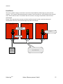
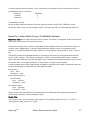
Connection Diagram
SMA-WR1
SMA-WR2
SMA-WRx
Special piggyback
SolarLog400e
Set jumper
Insulation sleeve
SolarLog
SolarLog800e
4-pin, shielded cable
Solare Datensysteme GmbH
15
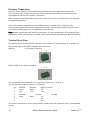
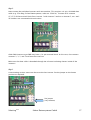
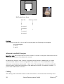
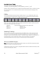
Step 1
First, set the piggyback on the control board in the inverter. Make sure that the printed text
“bottom” can be seen on the bottom left of the board (see Fig. 2 below). Note: The lower pin
connector must be installed left-aligned.
(1) Control board without piggyback
Install
piggyback
here
(2) Control board with piggyback
Text
“bottom“
16
Solare Datensysteme GmbH
SolarLog800e
Step 2
Now connect the individual inverters with one another. This requires a 4-pin, shielded data
cable (e.g. 25m Ring, Solare Datensysteme, order no. 220014). Connect all 4 contacts
(2,3,5,7) of the terminal block from inverter 1 with inverter 2 and on to inverter 3, etc. until
all inverters are connected with each other.
Older SMA inverters type SWR may have a 10-pin terminal block. In this case, also connect
contacts 2, 3, 5, and 7 and leave the rest free.
Make sure the data cable is threaded through the silicone insulating sleeves inside of the
inverters.
Step 3
A terminating resistor must now be set at the last inverter. Set the jumper to the lowest
position as depicted.
Conn. block
Contacts
2,3,5,7
Set jumper
(very bottom)
SolarLog800e
Solare Datensysteme GmbH
17
The middle and top position must remain free!
Step 4
Now connect the first inverter with the SolarLog800e.
Either use a ready-made data cable (not included in the delivery scope) or make your own.
Pull the exposed wires through the cable opening of the inverter and connect them as follows:
SolarLog
White (1)
Yellow (2)
Green (3)
Brown (4)
Terminal block in inverter
2
3
5
7
Pull the data cable through the included insulation sleeve. Connect terminal block 5 of the
inverter with the included flat cable plug to the inverter case.
This concludes the hardware installation. Now reclose and operate the inverter.
Mixed Operation Mode: Special RS485 Piggyback and Original SMA Piggyback
The special RS485 piggyback and the original SMA piggyback can also be used in a mixed
operation mode. This also requires a 4-wire cable connection. However, terminal 2 (yellow
SolarLog) may not be connected to terminal 3 (inverter with original piggyback)!
Original SMA RS485 Piggyback (Manufacturer: SMA)
Note: This requires 3-pin cabling!
The installation is described in detail in the piggyback manual by SMA included with the
interface board. The cabling of the inverters with one another is described on page "6 of 8"
under "Cabling a SB / SWR to a computer via RS485." Connect the individual inverters with one
another as described in the SMA manual using a 3-pin, shielded data cable.
Then set jumper A on the piggyback of the last inverter as described on page “5 of 8” and
page “6 of 8” in the SMA manual.
Either use a ready-made data cable (not included in the delivery scope) or make your own to
connect the SolarLog with the first inverter.
Pull the exposed wires through the cable opening of the inverter and connect them as follows:
SolarLog
White (1)
Green (3)
Brown (4)
18
Terminal block in inverter
2
5
7
Solare Datensysteme GmbH
SolarLog800e
Pull the data cable through the included insulation sleeve. Connect terminal block 5 of the
inverter with the included flat cable plug to the inverter case.
This concludes the hardware installation. Now reclose and operate the inverter.
SolarLog800e
Solare Datensysteme GmbH
19
Kaco – Powador / PVI-BluePlanet with RS485 Interface
Important note: Never open the case of the inverter if inverter is energized. Please observe the
notes and instructions in the Kaco manual.
Powador
All Powador models have a factory-integrated RS485 interface. However, the interface must
be activated via the control display. Additionally, a unique communication address must be
assigned to each inverter. It is recommended to assign addresses consecutively starting with
1, then 2, etc. This setting is also carried out with the control display. Follow the instructions
of the Kaco manual.
Kaco central inverters are depicted as 3 independent inverters in the SolarLog display. For
example, if two central inverters are installed and assigned the RS485 address 1 and 2,
respectively, the SolarLog depicts 6 inverters.
PVI-BluePlanet
The PVI-BluePlanet models were shipped up until approx. the middle of 2005 and are
equipped with a RS232 or RS485 option at the factory. The RS485 option is required for
operation with the SolarLog800e. Retrofitting the interface is done by the company Kaco.
Please ask your installer or contact Kaco directly.
A unique communication address must be assigned to each inverter. Assignment takes place
with a DIP switch inside of the inverter. Please follow the instructions of the Kaco manual. It is
recommended to assign addresses consecutively starting with 0, then 1, then 2, etc.
Note: If the DIP switch is missing on the control board, then the PVI-BluePlanet is the RS232
model.
Cabling
The cabling of the individual inverters is carried out with terminal blocks located inside of the
device.
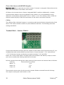
Terminal Block – Powador – Models:
Powador approx. up to model year 06/2007
20
Solare Datensysteme GmbH
SolarLog800e
Powador approx. starting with model year 06/2007 (terminate via DIP switch)
Powador 8000xi (6400xi/7200xi):
The 8000xi models are unique when it comes to cabling since three 8000xi units can be
linked into one group. However, it is also possible to use one or two units without grouping
them. Cabling is completely different depending on configuration. Detailed instructions are
also listed in the Kaco inverter installation manual.
8000xi, grouped:
•
This requires that one of the three inverters is jumpered as “master” and the remaining
two as “slaves.”
•
The data cable of the SolarLog is connected to the terminal block "LOGGER” of the
“master” inverter.
•
The three inverters are additionally connected with one another using the terminal block
"SYM.”
•
All three converters must be assigned a consecutive RS485 address configurable on the
display of the inverters.
•
Switch “SYM-Bus” to active on the inverter display.
8000xi, individually:
•
•
Jumper inverters to "slave.”
The data cable of the SolarLog is connected to the terminal block "SYM” of the “slave”
inverters.
•
All converters must be assigned a consecutive RS485 address configurable on the display
of the inverters.
•
Switch “SYM-Bus” to inactive on the inverter display.
SolarLog800e
Solare Datensysteme GmbH
21
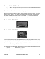
Terminal Block – PVI-BluePlanet – Models:
Connect the individual inverters with one another as described in the Kaco manual using a 2pin, shielded data cable and the RS485 terminal blocks. The RS485 connections are double so
that the cabling can be continued down the line.
Connect terminal A with terminal A of the next inverter and do the same with terminals B.
Either use a ready-made data cable (not included in the delivery scope) or make your own to
connect the SolarLog with the first inverter.
Pull the exposed wires through the cable opening of the inverter and connect them as follows:
SolarLog
Terminal block in inverter
White (1)
Brown (4)
B
A
BluePlanet / Serial- Powador:
A terminating resistor with 330 ohm (included with inverter) must be set at the terminal block
on the inverter the farthest removed from the SolarLog. The terminating resistor connects the
free terminal A with terminal B.
Series2-Powador:
A terminating resistor must be set with the inside DIP switch (see Fig. at top) at the inverter
the farthest removed from the SolarLog. Please make sure the DIP switches of the other
inverters are set to the “OFF” position, otherwise the data communication will be flawed.
Note: If the cable lengths are relatively short, it may be possible to omit the terminating
resistor.
SolarMax – Series S, C and E with RS485 Interface
Important note: Never open the case of the inverter if inverter is energized. Please observe the
notes and instructions in the Sputnik/SolarMax manual.
22
Solare Datensysteme GmbH
SolarLog800e
S and C Series
All S/C series models have a factory-integrated RS485 interface. A unique communication
address must be assigned to each inverter. It is recommended to assign addresses
consecutively starting with 1, then 2, etc. This setting is also carried out with the control
display. Follow the instructions of the SolarMax manual.
S Series: Please note that only the RS485 interface is activated on the inverter display (preset
at the factory) and not the - integrated - Ethernet interface.
Note: The factory setting of the inverter address is 255, which is not a valid address number.
For example, even if only 1 inverter is connected to the SolarLog, the communication address
must be set manually to “1.”
Cx Series
The Cx series models do not have an integrated RS485 interface and must be retrofitted. In
this case, please contact your installer or the manufacturer.
E Series
The E series models do not have an integrated communication interface and must be
retrofitted with a corresponding interface before connecting the SolarLog.
Please follow the installation instructions included with the purchased interface. Make sure
the RS485/RS232 jumper and terminating resistor are set correctly on the interface board (see
interface board manual).
A unique communication address must be assigned to each inverter. It is recommended to
assign addresses consecutively starting with 1, then 2, etc. This setting is also carried out
with the control display. Follow the instructions of the SolarMax manual.
Cabling
RJ45 plugs are used on the inverter side for connecting the RS485 data cable. These are the
same plugs as with commonly used network patch cables.
Important! The SolarLog also has a RJ45 socket. Do not connect this socket with the RJ45
plugs of the inverter. This could destroy the SolarLog.
Note: We recommend using the ready-made SolarMax data cable available as an optional part.
If you prepare your own cable, please use the following connection assignment:
SolarLog800e
Solare Datensysteme GmbH
23
RJ45 plug from front
RJ45 Pin
SolarLog RS485
1
2
3
3
2
2
4
3
5-unused
6-unused
7
1
8
4
The cabling of the individual inverters with one another is carried out with commonly used
network cables equipped with a RJ45 plug.
SolarMax S/C Series:
Cabling can be done at any time since the invertors do not have to be opened.
The two RJ45 socket for the system communication are located on the bottom side of the
unit. Plug one plug of the cable into any one of the sockets of the first inverter. Plug the other
plug of the cable into any one of the sockets of the second inverter. Continue connecting
inverter number 2 with inverter number 3, and so on.
Now plug the ready-made SolarLog data cable with the RJ45 plug into the last free socket of
the last inverter.
SolarMax E Series:
De-energize inverter or wait until evening (data for setting the communication address
entered into the display must be done during the daytime).
Since the RJ45 connection sockets are inside of the inverter on the interface board, the
network cables must be threaded through the cable feedthrough on the bottom of the unit.
Except for the first inverter, always two cables are pulled through: one cable from the
previous PI and one cable to the next PI or to the SolarLog. Plug the cable from the previous PI
into the left socket labeled “RS485 in” and the cable to the next PI into the right socket
labeled “RS485 out.”
24
Solare Datensysteme GmbH
SolarLog800e
Now plug the ready-made SolarLog data cable with the RJ45 plug into the last free socket of
the last inverter.
Fronius – IG15-60 (HV) and IG35/50PLus with ComCard
Important note: Never open the case of the inverter if inverter is energized. Please observe the
notes and instructions in the Fronius manual.
Before the SolarLog800e can be connected to the inverter, an interface board, a so-called
“ComCard,” must be installed.
Fronius ComCard Installation
The ComCard may be already installed at the factory or may have to be installed subsequently
as a "ComCard retrofit."
Note: The inverter must be opened for the installation. Please follow the instructions of the
Fronius IG manual of your inverter!
The installation of the ComCard is described in detail in the inverter manual; please follow all
instructions included in the manual.
We recommend leaving one slot free between the installed ENS card and the ComCard.
Communication Address
A unique communication address must be assigned to each inverter. It is recommended to
assign addresses consecutively starting with 1, then 2, etc. This setting is also carried out
with the control display. Follow the instructions of the Fronius manual, chapter "Operating
Concept," section "The Setup Menu."
Cabling
The cabling of the individual inverters with one another is carried out with commonly used
network cables equipped with a RJ45 plug.
Each ComCard has two RJ45 sockets labeled "IN” and “OUT.” It is very important to adhere
with the correct sequence of cabling to prevent flawed data transfers.
Important! The SolarLog also has a RJ45 socket. Do not connect this socket with the RJ45
plugs of the inverter. This could destroy the SolarLog.
Since Fronius devices use an RS422 interface, only the 6-pin RS422B connection can be used
on the SolarLog side.
SolarLog800e
Solare Datensysteme GmbH
25
Note: We recommend using the ready-made Fronius data cable available as an optional part.
An endplug is included with the cable set (which is not a terminal resistor!).
If you prepare your own cable, please use the following connection assignment:
RS422B:
6
1
RJ45 Pin
1
SolarLog RS422B (6-pin)
-
2
-
4
1
6
6
8
-
3
5
7
5
4
-
Endplug:
The endplug consists of an 8-pin RJ45 blind plug with the following wires bridged:
RJ45 PIN bridged
3 and 4
5 and 6
Using the ready-made cable with the 6-pin plug to connect the SolarLog RS422B with the “IN”
socket of the first inverter.
Now connect all inverters as follows: PI1-OUT with PI2-IN, PI2-OUT with PI3-IN, etc.
Use the endplug on the OUT socket of the last inverter.
Note: LED-E on the SolarLog indicates the communication status. As soon as all cables are
connected correctly and the inverters are active, the red LED goes out.
26
Solare Datensysteme GmbH
SolarLog800e
Kyocera Inverters
Important note: Never open the case of the inverter if inverter is energized. Please observe the
notes and instructions in the Kyocera manual.
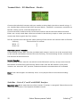
The Kyocera inverters are manufactured by the company Danfoss/PowerLynx. The following
inverters with the same design also have the same data protocol and can be used as well:
−
Solarworld SunPlug
−
PowerStocc
The used interfaces may differ.
RS485 Interface
A RS485 interface is needed to monitor data with the SolarLog. This interface has been
factory-installed into all inverters starting Feb. 2007. Previous models were equipped with a
RS485 or wireless radio interface. However, the latter cannot be used for the SolarLog. In this
case, the RS485 interface and must be retrofitted.
Additional settings on the display of the inverter are not necessary.
Cabling
The cabling of the individual inverters with one another is carried out with commonly used
network cables equipped with a RJ45 plug. The two RJ45 sockets are located under the right
side cover panel that can be unscrewed and removed. Please follow the instructions in the
Kyocera manual.
Now connect all inverters with one another using commercially available network cables.
Plug one plug of the cable into any one of the sockets of the first inverter. Plug the other plug
of the cable into any one of the sockets of the second inverter. Continue connecting inverter
number 2 with inverter number 3, and so on.
Now plug the Kyocera data cable (accessory, not included in delivery scope) into the free
socket of the first inverter using the RJ45 plug or the self-made cable.
Use the endplug on the still free socket of the last inverter.
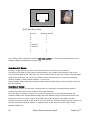
Kyocera/PowerLynx connection assignment:
RS485:
SolarLog800e
Solare Datensysteme GmbH
27
8
1
RJ45 plug from front
RJ45 Pin
SolarLog RS485
1
3
3
4
2
3
4-unused
5-unused
6
1
7-unused
8-unused
Endplug:
The endplug consists of an 8-pin RJ45 blind plug with the following wires bridged:
RJ45 PIN bridged
3 and 4
5 and 6
Mitsubishi with RS485 Interface
Important note: Never open the case of the inverter if inverter is energized. Please observe the
notes and instructions in the Mitsubishi manual.
All Mitsubishi inverters have a factory-integrated RS485 interface. Additionally, a unique
communication address must be assigned to each inverter. It is recommended to assign
addresses consecutively starting with 1, then 2, etc. This setting is also carried out with the
control display. Follow the instructions of the Mitsubishi manual. (The address number 1 is
preset with all Mitsubishi inverters.)
Cabling
The cabling of the individual inverters with one another is carried out with commonly used
28
Solare Datensysteme GmbH
SolarLog800e
telephone cables equipped with a RJ11 plug. RJ11 plugs are 6-pin but usually only the middle
4 pins are used, which is sufficient. It is important, however, that the 4 (or 6) pins are looped
through 1 to 1.
The two RJ11 sockets are located on the left bottom side inside of the inverter. This means
the front panel of the inverter must be unscrewed and removed for the installation. Please
follow the instructions in the Mitsubishi manual.
Now connect all inverters with one another using the RJ11 cables.
Plug one plug of the cable into any one of the sockets of the first inverter. Plug the other plug
of the cable into any one of the sockets of the second inverter. Continue connecting inverter
number 2 with inverter number 3, and so on. Set the DIP switch for the terminal resistor of
the last inverter to “ON.”
Either use a ready-made data cable (not included in the delivery scope) to connect the
SolarLog and the first inverter or make your own following these steps:
Mitsubishi connection assignment:
RS485:
RJ11 Pin
SolarLog
3
1
4
SolarLog800e
4
Solare Datensysteme GmbH
29
Power-One/Aurora with RS485 Interface
Important note: Never open the case of the inverter if inverter is energized. Please observe the
notes and instructions in the Power-One manual.
All Power-One inverters have a factory-integrated RS485 interface. Additionally, a unique
communication address must be assigned to each inverter. It is recommended to assign
addresses consecutively starting with 2 (not 1!, then 2, 3, etc. This setting is also carried out
with the control display. Follow the instructions of the Power-One/Aurora manual.
Cabling
The cabling of the individual inverters is carried out with terminal blocks located inside of the
device. The indoor/outdoor models may have different interfaces. The following describes
cabling with RS485.
Terminal Block – Outdoor Models:
Connect the individual inverters with one another as described in the PI manual using a 3-pin,
shielded data cable and the RS485 terminal blocks. Connect terminal "+T/R” with terminal
“+T/R” of the next inverter and do the same with terminals “T/R” and “RTN.”
Either use a ready-made Power-One data cable (not included in the delivery scope) or make
your own to connect the SolarLog with the first inverter.
Pull the exposed wires through the cable opening of the inverter and connect them as follows:
SolarLog
White (1)
Brown (4)
Green (3)
Terminal block in inverter
+T/R
-T/R
RTN
The terminal resistor must also be set at the inverter farthest removed from the SolarLog.
This requires setting the small switch to “ON."
30
Solare Datensysteme GmbH
SolarLog800e
Sunways – NT with RS485 Interface
Important note: Never open the case of the inverter if inverter is energized. Please observe the
notes and instructions in the Sunways manual.
The new Sunways AT models are currently not fully supported.
Make sure to configure a different internal address for every Sunways NT inverter. The factory
setting is always address 1. The address configuration is described in the Sunways manual
and can be adjusted via the control display of the inverter. It is recommended to assign
addresses consecutively starting with 1, then 2, then 3, etc.-{}-
Terminal Block – 750V Models:
Terminal Block – 850V Models:
Connect the individual inverters with one another as described in the Sunways manual using a
2-pin, shielded data cable and the RS485 terminal blocks. The RS485 connections are double
so that the cabling can be continued down the line.
Either use a ready-made Sunways data cable (not included in the delivery scope) or make your
own to connect the SolarLog with the first inverter.
Pull the exposed wires through the cable opening of the inverter and connect them as follows:
SolarLog
White (1)
Brown (4)
SolarLog800e
Terminal block in inverter
RS485+
RS485-
Solare Datensysteme GmbH
31
The jumper JP must be set at the inverter farthest removed from the SolarLog. Do not set this
jumper on the other inverters.
Vaillant – auroPOWER VPI /1 and VPI with RS485 Interface
Important note: Never open the case of the inverter if inverter is energized. Please observe the
notes and instructions in the Vaillant manual.
Vaillant - auroPOWER VPI /1
All auroPOWER VPI /1 models have a factory-integrated RS485 interface. However, the
interface must be activated via the control display. Additionally, a unique communication
address must be assigned to each inverter. It is recommended to assign addresses
consecutively starting with 1, then 2, etc. This setting is also carried out with the control
display. Follow the instructions of the Vaillant manual.
Vaillant – auroPOWER VPI
The auroPOWER VPI models were shipped up until approx. the middle of 2005 and are
factory-equipped with a RS232 option. The RS485 option is required for operation with the
SolarLog800e. Retrofitting the interface is done by the company Vaillant. Please ask your
installer or contact Vaillant directly.
A unique communication address must be assigned to each inverter. Assignment is carried
out with the inverter menu for units with transformer. Assignment is carried out with a DIP
switch inside of the inverter for units without transformer. Please follow the instructions of
the Vaillant manual. It is recommended to assign addresses consecutively starting with 0,
then 1, then 2, etc.
Note: If the RS 485 interface is missing on the control board, then the auroPOWER VPI inverter
is the RS232 model.
Cabling
The cabling of the individual inverters is carried out with terminal blocks located inside of the
device.
De-energize inverter or wait until evening (data for setting the communication address
entered into the display must be done during the daytime).
Terminal Block – auroPOWER VPI xx00 /2 Models:
32
Solare Datensysteme GmbH
SolarLog800e
Terminal Block – auroPOWER VPI /1 Models:
Terminal Block – auroPOWER VPI Models:
Connect the individual inverters with one another as described in the Vaillant manual using a
2-pin, shielded data cable and the RS485 terminal blocks. The RS485 connections are double
so that the cabling can be continued down the line.
Connect terminal A with terminal A of the next inverter and do the same with terminals B.
Either use a ready-made data cable (not included in the delivery scope) or make your own to
connect the SolarLog with the first inverter.
Pull the exposed wires through the cable opening of the inverter and connect them as follows:
SolarLog
White (1)
Terminal block in inverter
Brown (4)
B
A
A terminating resistor with 330 ohm (included with inverter) must be set at the terminal block
on the inverter the farthest removed from the SolarLog. The terminating resistor connects the
free terminal A with terminal B.
Note: If the cable lengths are relatively short, it may be possible to omit the terminating
resistor.
SolarLog800e
Solare Datensysteme GmbH
33
Note: Starting with inverter generation VPI xx00 /2, the 330 Ohm resistance is activated with
a DIP switch as needed. On delivery, the terminal resistor is activated. This applies currently
only to units without transformer.
Solutronic with RS485 Interface
Important note: Never open the case of the inverter if inverter is energized. Please observe the
notes and instructions in the Solutronic manual.
Prerequisite: All inverters must have firmware version 1.2.39 or later. Please visit
www.solutronic.de for the current firmware versions and information about how to apply the
firmware to the inverter.
All Solutronic inverters have a factory-integrated RS485 interface (connection socket X2).
Additionally, a unique communication address must be assigned to each inverter. It is
recommended to assign addresses consecutively starting with 1, then 2, etc. This setting is
also carried out with the control display (parameter 164). Furthermore, parameter 265 is used
to set the COM interface to “Protocol 9 – SolarLog.”
Follow the instructions of the Solutronic manual.
Cabling
Connect the individual inverters with one another using a 3-pin, shielded data cable and the
X2 connection socket of the inverters:
Either use a ready-made data cable (not included in the delivery scope) or make your own to
connect the SolarLog with the first inverter.
SolarLog
Terminal connector on inverter (from left to right)
White (1)
Pin 1 RS485A
Brown (4)
Pin 2 RS485B
Green (3)
34
Pin 3 GND
Solare Datensysteme GmbH
SolarLog800e
Schüco SGI Series with RS485 Interface
Important note: Never open the case of the inverter if inverter is energized. Please observe the
notes and instructions in the Schüco manual.
All Schüco models have a factory-integrated RS485 interface. A unique communication
address must be assigned to each inverter. It is recommended to assign addresses
consecutively starting with 1, then 2, etc. This setting is also carried out with the control
display. Follow the instructions of the Schüco manual.
Cabling
The cabling of the individual inverters with one another is carried out with commonly used
network cables equipped with a RJ45 plug. Schüco uses special IP65-compatible network
plugs required for outdoor use. If the inverters are installed indoors, it is also possible to use
regular network cables.
The IP20 data cable included with the SolarLog is designed only for indoor use.
Schüco Pin
(RJ45 plug)
3 (A)
6 (B)
SolarLog Pin
(4-pin green plug)
4
1
RJ45 plug
Front view
View from rear
Now connect all Schüco inverters with one another using commercially available network
cables. The two RJ45 sockets for the system communication are located on the bottom side of
the unit. Plug one plug of the cable into any one of the sockets of the first inverter. Plug the
other plug of the cable into any one of the sockets of the second inverter. Continue
connecting inverter number 2 with inverter number 3, and so on.
Either use a ready-made data cable (not included in the delivery scope) or make your own to
connect the SolarLog with the first inverter.
Now plug the ready-made SolarLog data cable with the RJ45 plug into the last free socket of
the first/last inverter. Plug the endplug (IP20!) onto the other end. In case of cable lengths
less than 100 meters, the endplug is not needed.
SolarLog800e
Solare Datensysteme GmbH
35
REFUSOL with RS485 Interface
Prerequisite: All inverters must have firmware version 800.2.20 or later (check the version in:
Menu F1\Numeric List\Parameters 1.1 to 1.3). Please visit www.refu-elektronik.de for the
current firmware versions and information about how to apply the firmware to the inverter.
All REFU-Elektronik inverters have a factory-integrated RS485 interface (bottom of inverter,
RS485 IN/OUT). Additionally, the SolarLog communication type must be passed to each
inverter and a unique communication address must be assigned to each inverter as well. It is
recommended to assign addresses consecutively starting with 1, then 2, etc. The highest
possible address is 255. These settings are entered on the display of the REFUSOL unit as
follows:
−
Press F1
−
Select “Numeric List,” press ENTER
−
Set parameter number 2000 [password-protected] , press ENTER twice
−
Enter the numbers 72555 and press ENTER
−
Set parameter number 0407, press ENTER
−
Select sub-parameter 0407.3, press ENTER
−
Enter the number 2 (communication type RS485: SolarLog), press ENTER
−
Set parameter number 0406, press ENTER
−
Select sub-parameter 0406.3, press ENTER
−
Enter the numbers xx (address), press ENTER
The port speed must also be set to 9600 baud.
−
Set parameter number 0420, press ENTER.
−
Select sub-parameter 0420.3, press ENTER
−
Enter the numbers 9600 and press ENTER.
Press 2 x ESC to return to performance display.
Cabling
Connect the individual inverters with one another using a 2-pin, shielded data cable and the
RS485 sockets. The RS485 connections are double (IN/OUT) so that the cabling can be
continued down the line. A little plastic bag included with each inverter contains “2 4-pin
SACC-M12MS-4SC plugs.” Now insert one plug into the OUT socket of the one inverter (X14B)
and the other plug into the IN socket (X15B) of the other inverter.
Complete a cable as follows to connect the SolarLog with the first inverter.
36
Solare Datensysteme GmbH
SolarLog800e
Connect the pins on the green 4-pin/6-pin terminal connector of the SolarLog and on the 4pin REFUSOL round connector:
SolarLog
1 (white)
4 (brown)
REFUSOL
2
3
Terminating resistor:
At the inverter farthest removed from the SolarLog at the “RS485 OUT" REFUSOL round
connector, PIN1 must also be bridged to PIN 2 and PIN 3 to PIN 4 to conclude the data bus.
Kostal Pico / Solar-Fabrik Convert T with RS485 Interface
Important note: Never open the case of the inverter if inverter is energized. Please observe the
notes and instructions in the Kostal manual.
All Kostal inverters have a factory-integrated RS485 interface (terminal connectors inside of
inverter case). Additionally, a unique communication address must be assigned to each
inverter. It is recommended to assign addresses consecutively starting with 1, then 2, then 3,
etc.
The RS485 cannot be changed directly on the display but must be configured with the web
server of the inverter. This means a computer must be connected to the PI with a network
cable and the IP address must be changed on the computer accordingly to allow access to the
PI-internal web server (the IP address of the inverter is listed on the display).
A login window opens after entering the IP address. Different user names/passwords must be
entered depending on manufacturer and software status:
Kostal PICO:
User: PICO
Password: pvwr
Solar-Fabrik Convert:
Old firmware:
User: convert
Password: pvwr
Or new firmware:
User: pvserver
Password: pvwr
Please consult the manufacturer documentation for additional information about how to
connect the computer and the network cable.
Kostal Piko:
The process steps are described in the manual “Com_Manual_PIKO_Version_1-21.pdf” or
“Com_Manual_PIKO_Version_2-0.pdf.”
SolarLog800e
Solare Datensysteme GmbH
37
Solar-Fabrik Convert T Models:
The process steps are described in the manual
“Installation_and_Operating_Manual_convert_Netboard__Version_3.1_.pdf.”
However, due to copyright laws, the company Solare Datensysteme GmbH is unable to provide
this documentation. You can download these manuals from the Internet homepage of the
manufacturer.
Cabling
Connect the individual inverters with one another using a 3-pin, shielded data cable at the
10-pin terminal strip of the inverter. The terminal strip is located directly below the display.
Connect terminal 1, 2 and 3 (“A,” “B,” “GND”) with one another.
10
9
8
7
6
5
4
3
2
1
GND
B
A
Either use a ready-made data cable (not included in the delivery scope) or make your own to
connect the SolarLog with the first inverter.
SolarLog
White (1)
Terminal connector on inverter (from right to left).
Terminal 1-A
Green (3)
Terminal 3-GND
Brown (4)
Terminal 2-B
Multistring Technology
The Pico/Convert inverters are equipped with several MPP trackers, which means that each
string input is monitored separately and optimally adjusted to the connected module. The
SolarLog is able to read out the data of up to 3 individual strings; however, this depends on a
possible parallel circuitry inside of the inverter and may be reduced. The SolarLog
automatically detects how many strings are active during the inverter detection.
Mastervolt with RS485 Interface
Note: Installation does not require opening of the inverter case. All of the connection sockets
needed are located on the outside of the case.
All Mastervolt inverters have a factory-integrated RS485 interface located at the bottom of the
case and used with RJ45 sockets.
38
Solare Datensysteme GmbH
SolarLog800e
Cabling
RJ45 plugs are used on the inverter side for connecting the RS485 data cable. These are the
same plugs as with commonly used network patch cables.
Important! The SolarLog also has a RJ45 socket. Do not connect this socket with the RJ45
plugs of the inverter. This could destroy the SolarLog.
Note: We recommend using the ready-made Mastervolt data cable available as an optional
part.
If you prepare your own cable, please use the following connection assignment:
RJ45 Pin
4
SolarLog RS485
3
1
4
Now connect all inverters with one another using commercially available network cables.
Plug one plug of the cable into any one of the sockets of the first inverter. Plug the other plug
of the cable into any one of the sockets of the second inverter. Continue connecting inverter
number 2 with inverter number 3, and so on.
Now plug the Mastervolt data cable (accessory, not included in delivery scope) into the free
socket of the first inverter using the RJ45 plug or the self-made cable.
Multistring Technology
The Mastervolt inverters are equipped with 1 or 2 MPP trackers (depending on model), which
means that each string input is monitored separately and optimally adjusted to the connected
module. Some inverters are also internally divided into 2 or even 3 individual inverters. For
example, the QS6400 is detected as 2 inverters with 2 strings each, a XL15 unit is detected as
3 independent XL5000 units.
The SolarLog automatically detects how many strings and inverters are active during the
inverter detection.
Important note:
The order in which the inverters are displayed in the SolarLog is entirely random. It is
recommended to resort the inverters immediately after the detection process (dialog
"Configuration/Basic/Inverters"). The inverters can be identified by their displayed serial
numbers.
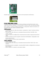
Suntension (Sunville) / Phoenixtec with RS485 Interface
Note: Installation requires an optionally available RS485 data card that must be installed into
each inverter. The inverter does not have to be opened; the card can be inserted at the
bottom of the case and is screwed into place.
SolarLog800e
Solare Datensysteme GmbH
39
Cabling
The RS485 data card on the inverter has 2 x 4 terminal connectors identified with “R+ R- T+
T-.” Connect the individual inverters with one another 1 to 1 using a 4-wire, shielded data
cable.
Note: We recommend using the ready-made Sunville data cable available as an optional part.
If you prepare your own cable, please use the following connection assignment:
SolarLog RS485
RS485 data card
1
R+
(white)
4
R-
(green)
T-
(brown)
T+
(yellow)
Multistring Technology
The Sunville/Phoenixtec inverters are equipped with 1 or 3 MPP trackers (depending on
model), which means that each string input is monitored separately and optimally adjusted to
the connected module.
The SolarLog automatically detects how many strings and inverters are active during the
inverter detection.
Important note:
The order in which the inverters are displayed in the SolarLog is entirely random. It is
recommended to resort the inverters immediately after the detection process (dialog
"Configuration/Basic/Inverters"). The inverters can be identified by their displayed serial
numbers.
40
Solare Datensysteme GmbH
SolarLog800e
SolarLog800e Analog Modem Kit Connection
The analog modem is available in two versions:
1.
2.
Analog home modem
Analog industrial modem
An analog phone connection is needed for using the modem. This is usually possible with
ISDN technology with ISDN phone systems. Please check whether you are able to make a
phone call from your telephone connection. An Internet call-by-call connection is established
for the data connection to the Internet. Some phone system are equipped with a block to
prevent this type of dialing.
If the dialing function of the SolarLog800e is to be used, the corresponding phone number
must be assigned to the used phone socket.
Check the connection with a normal phone if necessary. Make a phone call to an external
phone number and have someone call you.
SolarLog800e Modem Kit Delivery Scope
•
Serial RS232 cable
•
Telephone connection cable
•
Power adapter
Connecting to the SolarLog800e is very easy:
1.
Connect the modem to the RS232 connection on the SolarLog unit using the serial
RS232 cable.
2.
Connect the modem with the telephone cable and plug the cable into the
corresponding phone jack.
3.
Now plug in the power adapter and switch the modem on.
Additional settings are configured with the SolarLog display. A computer is not required.
SolarLog800e
Solare Datensysteme GmbH
41
SolarLog800e Mobile Phone Kit Connection
The mobile phone kit connects the SolarLog800e with the Internet using the mobile phone
network. In addition to the mobile phone kit, a SIM card of the selected mobile phone service
provider is required as well (SIM card not included in delivery scope).
SolarLog800e Mobile Phone Kit
•
Mobile phone modem GPRS
•
Serial RS232 cable
•
Power adapter
•
External antenna with 2-m connection cable
(A mounting rail bracket is available as optional accessory.)
Connecting to the SolarLog800e
1. Insert the SIM card into the modem. Use a pointed object and press hard on the yellow
ejection button on the side of the modem.
2. Screw the external antenna to the modem. Find a suitable location for the magnetic
base antenna with good reception. If needed, check the reception with a mobile phone
first. Good reception is important for a reliable data connection.
3. Connect the modem to the SolarLog800e using the RS232 cable.
4. Plug the RJ11 plug of the power adapter into the modem.
Additional settings are configured with the SolarLog display. A computer is not required.
42
Solare Datensysteme GmbH
SolarLog800e
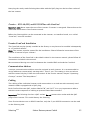
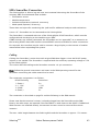
SMA SensorBox Connection
The SolarLog800e is able to log and save environmental data using the SensorBox of the
company SMA. Environmental data includes:
•
Solarization sensor
•
Module temperature
•
Ambient temperature (optional, accessory)
•
Wind speed (optional, accessory)
These data are import for monitoring the yield and for additional analyses and evaluations.
A max. of 1 SensorBox can be connected to the SolarLog800e.
The SensorBox is connected with one of the SolarLog800e RS485 interfaces, which must be
configured with the display to the interface type “SMA.”
If SMA inverters are already connected, the SensorBox can be “appended” as an extension to
the existing RS485 data cable and the second RS485 remains available for other connections.
For example, this interface may be used to connect a large display or the inverter of another
manufacturer when expanding the system.
Cabling
Cabling the SensorBox is easier than with original SMA data loggers since the RS485 power
injector is not needed. The SensorBox is supplied with the necessary operating voltage of 12V
by the SolarLog800e.
This means that the cabling to the SensorBox must be a 4-pin connection.
Note: Follow the general instructions and notes in the SMA operating manual for the
SensorBox concerning the cable material to be used.
The connection assignment is as follows:
RS485 SolarLog
Sensorbox
2 (+12V)
+12V
4 (Data-)
D-
1 (Data+)
3 (GND)
D+
GND
The connection is described on page 54 and the following in the SMA manual.
Please note that the terminal resistor is already plugged into the SensorBox at the SMA
factory. No other steps are required if the SensorBox is used alone on the RS485. If additional
SMA inverters are installed already, the terminal resistors must be removed from these
inverters.
The max. cable length between the SolarLog800e and the SensorBox is approx. 150 meters.
SolarLog800e
Solare Datensysteme GmbH
43
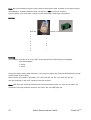
Additional Sensors
Additional sensors can be connected to the SensorBox:
•
Ambient temperature sensor
•
Wind wheel for wind speed
Connecting these types of devices is explained in detail in the SMA SensorBox manual. Please
follow the instructions in the manual.
Initial Startup
The SensorBox is automatically supplied with electricity when switching on the SolarLog800e.
It takes about 1 minute until the SensorBox is then completely initialized.
The SensorBox is integrated into the system with the display dialog “Inverter Detection” the
same any normal inverter.
44
Solare Datensysteme GmbH
SolarLog800e
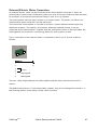
External Electric Meter Connection
An external electric meter can be connected to the SolarLog800e using the S0 input. An
external three-phase meter of the total system can serve as an exact reference measurement,
for example, to provide accurate partial billing in case of co-op systems.
The SolarLog800e lists the meter counter as a virtual inverter. The pulses are offset in an
instantaneous power value (Pac) and the yield sum.
This means the SolarLog800e is also able to monitor a system without connecting to any
additional inverters. This applies, for example, when the installed inverter is not yet
supported by the data protocol. Together with the solarization sensor of the SensorBox, the
SolarLog800e can be used as a monitoring device for such systems as well.
The S0 connection of the external meter is connected to the 6-pin S0-In/Out socket as
follows:
6
1
SolarLog
S0
2
S0-
1
3
4
S0+
bridged
5
Unassigned
6
Unassigned
The max. cable length between the SolarLog800e and the meter should not exceed 10
meters.
The default pulse factor is 1000 pulses/kWh; however, this can be changed for inverter 1 in
the SolarLog display in the dialog “Config./Basic/Inverters.”
SolarLog800e
Solare Datensysteme GmbH
45
Connecting a Large Display
There are basically two different ways to connect large displays to the SolarLog800e:
1. Via RS485
2. Via S0 pulse output
The RS485 is generally preferable but either way is possible. The line lengths with RS485 can
be up to 1000 meters and the data to be depicted can be displayed with the SolarLog800e.
However, when using the S0 output, it is only possible to transfer the current feed-in power
as a pulse string and the display must calculate the power and total yield on its own.
RS485 Cabling
If the RS485 is used for the connection, either one of the RS485 ports of the SolarLog800e
may be used. A large display can be connected two both ports even if inverters are already
connected to the interface(s). Of course, it is preferable to connect the display to an available
RS485 port.
Note: Always follow the manufactures instructions for connecting the display.
Schneider-Displaytechnik:
3-pin control line, 3x0.5mm²
Display
Brown-A
Gray-GND
Blue-B
SolarLog RS485A/B
1
2 (unused)
3
4
RiCo-Electronic:
To connect the RiCo display to the SolarLog via RS485, the display must be used to connect
Pin 1 and 2 on terminal block 3. Please consult the user manual of the display for further
information.
2-pin control line, 2x0.5mm²
Display
SolarLog RS485A/B
Pin1:Data+
1
Pin2:Data-
46
2 (unused)
3 (unused)
4
Solare Datensysteme GmbH
SolarLog800e
S0 Output Cabling
The S0 output can be operated in various configurations, which are active depending on the
wiring of the 6-pin terminal connector.
6
1
Current-Controlled S0 Output
(E.g. displays by Schneider-Displaytechnik)
This connection requires a 2-pin shielded cable, 2x0.6mm², with a maximum length of 100
meters can be used for greater distances.
Always read and comply with the manufacturer information provided by the display
manufacturer.
Display
SolarLog S0 In/Out
S0-
5
S0+
4
bridged
6
Contact-Controlled S0 Output
(E.g. displays by RiCo-Electronic)
This connection requires a 2-pin shielded cable, 2x0.6mm², with a maximum length of 100
meters can be used for greater distances.
Always read and comply with the manufacturer information provided by the display
manufacturer.
Display
SolarLog S0 In/Out
S0-
6
S0+
5
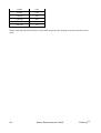
Pulse Factor
By default, the SolarLog800e outputs 1000 pulses/kWh on the S0 output. However, this value
can changed as needed with the SolarLog display in the dialog "Config./Advanced/Large
Display." The pulse factor must be configured in dependency of the system size (kWp).
System size kWp
SolarLog800e
Pulse factor
Solare Datensysteme GmbH
47
30 kWp
2000
60 kWp
1000
100 kWp
600
150 kWp
400
300 kWp
200
600 kWp
100
Please note that the pulse factor in the SolarLog and on the display must be set to the same
value.
48
Solare Datensysteme GmbH
SolarLog800e
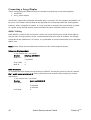
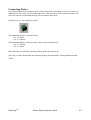
Connecting Relays
The SolarLog800e has a potential-free control relay that is activated in case of an alarm or
malfunction. This relay can be loaded with max. 24V and 5A so that a 220V consumer unit
does not have to be switched directly but via another load relay.
Cabling uses a 3-pin connection plug.
1
3
The following applies in the OFF state:
Pin 1-2 open
Pin 2-3 closed
The following applies in the ON state (active alarm/malfunction):
Pin 1-2 closed
Pin 2-3 open
PIN1 and PIN2 are therefore usually used to switch the load relay.
The relay is easily tested with the SolarLog display and the dialog "Config/Advanced/AntiTheft."
SolarLog800e
Solare Datensysteme GmbH
49
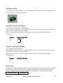
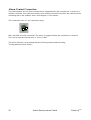
Alarm Contact Connection
The SolarLog800e has an alarm contact that is triggered when the connections is severed. A
weather-resistant, thin cable that breaks when stressed should be used for the cabling on the
mounting rod or the modules. Max. cable length is 1000 meters.
The connection uses a 3-pin connection plug.
1
3
PIN1 and PIN3 must be connected. The alarm is triggered when the connection is severed.
This can be reported via the relay, e-mail, or SMS.
The alarm function can be tested with the SolarLog display and the dialog
"Config/Advanced/Anti-Theft."
50
Solare Datensysteme GmbH
SolarLog800e
Connecting to the Computer/Network
The SolarLog800e is equipped with a standard Ethernet RJ45 network socket used to connect
with any commonly available network cable. The supported speeds are 10Mbit and 100Mbit.
Basically any type of computer network technology can be used to connect the SolarLog800e.
The following options are available:
1.
Direct cable connection
2.
Connection with network router
3.
Connection with power supply system (PowerLine)
4.
Connection with wireless network (WLAN / GSM)
Now connect the SolarLog800e using an Ethernet RJ45 network cable and the network adapter
in your computer, or use your network router, if available.
Please note that a so-called "crossover" network cable must be used for a direct SolarLog800e
to computer connection.
When using the SolarLog PowerLine kit, the SolarLog can be connected with the power plug
using the enclosed network cable. Then connect the computer / switch or Internet router with
the second power plug. The two power plugs automatically establish a connection with one
another and thereby serve as a "network cable via power supply" connection. The power plugs
should not be used in a multi-outlet power strip since other plugs may interfere with the data
quality.
The IP address of the SolarLog unit can be easily configured with the display. This process is
described in the user manual in chapter "Initial Startup."
SolarLog800e
Solare Datensysteme GmbH
51
Technical Data
Supply voltage
12 V DC
Energy consumption
Approx. 3.5 watt
Power Supply
External power adapter
Dimensions (W x H x D)
220 x 210 x 50 mm
Case
Plastic case
Passively vented
Interfaces
10/100Mbit Ethernet RJ45 socket
2xRS485, of these 1 RS422
Relay, 24VDC max. 5A max. time
S0 pulse input/output (acc. to DIN43864 and
62056)
Alarm contact, max. cable length 1000 m
USB host
Reset
Memory capacity
8 Mbyte RAM + min. 512 MB Flash RAM
Protection class
IP 20 (only for indoor use)
Temperature range
-10°C to 50℃
Indicator
4 LEDs for status indications
Installation
Wall mount
Internet Ports
The following ports must be opened on the router for the SolarLog if connected to the
Internet using a router:
Port 21
TCP
FTP data transfer (passive mode)
Port 53
UDP/TCP
DNS name resolution (separate DNS possible)
Port 123
UDP
NTP time server
Port 25
Port 80
52
TCP
TCP
SMTP sending email
HTTP web server
Solare Datensysteme GmbH
SolarLog800e
Timer
If a timer is used to sever the SolarLog from the mains power supply during the night, this can
be done in the time from 00:00 to 03:30. The SolarLog must be switched on at 4 am since
this is when the time is synchronized and the summertime/wintertime (daylight saving) switch
occurs.
SolarLog800e
Solare Datensysteme GmbH
53
CE Conformity Declaration
SolarLog800e
The manufacturer hereby declares that the described equipment conforms to the
European Directives, especially the EMC Directive acc. to 89/336/EEC and the Low
Voltage Directive 72/23/EEC.
The equipment corresponds with the following standards:
EMC Interference Radiation
:
Equipment Safety
EN 60950-1
EMC Interference Immunity
:
EN 61000-6-3
:
EN 61000-6-1
The equipment listed above is therefore labeled with the CE mark.
Rosenfeld, 24 October 2007
Solare Datensysteme GmbH
Jörg Karwath
Managing director
54
Thomas Preuhs
Managing director
Solare Datensysteme GmbH
SolarLog800e
Change History
Version
Date
Description
1.0.0
20.10.07
SolarLog800e
1.0.0-4
31.01.08
Changed contact assignment for connecting large display using S0
output
1.0.0-5
25.04.08
Description of the Powerlynx/Kyocera cable assignment was
flawed. Remedied.
Support for SMA-SB4000/5000TL-20-Next Generation.
Support for Sunways AT and Solarmax S-Series.
Support for Fronius IGPlus.
Added description for Solutronic, Schüco and REFUSOL.
Added Kaco8000xi description.
1.0.0-6
30.05.08
Added Kostal and Mastervolt.
1.0.0-7
01.07.08
Added Sunville / Phoenixtec.
Changed contact assignment again for connecting large display
using S0 output
SolarLog800e
Solare Datensysteme GmbH
55
56
Solare Datensysteme GmbH
SolarLog800e
SolarLog800e
Solare Datensysteme GmbH
57