1
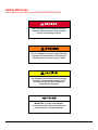
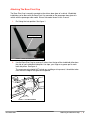
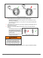
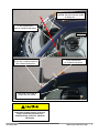
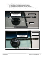
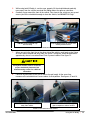
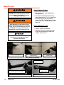
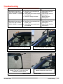
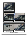
lil-BUDDY
TM
PRO1
Windshield Installation Tool
Operations Manual
MADE IN U.S.A.
lil-BUDDYTM
PRO1
Windshield Installation Tool
Contents
Safety Warnings . . . . . . . . . . . . . . . . . . . . . . . . . . . . . . . . . . . . . . . . . . . . . . . . . . . . . . . . . . . . . .2
Introduction . . . . . . . . . . . . . . . . . . . . . . . . . . . . . . . . . . . . . . . . . . . . . . . . . . . . . . . . . . . . . . . . . .3
Setting Up Lil Buddy . . . . . . . . . . . . . . . . . . . . . . . . . . . . . . . . . . . . . . . . . . . . . . . . . . . . . . . . . .4
Before You Start . . . . . . . . . . . . . . . . . . . . . . . . . . . . . . . . . . . . . . . . . . . . . . . . . . . . . . . . . .4
Health And Safety . . . . . . . . . . . . . . . . . . . . . . . . . . . . . . . . . . . . . . . . . . . . . . . . . . . . . . . . .4
Attaching The Base Pivot Cup . . . . . . . . . . . . . . . . . . . . . . . . . . . . . . . . . . . . . . . . . . . . . . .5
Attaching The Sliding Rod Cup . . . . . . . . . . . . . . . . . . . . . . . . . . . . . . . . . . . . . . . . . . . . . .8
Final Checks . . . . . . . . . . . . . . . . . . . . . . . . . . . . . . . . . . . . . . . . . . . . . . . . . . . . . . . . . . . .11
Using The Lil Buddy . . . . . . . . . . . . . . . . . . . . . . . . . . . . . . . . . . . . . . . . . . . . . . . . . . . . . . . . . .12
Maintenance . . . . . . . . . . . . . . . . . . . . . . . . . . . . . . . . . . . . . . . . . . . . . . . . . . . . . . . . . . . . . . . .16
Troubleshooting . . . . . . . . . . . . . . . . . . . . . . . . . . . . . . . . . . . . . . . . . . . . . . . . . . . . . . . . . . . . .17
Special Techniques . . . . . . . . . . . . . . . . . . . . . . . . . . . . . . . . . . . . . . . . . . . . . . . . . . . . . . . . . . .19
Working With Two-Framed Side Windows Or Obstructions . . . . . . . . . . . . . . . . . . . . . . . .19
Adjusting The Sliding Rod Cup Placement . . . . . . . . . . . . . . . . . . . . . . . . . . . . . . . . . . . . .20
December 2008
Contents
|
1
Safety Warnings
This is the highest level statement. Failure to
follow the listed instructions will most likely
result in severe injury or death.
This is a statement of serious hazard. Failure to
follow the listed instructions could place the
individual at risk of serious injury or death.
The statements used with this level of warning
deal with a safe operating procedure. If the
procedure is ignored, the possibility of
personal injury may exist.
IMPORTANT is used to draw attention
to a procedure that needs to be followed to
prevent machine or property damage.
2
|
Safety Warnings
December 2008
Introduction
Read and understand contents of this
manual and view the videotape that was
sent with the lil-BUDDY PRO1 prior to
using this tool.
The lil-BUDDY PRO1 windshield installation tool is intended to provide a safe and fast means
for installing windshields in most vehicles. The lil-BUDDY PRO1 when properly operated retains
a secure grip on one side of the windshield allowing windshield installation to be done by a
single technician. The technician can easily manoeuvre, and accurately position a replacement
windshield.
The lil-BUDDY PRO1 product is covered by following U.S. patents: (patent # pending) and
pending U.S. and foreign patent applications. lil-BUDDYTM, lil-BUDDYTM PRO and lil-BUDDYTM
PRO1 are a trademark of lil-BUDDY Corporation.
December 2008
Introduction
|
3
Setting Up The Lil Buddy
This section covers the setting up of the lil-BUDDY PRO1. It provides information about health
and safety, and checks that should be made prior to starting a job.
It assumes that you have already removed the old windshield, using any vehicle protection that
was necessary for that operation.
The actual windshield placement operation is covered under Using The Lil Buddy.
See page 12.
Before You Start
•
Use any additional tape or other protection on the paintwork around the edge of the
windshield opening.
•
Clean the glass on which the lil-BUDDY PRO1 is to be mounted to, ensure there is no
dust or dirt that will affect the strength of grip.
•
Completely close the window on which the Base Pivot Cup is to be mounted. If the window
is slightly open, there could be movement in the Base Pivot Cup that provides an unstable
lift for the technician.
•
•
Ensure that the door on which the Base Pivot Cup is to be mounted is completely closed.
•
•
Place the new windshield on a cradle to the side of the vehicle in readiness for placement.
Place some tape or retention strips on either side of the vehicle roof to use once the new
windshield has been fitted.
Locate two lil BUDDY Jr. suction cups to help with lifting the replacement windshield.
Health And Safety
Always follow the guidelines below when
using the lil-BUDDY PRO1.
4
|
•
To avoid the risk of harm to bystanders, make sure that people are kept away from the
working area while the glass replacement is in progress.
•
•
Wear safety gloves to protect the hands.
Wear safety glasses to protect the eyes.
Setting Up The lil BUDDY
December 2008
Attaching The Base Pivot Cup
The Base Pivot Cup is normally mounted on the drivers door glass of a vehicle. Windshield
installation can be done with the Base Pivot Cup mounted on the passenger door glass of a
vehicle with the passenger side model. Drivers side model shown in this manual.
1.
Pin Swing Arm into position. See figure 1.
Swing Arm pin
FIGURE 1 - SWING ARM PINNED INTO PLACE
2.
Use the Base Pivot Cup to measure 9 inches from the top of the windshield pillar down
the side of each windshield side pillar. Use tape, your finger or a grease pen to mark
both side pillars. See figure 2.
The measurements should NOT include any molding or trim present; it should be taken
from where the edge of the glass will be placed.
FIGURE 2 - 9 INCH MEASUREMENT
December 2008
Attaching The Base Pivot Cup
|
5
FIGURE 3 - BASE PIVOT CUP ANGLE
2.
Move the Base Pivot Cup and position it on the side window so that:
•
The Base Pivot Cup is parallel with the ground. Use the handle grip to visually
achieve this. See figure 3.
•
The red dot on the Swing Arm is in line with the 9” mark on both windshield side
pillars. See figure 5.
3.
Light pressure can be used on the cup to keep it in place on the door glass while it is
being positioned correctly.
4.
When you are completely happy with the position, firmly fix the cup by doing the
following:
•
Push the pump several times, rapidly.
As you do so the air between the cup
and the glass will be removed and
the amount of the button showing will
gradually reduce.
•
Keep pushing the pump until you can
no longer see the red line.
FIGURE 4 - PUMP CUP TO SECURE
After Base Pivot Cup has been secured to
the door glass, check placement to
ensure proper red dot location. If red dot
is not in-line with both windshield side
pillar markings, repeat steps 2 through 4.
5.
6 |
Pull the pin locking the Swing Arm into place so it is ready for windshield installation.
Attaching The Base Pivot Cup
Decemeber 2008
Eye sight line: Line up marks on both
windshield side pillars and the red dot
on Swing Arm.
9 inch measurement
mark on windshield side pillars.
Pump here
Red dot on swing arm must be
in-line with 9” measurements on
both windshield side pillars.
9 inch measurement
on windshield side pillars.
Base Pivot Cup should be
parallel with the ground.
FIGURE 5 - BASE PIVOT INSTALLATION
Swing Arm location must be correct for
proper windshield placement. See
troubleshooting section for additional
information.
December 2008
Attaching The Base Pivot Cup
|
7
Attaching The Sliding Rod Cup
Before installing the Sliding Rod Cup,
ensure that the outside of the windshield
is clean.
The Sliding Rod cup is placed on the new windshield before starting to lift it into position.
1.
Position a cradle close to the left-hand side of the vehicle and place the new windshield
on it, with the outer side facing upwards.
FIGURE 6 - WINDSHIELD POSITION
2.
On the right-hand side of the windshield, using the red line marked on the collapsed
Sliding Rod measure down 7 inches from the top. Mark with your finger or a grease
pen. See figure 7.
When taking this measurement:
•
The rod should NOT be extended.
•
The distance measured should NOT include any moulding or trim present; it should
be taken from where the glass starts.
7 inch measurement
FIGURE 7 - WINDSHIELD MEASUREMENT
8
|
Attaching The Sliding Rod Cup
December 2008
3.
Move the Sliding Rod Cup and position it on the glass so that:
•
The rod is parallel to the windshield top edge. See figure 8.
•
The center of the rod is centered on the 7 inch mark. See figure 8.
•
The Lil Buddy lable on the rod is just on the edge of the windshield. See figure 8.
7 inch measurement
to center of rod
lil-BUDDY Sticker
Pump here
Correct Position - PRO1 Model Shown
FIGURE 8 - SLIDING ROD CUP INSTALLATION
Red line on Sliding
Rod housing
14 inch measurement
to center of rod
Incorrect Position - PRO Model Shown
FIGURE 9 - SLIDING ROD CUP INCORRECT INSTALLATION
December 2008
Attaching The Sliding Rod Cup
|
9
4.
When you are completely happy with the position, firmly fix the cup by doing the
following:
•
Push the pump several times, rapidly.
As you do so the air between the cup
and the glass will be removed and
the amount of the button showing will
gradually reduce.
•
Keep pushing the pump until you can
no longer see the red line.
FIGURE 10 - PUMP CUP TO SECURE
After Sliding Rod Cup has been secured
to the windshield, check placement to
ensure proper rod location. If rod
movement occurred, repeat
steps 3 and 4.
5.
Attach two lil Buddy Jr. suction cups to the other side of the windshield. They can be
placed wherever you like, as long as they are shoulder width apart. So put them where
they feel most comfortable for you when lifting and moving the windshield. See figure
11.
lil BUDDY Jr. hand suction cups MUST BE
placed shoulder width apart for proper
windshield leverage.
6.
Use one of the lil Buddy jr. suction cups and the handle on the Sliding Rod Cup, to turn
the windshield over and round so that the Sliding Rod Cup is closest to the car.
FIGURE 11 - LIL BUDDY JR. PLACEMENT
10
|
Attaching The Sliding Rod Cup
December 2008
Final Checks
With both Lil Buddy components in place, take some time to visually check everything is
correct. This is the time to make any final adjustments and corrections to ensure a
straight-forward replacement.
•
Make sure the two units are positioned correctly on the glass.
•
Ensure the red line on the pump of each unit is not showing. If it is, the cup is not
totally secure on the glass. To rectify it, push the pump a few times, rapidly, unit the red
line is no longer in view.
Visually check cup seals before setting
windshield into place. A red line showing
on the cups brass pump rod indicates a
bad seal. DO NOT use the Lil-Buddy with
a bad seal.
•
December 2008
Ensure you have placed some tape or retention strips either side of the vehicle roof.
These will be used to prevent slippage once the new windshield has been fitted.
Final Checks
|
11
Using The Lil Buddy
Visually check cup seals before setting
windshield into place. A red line showing
on the cups brass pump rod indicates a
bad seal. DO NOT use the Lil-Buddy with
a bad seal.
NOTE: It is advisable to do a test-run of putting the new windshield in place prior to gluing. This
is so you can work out the exact manoevring required without having to worry about
accidentally smudging glue on the paintwork.
1.
Turn the windshield over on the cradle and prep for windshield for installation, apply
glue.
2.
If necessary, move the cradle with the windshield close to the side of the vehicle where
the Base Pivot Cup is attached to the door glass.
3.
Adjust the end of the rod so it is the correct way for placing onto the Base Pivot Cup.
The side with the deeper cut-out needs to be facing upwards; the side of the shallower
cut-out need to be facing downwards. There should be a sticker on the rod end showing
which side is up. See figure 12.
FIGURE 12 - SLIDING ROD END
4.
Fully extend the sliding rod and carefully place the rod end onto the pin at the end of
the Swing Arm. See figure 13.
FIGURE 13 - INSTALLATION OF SLIDING ROD END TO SWING ARM
12 |
Using The Lil Buddy
December 2008
5.
While using both lil Buddy Jr. suction cups, properly lift the windshield and gradually
move away from the vehicle to extend the sliding rod out for optimum clearance.
6.
Gradually move around the front of the vehicle. Stay close to the vehicle as you go and
ensure you lift the windshield enough to clear the vehicle, but DO NOT lift it high.
DO NOT hold windshield high
over the body.
Keep windshield close to vehicle while
walking around vehicle.
FIGURE 14 - WALK WINDSHIELD INTO POSITION
7.
When you get to the front tire on the other side of the vehicle, push back on the Swing
Arm so it moves around and away from the vehicle. Swing Arm should be positioned
approximatly where it was when Base Pivot Cup was installed. See figure 15.
Swing Arm location must be correct for
proper windshield placement. See
troubleshooting section for additional
information.
8.
Continue to push back on the arm to reduce the rod length. At the same time,
manoeuvre the windshield so it hovers above its final position. See figures 15 and 16.
Push back on Swing Arm to move it
away from vehicle.
DO NOT allow windshield to drag the
glue on top drivers side of vehicle.
FIGURE 15 - WALK WINDSHIELD INTO POSITION
December 2008
Using The Lil Buddy
|
13
Push upper cup away from you
to collapse Sliding Rod.
Hold lower cup in position or
slightly pull toward you.
FIGURE 16 - COLLAPSE SLIDING ROD
9.
Use the following sequence to drop the windshield into its final position.
•
Set the top corner of the windshield into place.
•
Move the windshield, as necessary, to position it correctly over the bottom corner.
•
Set the bottom corner into place.
2 inches
DO NOT set bottom of windshield first.
Set top of windshield first. Should have
approximately 2 inches of equal clearance.
FIGURE 17 - WALK WINDSHIELD INTO POSITION
10. Place the retention strip or tape from the vehicle roof across the top of the vehicle and
windshield to prevent it slipping while the glue is bonding.
11. Walk around to the other side of the vehicle.
14 |
Using The Lil Buddy
December 2008
DO NOT touch extended (silver) portion
on the Sliding Rod. ALWAYS hold black
Sliding Rod Housing.
12. Take hold of the black Sliding Rod Housing and support the weight of the windshield.
Release the Swing Arm pin and pivot arm out of the way. See figure 18.
Turn clockwise on Swing Arm pin and
then pull down to release.
Once Swing Arm pin is released pivot Swing
Arm out of the way.
FIGURE 18 - SWING ARM PIN RELEASE
13. As you drop the Sliding Rod Housing, fit the windshield into its final postion by lining-up
the top corner and then placing the whole side into position in one operation.
14. Place the second retention strip or tape across the top of the vehicle and windshield.
15. Remove the Base Pivot Cup and Sliding
Rod Cup from the glass by pressing the
release levers. You could also use your
finger to break the seal between the cup
and glass. See figure 19.
16. Put the units immediately into the carry
case.
FIGURE 19 - RELEASE CUPS
December 2008
Using The Lil Buddy
|
15
Maintenace
Every 50 Sets or 30 Days
DO NOT touch extended (silver) portion
on the Sliding Rod. ALWAYS hold black
Sliding Rod Housing.
After lubication; slowly collapse silver
Sliding Rod allowing excess oil to escape
out the end of black Sliding Rod Housing.
BEWARE oil will spray out the black
Sliding Rod Housing if collapsed to fast.
1. Extend and clean sliver Sliding Rod.
See figure 20.
2. Lubricate black Sliding Rod Housing.
Spray approximately 2 to 3 seconds into
housing to ensure full lubrication of
seals. Use CRC TrueTap Foamy Cutting
Fluid or specific lil Buddy lubricate. See
figure 20.
Every 1000 Sets or 1 Year
1. Preform 30 days maintenace.
2. Lubricate Swing Arm needle bearings.
Check for worn bearings, replace as
needed. See figure 21.
Be sure to clean up excess oil after
lubricating Sliding Rod.
Lubricate inside wall of
black housing
Clean silver Sliding Rod
Lubricate plastic
housing end
FIGURE 20 - SLIDING ROD LUBRICATION
Wear Item Replace if worn
Needle bearing one per side
Use Blue Loctite on threads when
re-installing Swing Arm bolt.
Remove Swing Arm using 13/16 inch wrench
Check and lubricate needle bearings
FIGURE 21 - SWING ARM NEEDLE BEARINGS
16 |
Maintenance
December 2008
Troubleshooting
Problem
Probable Cause
Solution
1. Windshield is hovering to
a. Base Pivot Cup mounted to low. a. Adjust Base Pivot Cup
close (low) to side of vehicle
on door glass.
See figure 22.
where lil BUDDY is mounted. b. Sliding Rod Cup mounted to high b. Adjust Sliding Rod Cup
on windshield.
See figure 23.
c. Swing Arm swung to far back
c. Adjust Swing Arm
See figure 24.
2. Windshield is hovering to far a. Base Pivot Cup mounted to high
(high) from side of vehicle
on door glass.
where lil BUDDY is mounted. b. Sliding Rod Cup mounted to low
on windshield.
Base Pivot Cup mounted to low.
Notice: Red Dot on Swing Arm below pillar.
a. Adjust Base Pivot Cup
See figure 25.
b. Adjust Sliding Rod Cup
See figure 26.
Result: Windshield to close to glue.
FIGURE 22 - BASE PIVOT CUP MOUNTED TO LOW
Sliding Rod Cup mounted to high.
Notice: Less then 7 inches from top of
windshild to centerline of rod.
Result: Windshield to close to glue.
FIGURE 23 - SLIDING ROD CUP MOUNTED TO HIGH
December 2008
Troubleshooting
|
17
Notice: Swing Arm swung to far to rear of vehicle.
Result: Windshield to close to glue.
FIGURE 24 - IN-CORRECT SWING ARM POSITION
Base Pivot Cup mounted to high.
Notice: Red Dot on Swing Arm above pillar.
Result: Windshield to high from glue.
FIGURE 25 - BASE PIVOT CUP MOUNTED TO HIGH
Sliding Rod Cup mounted to low.
Notice: More then 7 inches from top of
windshild to centerline of rod.
Result: Windshield to high from glue.
FIGURE 26 - SLIDING ROD CUP MOUNTED TO LOW
18 |
Troubleshooting
December 2008
Special Techniques
Working With Two-Framed Side Windows Or Obstructions
As you become more experienced at using the Lil Buddy you may have to vary the position of
the Base Pivot Cup on the side door glass to avoid potential obstructions to the working of the
units.
In these cases, the Sliding Rod Cup placement also has to be adjusted accordingly.
1.
Attach the Base Pivot Cup (see page 5) in the standard way; except with the Swing
Arm pinned into its fully extended position, placing the red dot anywhere along the
windshield pillar as required. See figures 27 and 28.
Example: Red dot
positioned 16 inches
down windshield pillar.
Line up red dot on Swing Arm
anywhere along windshield
pillar when mounting Base
Pivot Cup.
FIGURE 27 - SWING ARM PINNED FULLY EXTENDED
2.
FIGURE 28 - ALTERNATE BASE PIVOT CUP MOUNT
Measure the distance from the top of the windshield pillar down the side pillar to the red
dot mark. Be sure your sight line is in line with both side pillars and the red dot when
taking this measurement. Example 16 inches, See figure 28.
This is used for the placement of the Sliding Rod Cup on the new windshield.
3.
Follow the standard procedure (see page 8) for positioning the Sliding Rod Cup on the
new windshield, except:
•
Instead of measuring 7 inches from the top, measure the amount you have just
noted, less 2 inches. Example 14 inches, See figure 29.
•
Use the red line on Sliding Rod when placing Sliding Rod Cup. See figure 9.
Tip: The easiest way of completing the last two steps is to use the Sliding Rod Cup to
measure the distance down the side pillar on the vehicle - essentially, place the rod at
the top of the pillar to red dot mark on the side pillar. Then when you place the Sliding
Rod Cup on the new windshield, use the rod length, less 2 inches, for the required
measurement. See figure 29.
Mark for Sliding Rod placement
less 2 inches
14 inches
Use red line when placing Sliding
Rod Cup onto windshield
FIGURE 29 - USING SLIDING ROD TO OBTAIN MEASUREMENT
December 2008
Special Techniques
|
19
Adjusting The Sliding Rod Cup Placement
The standard placement for the Sliding Rod Cup on the new windshield, as described in the
manual, will give a gap of about 2 inches between the new glass and the aperture, when fitting.
This will be fine for 90% of replacements.
2 inches
FIGURE 30 - STANDARD WINDSHIELD GAP
However, it is possible to adjust the Sliding Rod Cup placement, altering the 2 inch gap width,
to cope with different circumstances that you might encounter. For example:
•
Obstruction of hood or fender - the gap between the new windshield and pillar should
be reduced to enable the glass to be positioned under the obstruction easily.
•
Heavy windshields - the Sliding Rod Cup should be placed lower to give a more even
spread of weight for the technician.
As you become more experienced at using the Lil Buddy you will be able to view the car and
windshield type, and make an assessment on the Sliding Rod Cup placement.
1.
Attach the Base Pivot Cup (see page 5) in the standard way.
2.
Follow the standard procedure (see page 8) for positioning the Sliding Rod Cup on the
new windshield, that is:
•
The rod is parallel to the windshield top edge.
•
The center of the rod is above or below the 7 inch mark.
•
The Lil Buddy lable on the rod to the side edge of the windshield.
Tip: For every 1 inch you move the Sliding Rod from the standard 7 inch placement; the
windshield gap will either increase or decrease approximately 1/2 inch.
See steps 3 and 4.
20 |
Special Techniques
December 2008
3.
To reduce the gap between the windshield and the pillar, the Sliding Rod Cup needs to
be placed higher up the windshield. See figure 31.
2 inches
FIGURE 31 - DECREASE WINDSHIELD GAP
4.
To widen the gap between the windshield and the pillar, the Sliding Rod Cup needs to
be placed lower down the windshield. See figure 32.
2 inches
FIGURE 32 - INCREASE WINDSHIELD GAP
When widening the gap, you have to be aware that it pulls the windshield across
towards the Base Pivot Cup, which could potentially alter the placement you have
already done on the other side of the vehicle. Essentially, the higher the windshield, the
greater the likelihood of it being pulled out of position on the other side.
December 2008
Special Techniques
|
21
STANDARD WARRANTY
Lil BUDDYTM warrants that its products will be free from defects in design, materials, and workmanship for a
period of 365 days from the date of shipment. All claims for breach of this warranty must be made within 30 days
after the defect is or can, with reasonable care, be detected and in no event no more than 30 days after the warranty has expired. In order to be entitled to the benefits of this warranty, the products must have been properly
installed, maintained, and operated within their rated capacities and/or specified design parameters, and not
otherwise abused. This warranty is Lil Buddy’s exclusive warranty. LIL BUDDY EXPRESSLY DISCLAIMS ALL
IMPLIED WARRANTIES, INCLUDING THE IMPLIED WARRANTIES OF MERCHANTABILITY AND FITNESS.
Non-standard warranties, if any, must be specified by Lil Buddy in writing.
In the event of any defects covered by this warranty, Lil Buddy will remedy such defects by repairing or replacing
any defective equipment or parts, bearing all the costs for parts, and transportation. This shall be the exclusive
remedy for all claims whether based on contract, negligence, or strict liability.
LIMITATION OF LIABILITY
LIL BUDDY SHALL NOT IN ANY EVENT BE LIABLE FOR ANY LOSS OF USE OF ANY EQUIPMENT OR
INCIDENTAL OR CONSEQUENTIAL DAMAGES OF ANY KIND, WHETHER FOR BREACH OF WARRANTY,
NEGLIGENCE, OR STRICT LIABILITY.
Australian Distributor:
BTB Tools
1b Wood St
Bendigo VIC 3550
t. 03 5443 1755
f. 03 5441 5263
e. [email protected]
w. www.btbtools.com