1
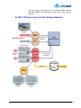
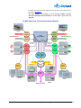
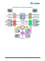
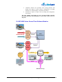
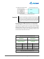
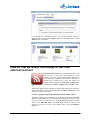
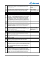
Automation System GPI Relay Output
or SL NEO Server GPI Relay Output
SL NEO Server GPI IN
or Automation System GPI IN
GPI IN
Ground
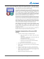
General Flow Chart for Connecting the GPI Interfaces
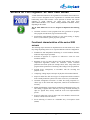
Important
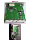
The presence of GPI interfaces is an option for SL NEO servers and
processors. If the GPI option was ordered, see the accompanying
card to the server, on which the number and location of the sockets
for the control interfaces are indicated, the types of control signals
are marked, and a pin definition of the multi-contact GPI sockets is
given.
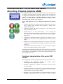
Connecting the VTR to the Server’s Serial Port
An SL NEO server can control several (up to 8) tape recorders through RS232/422 interfaces through the SONY 9 Pin Remote Protocol or through
IEEE1394 (FireWire) interfaces. If the VTR control option was ordered and the
corresponding software settings have been made, you must prepare a tape
recorder control cable in accordance with the established types of RS-232 or RS422 control interface and the tables shown below.
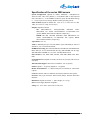
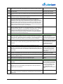
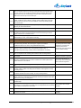
VTR control cable: RS-422Moxa/RS-422VTR
DB9 MALE
DB9 FEMALE
SONY RS-422 9-pin VTR
Remote Connector
SL NEO SERVER RS-422
Moxa Port
1
2
3
7
GND
Tx-(A)
Rx+(B)
Tx+(B)
5
4
2
3
GND
Rx-(A)
Tx+(B)
Rx+(B)
8
Rx-(A)
1
Tx-(A)
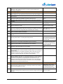
VTR control cable: RS-232/RS-422VTR
The SL NEO Media Server. User Manual. © 2009-2011 Skylark Technology, Inc.
51