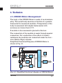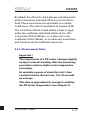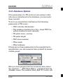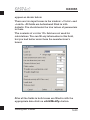
1
RMT Ltd Joint Stock Company Z-Meter (TE Module Parameters Meter) DX3065 Series User Guide 2002 Rev. 1.00 DX3065 RMT Ltd Edition July 2002 Copyright All right reserved. Reproduction in any manner, in whole or in part is straightly prohibited without written permission of RMT Ltd. The information contained in this document is the subject to change without notice. Limited Warranty RMT Ltd warrants that DX3065 Meter, if properly used and installed, will be free from defects in material and workmanship and will substantially conform to RMT’s publicly available specification for a period of one (1) year after date of DX3065 Meter was purchased. If the DX3065 Meter which is the subject of this Limited Warranty fails during the warranty period for the reasons covered by this Limited Warranty, RMT, at this option, will : REPAIR the DX3065 Meter; OR REPLACE the DX3065 Meter with another DX3065 Meter. Trademark Acknowledgments All trademarks are the property of their respective owners. RMT Ltd. 53 Leninskij prosp. Moscow 119991 Russia phone: 095-132-6817 fax: 095-132-5870 e-mail: [email protected] http://www.rmtltd.ru REV. 1.00/2002 RMT Ltd DX3065 Contents 1. Introduction 2. Principle of Time Constant Measuring 2.1. Theoretical Grounding 2.2. Interpolation Results 2.3. Theory of Operation: 3. Principle of Figure-of-Merit Measuring 3.1. Theory of Operation: Single-stage TEC 3.2. Figure-of-Merit and DTmax for Single-stage 1-1 2-1 2-1 2-3 2-9 3-1 3-1 3-7 TEC 3.3. Theory of Operation: TEC mounted on the heat sink 3.4. Theory of Operation: Z-measuring of Twostage TEC 3.5. Material Z and Measured Z 4. Technics 4.1. DX3065 Meter Arrangement 4.2. AC Resistance Measurement 4.3. U and Ua Measurement 3-13 4-1 4-1 4-2 4-4 5. Working with Z-Meter 5.1. System Requirements 5.2. Program Installation 5.3. Hardware Preparation 5.4. Measurement of Parameters of TE coolers 5.5. The Main Program Window 5.5.1. Title 5.5.2. Menu bar 5.5.3. Reference Bar 5.5.4. Functional Fields 5-1 5-1 5-1 5-3 5-5 5-8 5-8 5-8 5-10 5-11 Contents 3-8 3-10 DX3065 RMT Ltd …Contents 5.6. Single-stage TEC Z-metering 5.6.1. Reference 5.6.2. Cooler type 5.6.3. Corrections Field 5.6.4. Measurement Notes 5.7. Z-metering of a Single-stage TEC on Heat Sink 5.8. Z-metering of Two-stage TEC 5.9. History 5.10. Database Update 6. Maintenance 7. Standard Kit 8. Specifications 5-14 5-14 5-15 5-16 5-17 5-19 5-19 5-20 5-22 6-1 7-1 8-1 REV. 1.00/2002 RMT Ltd DX3065 1. Introduction The DX3065 Z-Meter provides precise measurement of Thermoelectric modules’ parameters. AC resistance (R) Figure-of-Merit (Z) maximum temperature difference (DTmax) time constant Using DX3065 Z-Meter it is possible to perform testing of various types of single- and two-stage TE modules. Additionally, it is possible to evaluate quality of threeor more-stage TE modules by the measurement of electrical resistance. Although the above listed parameters are measured at ambient temperature DX3065 Z-Meter provides recalculation of them to any standard temperature (+20°C or another software selectable). The DX3065 Meter is managed by any IBM compatible computer under Windows95/98/2000 operating system. Introduction 1-1 DX3065 1-2 RMT Ltd REV. 1.00/2002 DX3065 RMT Ltd 2. Principles of Time Constant Measuring 2.1. Theoretical Grounding Let us consider a one-stage thermoelectric cooler (TEC). The ambient temperature is Ta. At a certain moment the electric current in the TEC is turned on. The differential equation result for the TEC transient dynamics can be presented as the following exponential superposition: ¥ DT(t, x) = å (AnUn (x))e -mnt + DTst (x) (2.1) i =1 where DT(t,x)=T-Ta, T is the temperature of the TEC point located at a time t and a generalized coordinate x, Un and mn are the eigenfunctions and eigenvalues, An are the thermal amplitudes, DTst(x) is the stationary result value. The solution (2.1) analysis yields that the cooling process can be divided into two stages: irregular and regular. The first one is dictated by the initial moment's Principles of time constant Measuring 2-1 DX3065 RMT Ltd conditions and is described by a multi-exponential interference. This stage fades out rather quickly and in case TEC pellets thermal conductance is high enough, the temporal behavior can be characterized by the only exponent, i.e: m min << m n (2.2) for all possible indices n. The theory yields the following expression for the time constant t = 1/mmin of single-stage TEC's: t= LC Laj ö æ ç1 + ÷ skN k ø è (2.3) where C a k N L s j 2-2 - TEC cold side heat capacity, - the thermoelectric (TE) material Seebeck constant, - the TE material thermal conductivity, - the TEC pellets number, - the pellets length, - their cross-section, - the electric current density. REV. 1.00/2002 DX3065 RMT Ltd As (2.3) shows, t calculation is stumbling because in practice the values involved in it are never known to the proper accuracy extent. The DX3065 allows to measure the time constant of single-stage TEC's and to estimate that of more-stage ones. 2.2. Interpolation Results The procedure of handling the time constant measurement data is as follows. The temporal behavior of a single-stage TEC temperature difference is measured via the Seebeck voltage that is a corresponding proportional value: Ua = aDT (2.4) For a two- or more-stage TEC this simple ratio is not applicable. However the time constant can be estimated by the temporal dependence of the Seebeck voltage and the approach for obtaining the stationary voltage values is the same. The measuring procedure is carried out both for two electric supply polarities. The data collection duration and time step can be varied. The measuring chart window is presented in Fig. 2.1. Principles of time constant Measuring 2-3 DX3065 RMT Ltd Fig. 2.1. Measuring window of Z-Meter program The obtained experimental data is then fitted by the following function: U a (t) = Usta (1 - e - t/t ) (2.5) The exponential regression is based on the method of least squares. As its outcome the procedure provides the time constant t and the stationary Seebeck voltage Usta. 2-4 REV. 1.00/2002 DX3065 RMT Ltd 3. Principle of Figure-of-Merit Measuring 3.1. Theory of Operation: Single-stage TEC Among three parameters (R, Z, DTmax) measured by DX3065 Meter only AC resistance R is measured directly. The R measurement method is described in the Part “AC Resistance Measurement” of Chapter 4. The determination of the Figure-of-Merit Z and the maximum temperature difference DTmax of a thermolelctric (TE) module implements an indirect method, which allows to avoid labour-consuming thermophysical measurements. This approach is based on the Harman method. The Figure-of-Merit is the most important performance parameter of a TE cooler. It is defined as Z= a2 kR (3.1) where a k R - TE material Seebeck coefficient, - thermal conductance of TE pellets material, - Ohmic resistance of TE module. Principle of Figure-of-Merit Measuring 3-1 DX3065 RMT Ltd From this time on we deal with the stationary mode values only (see Ch.2). T0 T1 The base equations that describe a one-stage TE module power balance a0 a1 1 2 ì a0 (T a - T 0 ) ïïaIT 0 - 2 I R - k' DT = N í ïaIT + 1 I 2R - k' DT = a1 (T 1 - T a) 1 ïî N 2 (3.2) where 3-2 T0 - cold surface temperature, T1 - hot surface temperature, DT = T1 - T0, Ta - ambient temperature, I N a0 a1 - current passing through TE module, - TE pellets number, - environment-cold side heat transfer term, - environment-hot side heat transfer term, k¢ - effective pellets thermal conductance. REV. 1.00/2002 DX3065 RMT Ltd The term k¢ describes thermal conductance normalized to one pellet between the cold and hot surfaces: k' = k(1 + b th ) (3.3) bth = Bcond + Brad (3.4) where The Bcond and Brad are corrections for inter-pellets thermal conductance values through air thermal conductivity and radiation, respectively: Bcond = ö k air æ 1 ç - 1÷ k èb ø (3.4a) Here the pellets filling term is: b= Ns S where s - a pellet cross section, S - the cold side area. Brad = g S s T 3a (1 - b ) Nk (3.4b) where s g - Boltzman constant, - thermal emissivity. Principle of Figure-of-Merit Measuring 3-3 DX3065 RMT Ltd At the heat exchange with environment ai << k' N and the current I << k' a (3.5) (3.6) we have 2 æ Ua RN ö÷ ( a 0 - a 1 ) Ia (3.7) = Z' ç Ta + I + ç a 0 + a 1 ÷ 2 k' ( a 0 + a 1 ) UR è ø where Ua = a( T1 - T0 ) - thermoelectric component of the voltage dropout on a TE module (the Seebeck voltage), UR = IR - Ohmic component of the voltage dropout on a TE module. 2 Z' = a k' R Equation (3.7) contains directly the ambient temperature. If using the average temperature we should have allowed for the additional term ~ a/2Nk characterizing heat dissipation from the external surfaces. Formula (3.7) takes this term into account automatically via the ambient temperature value. 3-4 REV. 1.00/2002 DX3065 RMT Ltd Consider the equation for Z (3.7). The second term in (3.7) generates a certain correction. It is remarkable however that this term is a linear function of the current. As a consequence summing the æ æ Ua ö æ Ua ö I 2 RN ö ÷ çç ÷÷ + çç ÷÷ = 2 Z ¢ çç Ta + a1 + a2 ÷ø è U R ø+ è U R øè (3.8) That is we managed to solve the problem avoiding any asymmetry correction challenge. So, the value Z (= a2/kR) could be obtained as ìïé ù üï 1 U a Z= 1 + bth (1 + br )ý íê ú Ta ( 1 + bT ) ïëêUR ûú averaged ïþ î ( ) (3.9) where 1 I 2RN bT = Ta a0 + a1 (3.9a) Correction factor to ambient temperature due to Joule heating Principle of Figure-of-Merit Measuring 3-5 DX3065 RMT Ltd bth = Bcond + Brad (3.9b) br = r (3.9c) RTEC Correction factor to pellet thermoconductivity due to additional heat flux from the warm side to the cold one through the medium (according to (3.2)) Correction factor because of a non-zero resistance of TE module wires where RTEC = NR (The total voltage drop UR is a sum of the drop UTEC at the module and some additional drop at terminal wires (r is their resistance), so U'R = I (RTEC + r )= I RTEC (1 + br ) UR = U'R (1 + br ) (3.10) (3.11) Due to the above formulated correction factors eliminate the effect of actual arrangement of Zmetering technique on the Z-value and allows to estimate the true material Figure-of-Merit. 3-6 REV. 1.00/2002 DX3065 RMT Ltd 3.2. Figure-of-Merit and DTmax for Singlestage TEC The Z value corresponds to the maximum temperature difference on a module DTmax by a simple ratio D T max = 1 2 Z T0 2 (3.12) However the direct measurement of T0 is complicated. A more convenient way is to measure the temperature difference through the hot surface temperature T1 : T0 = T 1 - DT max If the heat sink thermal resistance is little, the hot side temperature approaches the ambient temperature and T1 » Ta is used instead of T1. Hence there is the following equation for DTmax : DT max = 1 Z (Ta - DT max )2 2 (3.13) Then it is easy to recalculate the value DTmax as a function of the ambient temperature: D T max (T a) = T a - Principle of Figure-of-Merit Measuring 1 + 2Z T a - 1 Z (3.14) 3-7 DX3065 RMT Ltd Here the dependence of Z on the temperature was ignored, which is quite allowable at the temperature scale considered. For instance if Z=0.0027 K-1, and Ta =300K we have the following temperature difference DTmax ~ 70 K. 3.3. Theory of Operation: a TEC mounted on the heat sink a0 L Heat sink means a noticeable increase of heat dissipation through the TEC basement. It must be a1 taken into account when estimating the role of this factor in measurement results. Equation (3.9) üï ìïé ù 1 U a Z= 1 + bth (1 + br )ý íê ú + ( 1 ) U Ta bT ïêë R úû averaged ïþ î ( 3-8 ) REV. 1.00/2002 DX3065 RMT Ltd allows for heat dissipation through the warm side of TE with the corresponding term bT and the voltage averaging. So the estimation of the bT value of the assembled TE module is possible if taking into account thermal properties of the heat sink. As a rough estimation we can assume a1 = kS SS LS (3.15) where kS - thermal conductivity of the heat sink, SS - surface of the heat sink as the TEC projecting; - thickness of the heat sink. LS Principle of Figure-of-Merit Measuring 3-9 DX3065 RMT Ltd 3.4. Theory of Operation: Z-measuring of a Two-stage TEC a0 T0 T1 T2 N2 N1 a2 1 2 ì ïï aIT0 - 2 I R - k' (T1 - T0 ) = í 1 ïaIT2 + I 2 R - k' (T2 - T1 ) = 2 îï where Hereinafter we deal with the stationary mode values only (see Ch.2). The general formulae for a two-stage module cold and hot sides are: a0 (Ta - T0 ) N1 (3.16) a2 (T2 - Ta ) N2 T0, T1, T2 - TE module's cold side, medium and hot side temperatures, respectively. N1, N2 - pellet numbers at the first and second stages. If it is possible to assume that the heat transfer coefficient ai and the pellets number Ni are proportional to the corresponding cold side areas Si a0 a = 2 = A = const , N1 N 2 3-10 (3.17) REV. 1.00/2002 DX3065 RMT Ltd and bi = Nis = const , Si (3.18) equations (3.16) are modified the following way: 1 2 ì a IT I R - k' (T1 - T0 ) = A(Ta - T0 ) 0 ï 2 (3.19) í 1 ïaIT2 + I 2 R - k' (T2 - T1 ) = A(T2 - Ta ) î 2 Summing up equations (3.19) we derive: 2aIT = ( k' + A)DT where T = (3.20) T2 + T0 is the average module temperature. 2 Solving the following set of equations ì ï ï2aIT = ( k' + A) DT ï 1 æ U R1 U R2 ö ï ÷ ç + íI = 2 R çè N1 N 2 ÷ø ï ï U U ïDT = 1 æç a1 + a 2 ö÷ ï a çè N1 N 2 ÷ø î Principle of Figure-of-Merit Measuring (3.21) 3-11 DX3065 RMT Ltd we obtain the following Z T = ( 1 + b th )( 1 + b r ) Ua UR bth = Bcond + Aconv + ( Brad + Arad ) (3.22) (3.23) The parameters Bcond, Brad are described above (3.4a, 3.4b). al (3.24) Aconv = kb A rad = g sTa3l kb (3.25) where Aconv, Arad stand for convection and radiation external heat transfers, respectively. The problem stated by eq. (3.16) is polaritysymmetrical. So, the averaging of the different polarity voltage ratios for accuracy concerns is appropriate. So eq. (3.22) can be rewritten as: éU ù Z T = ( 1 + bth )( 1 + br )ê a ú (3.26) ë U R û averaged Knowing the Z-value we can evaluate DTmax = T1 - T0 finding the maximum of the following function: 3-12 REV. 1.00/2002 DX3065 RMT Ltd DT ( x ) = Ta - x2 1 2 Z (x + 1) ((x - 1)x + x + 1)(x + 1)- 1 é ù x2 x2 ´ ê(x + 1) + xTa + 2Z 2 Z (x + 1)úû ë (3.27) where x = N2 N1 x= aI k' - the cascading coefficient, - dimensionless current. For instance if Z=0.0027 K-1, and Ta =300K we have the following temperature difference DTmax ~ 100 K. 3.5. Material Z and measured Z Regarding all the correction factors discussed above, it is clear that the material Figure-of-Merit (when there is no heat exchange with environment) is always higher than the measured Figure-of-Merit. It is convenient to relate the two values via the coefficient a >1: Z = a Zmeasured Principle of Figure-of-Merit Measuring (3.28) 3-13 DX3065 3-14 RMT Ltd REV. 1.00/2002 DX3065 RMT Ltd 4. Technics 4.1. DX3065 Meter Arrangement The body of the DX3065 Meter is made of an aluminum alloy. The metal body executes a function of a passive thermostat for measured modules. Temperature of the body is measured with digital thermometer with accuracy not worse than 0.1°Ñ. A module to be measured is placed in this box. The connection of the module is made through special connectors. For a reduction of the effect of contact resistance the modules are connected under the fourwire (Kelvin Clips) scheme. Simplified Functional Diagram of DX3065 Meter is shown in Fig. 4.1. +5V TEC Temp. Sensor + Instrumentation amplifier ADC SPI +4.096 V precision reference Pprecision current source Microcontroller EEPROM I 2C RS-232 driver RS-232 DAC Fig. 4.1. Simplified functional diagram of DX3065 Meter Technics 4-1 DX3065 RMT Ltd 4.2. AC Resistance Measurement TEC For resistance measuring the module is tested by AC of a small amplitude. The AC is simulated with the Commutator, which periodically (with 50% duty circle) reverses a circuit of Im Em Current the reference current source Im. The simplified diagram of the Commutator is shown Instrumentation in Fig. 4.2. Amplifier In the no input signal Fig. 4.2. The simplified state the output diagram of AC resistance voltage of the measuring Instrumentation Amplifier (IA) is equal to Em/2, where Em = 4.096 V (Fig. 4.3). T T +Em /2 0 t1 t2 t3 t4 Up1 Un1 Up2 Un2 t2 n-2 t2 n-1 t2 n Unn-1 Upn Unn Fig. 4.3. Output signals of Instrumentation Amplifier at AC resistance measuring 4-2 REV. 1.00/2002 DX3065 RMT Ltd During AC resistance measuring the output voltage of the IA is sampled and measured by 12 bit ADC every time before Im current reversing. The sampling points are marked as ti in Fig. 4.3. The voltage drops on TE module when positive current (Upi) and negative current (Uni) are used for a TE module resistance (R) calculation under the following formula : n R= where å (Upi - Uni) i =1 2 × I m × AV × n (4.1) Upi - voltage drop on TE cooler at positive testing current Im Uni - voltage drop on TE cooler at negative testing current Im Im - testing current AV - voltage gain of Instrumentation Amplifier n - total number of samples per measurement The typical values of parameters in formula (4.1) are as follows: Im = 2 mA AV = 5 or 50 n = 50 Technics 4-3 DX3065 RMT Ltd 4.3. U and Ua Measurement At measurement of U and Ua parameters the small current IT is applied to a module periodically (with 50% duty circle). Two successive measuring sessions are necessary to obtain the U and Ua values at different testing current polarities. Testing current IT 0 TEC total and Seebeck voltages Uai Ui Uai+1 Ui+1 Uan+1 Un+1 0 Fig. 4.3. Test current and voltages schematic temporal behaviour 4-4 REV. 1.00/2002 RMT Ltd DX3065 5. Working with Z-Meter The DX3065 Meter works under the control of the ZMeter program. The Z-Meter program provides all possible operational modes of the DX3065 Meter. The Z-Meter has the simple interface and does not demand a User's special knowledge. The Z-Meter software is delivered with the DX3065 Meter. 5.1. System Requirements IBM PC compatible computer with Windows 95/98/2000 operating system Free COM port 2 MB free hard drive space (additional space may be required later as your database grows) Mouse or compatible pointing device 5.2. Program Installation Z-Meter is supplied on CD. Insert the CD into the appropriate drive and start the Setup program. The window of the standard Windows installer will appear (Fig. 5.1). Working with Z-Meter 5-1 DX3065 RMT Ltd Pass all the steps of the installation procedure sequentially according to the installer directions. When selecting the logic disk you must keep in mind that the program requires not less than 2 Ìb of hard disk space. (As database size increases the additional disk space can be required). Fig. 5.1. The Z-Meter installation window 5-2 REV. 1.00/2002 DX3065 RMT Ltd 5.3. Hardware Preparation Turn DX3065 Meter back side to yourself. From this side you will find out the following elements (Fig. 5.2): Power ON/OFF button LED power indicator Power supply input connector RS-232 connector LED power Indicator Power ON/OFF Button Power Supply Input RS 232 RS-232 Port Fig. 5.2. The back side of DX3065 meter Working with Z-Meter 5-3 DX3065 RMT Ltd 1. Make sure, that the DX3065 is switched off. Fig. 5.3. RS-232 interface cable connection 2. Using the DX3065-C01 cable connect DX3065 Meter to COM port which you are going to use for DX3065 driving (Fig. 5.3). 3. Connect the AC/DC adaptor to Power Supply Input (Fig 3.4). 4. Push «Power ON/OFF» button and turn the Meter on. 5. Turn on your computer if it was off. Now you can run the «ZMeter» program and measure parameters of TE coolers. Fig. 5.4. AC/DC adaptor connection 5-4 REV. 1.00/2002 RMT Ltd DX3065 5.4. Measurement of Parameters of TE coolers Before measuring it is necessary to keep the DX3065 Meter and tested TE modules indoor during one hour in the same room where TE modules will be measured. This is necessary to even temperature of TE modules and DX3065 Meter. Important ! If the DX3065 Meter was outdoor at low temperature for a long time (temperature below +10°Ñ), it is necessary to keep Z-Meter at room temperature for not less than 2 hours. Press the handle down (Fig. 5.5) and open the cover of the DX3065 Meter. There are six terminal blocks underneath. The first three are intended for one lead of a TE cooler, the other three for the other lead. Turn the arm type buttons of those contacts that best correspond to the TE cooler size and insert the leads into holes (Fig. 5.6). Fig. 5.5. Cover unlock handle The polarity has no meaning as the coolers are tested by bipolar averaging. Fig. 5.6. TE coolers’s leads insertion Working with Z-Meter 5-5 DX3065 RMT Ltd Close the cover and run the Z-Meter program. If you run the Z-Meter program for the first time after the program setup, the following windows will be displayed one after another: Then the window as shown in Fig. 5.7 will appear. If the following message appears make sure you have switched on the device and have the COM port and device cabled, and retry. 5-6 REV. 1.00/2002 Working with Z-Meter Fig. 5.7. The main window of Z-Meter program Corrections/ coefficient field Results fields Control field Dynamics field RMT Ltd DX3065 5-7 DX3065 RMT Ltd 5.5. The Main Program Window The main program window is shown in Fig. 5.7. Its functional structure is common for three Z-meter measurement options: Single-stage TEC measuring Single-stage TEC mounted on a heat-sink measuring Two-stage TEC measuring This general window includes the following: 5.5.1. Title The narrow band at the top of the Main window is a window title. It’s header consists of constant and variable parts. The constant part includes the application name and revision number. The variable one points to the TECs measuring option selected. 5.5.2. Menu bar There are four commands in Menu bar. 5-8 REV. 1.00/2002 RMT Ltd DX3065 «File» is used when it is necessary to reconnect the Device or exit. «Options» command allows to: 1) add/edit cooler type; 2) select a TEC database; «History» command allows to view the list of current measuring session results stored in the History file. «Help» command allows to derive the information concerning Z-meter program Working with Z-Meter 5-9 DX3065 RMT Ltd 5.5.3. Reference Bar There are two fields in the Reference bar. The left field « Cooler type ID» in the Reference bar is a list box for selecting a TE cooler type to be tested. The right field «Reference T» in the Reference bar serves for reference temperature input. You may type any reference T directly in the window or increment/ decrement the current value by 0.1 with the and buttons. Besides that, you can click the right mouse button inside the «Reference T» input field. The following list must fall down You may choose one from standard reference temperatures (20 and 30°C) or use the ambient temperature as a reference. 5-10 REV. 1.00/2002 RMT Ltd DX3065 5.5.4. Functional Fields There are four functional fields : «Control» field presents the Seebeck voltage temporal behavior and Z-metering input parameters (see Chapter 2): 1) measuring current, 2) total measuring time, 3) time step; The «Measure» button starts the measuring procedure. «Dynamics» field presents the Seebeck voltage temporal behavior telemetry chart window (see Chapter 2): Ua(t): measured and interpolated at different current polarities. It also provides obtained values: 1) Time constants at different current polarities, 2) Z at different current polarities. Working with Z-Meter 5-11 DX3065 RMT Ltd «Corrections/Coefficient» field includes calculated corrections values (see Chapter 3). It allows to switch a certain correction ON or OFF. As an alteration it provides the corrections compounding into a general coefficient a (see Formula (3.28)). For this coefficient determination it allows to choose one of the three following approaches: w Default - Using the corrections calculated in the corrections field w Manual - Using a User's own coefficient value w None - Using neither corrections nor coefficients at all «Results» field contains measured/calculated results: 1) TEC ACR, 2) Ambient temperature, 5-12 REV. 1.00/2002 RMT Ltd DX3065 3) TEC figure-of-merit (averaged via the values calculated in the Dynamics field), 4) TEC maximum delta-temperature. The window, besides, implements the function of the status indicating device. Working with Z-Meter 5-13 DX3065 RMT Ltd 5.6. Single-stage TEC Z-metering To measure a single-stage TEC select a «Single stage» option from the «Option >> Cooler Type» command. 5.6.1. Reference The parameters of TE coolers can be measured at various ambient temperatures. The indications of DX3065 Meter will be varied with temperature (See Chapter 3. Principle of Operation). Hence, measured parameters must be corrected to some reference temperature. RMT Ltd uses 30°C reference temperature, other manufacturers may use their own values. Choose a reference temperature from the «Reference T» list. If there is no required reference temperature in the list, 5-14 REV. 1.00/2002 RMT Ltd DX3065 5.6.2. Cooler Type Choose a type of TE cooler to be tested from the « Cooler type ID» list. The list represents a TEC base selected via the «Options»«TEC Base» command. RMT is the default TEC base. The following windows reports that one ore more fields of the TEC base string selected is/are blank. Keep in mind that the TE coolers’ list is sorted alphabetically. If you cannot find the necessary type in the list, you should introduce TEC parameters to the database manually. (See Chapter “Database Update” ). If you have no information on parameters of the tested TE cooler, you may choose the corrections/coefficient default mode and the TEC will be measured excluding any corrections. Working with Z-Meter 5-15 DX3065 RMT Ltd 5.6.3. Corrections Field Once the measuring procedure is completed you can see the obtained corrections and results in the corresponding fields. With all TEC parameters available all the corrections are taken into account by default. The corrections are specified in Table 5.1. You are able to switch this or that correction on/off with the help of corresponding radio button pairs on the «Corrections» field. The Results window fits the changes automatically. Field Title 1 2 3 5-16 Mnemonics # Table 5.1. Corrections (for the One-stage option calculated by (3.9a-c) for the Two-stage option calculated by (3.22-3.25) excluding the Joule heating correction). bT Inter-pellets input bth br Description Correction factor showing Joule heating energy dissipation ratio Correction factor to pellet thermoconductivity due to additional heat flux from the warm side to Correction factor because of non-zero resistance of TE module wires REV. 1.00/2002 RMT Ltd DX3065 By default the «Results» field data are calculated with all the corrections switched ON in the «Corrections» field. These corrections are equivalent to a certain coefficient a. The latter is described in formula (3.28) The «Coefficient Mode» Field allows a User to apply either the coefficient calculated within all the ONcorrections (Default Mode), or to offer one’s own coefficient (Manul Mode), or to refuse any corrections and therefore set the coefficient equal one. 5.6.4. Measurement Notes Important ! The temperature of a TE cooler changes slightly owing to a hands touching. Also the measuring procedure induces slight cooler temperature increasing. So maintain a pause of about this test 3 time constants before the next one. It is 30 seconds on average. This time is approximately enough to stabilize the TE cooler temperature (see Chapter 2). Working with Z-Meter 5-17 DX3065 RMT Ltd It may happen that after clicking the «Measure» button the following message appears: This message means one of the following: open circuit inside the TE cooler, short circuit inside the TE cooler. The latter reason is practically improbable, so really only the first one can occur. Check the terminals. Maybe the contact is poor. Retry measuring. If still you see the same message, the TE cooler must be rejected. As it was mentioned above, the DX3065 Meter can be applied for more than two-stage TE coolers’ quality checking by measuring electrical resistance. To do this, leave the «TE Cooler Type» unselected (Default Type in the «TE Cooler Type» field). Insert a TE cooler into the DX3065 Meter and click the «Measure» button. You should ignore all the results except the resistance one. 5-18 REV. 1.00/2002 RMT Ltd DX3065 5.7. Z-metering of a Single-stage TEC on the Heat Sink All the information presented above for Option 1 remains true except for the Heat Sink Parameters Field. With the help of these parameters the corrections are calculated allowing for Formula (3.9a-c) and (3.15). 5.8. Z-metering of a Two-stage TEC All the information presented above for Option 1 remains true except the following. 1. A default Cooler type does not allow to estimate DTmax because for this purpose the cascading coefficient value is necessary. 3. The Corrections field is the same but the corrections values are calculated differently for this case (see formulae (3.22)-(3.25)). 2. For a two-stage TEC ratio (2.4) is not applicable and the time constant can be only roughly estimated by the temporal dependence of the Seebeck voltage. Working with Z-Meter 5-19 DX3065 RMT Ltd 5.9. History The outcomes of each measurement are stored in the file. You can view or clear it using the «History» command. The history file is created in the “/History” folder of the “/Z-meter” directory in every measuring session after the first successful measurement. (“Measuring session” means the period between the first successful measurement and the program exit). The history file name has the form of the date and time of the history file creating. If you need to add some title, comment or any other additional short information into the history file, you must type it in the «Comment» field on the top of the «History» window. If you need to save the «History» file with another name, use the «Save» command. With the «Print» command you can make the hard copy of the «History» file on a default printer. The «New» command closes the current history file and opens a new one with no data. 5-20 REV. 1.00/2002 RMT Ltd DX3065 The order of data arrangement in the «History» window is represented below. The «Chk» field is sacred for records marking. Only marked records will be copied on a printer under the «Print» command. The marking/unmarking is performed with the mouse left button click on the appropriate field. The default condition is “Marked”. Working with Z-Meter 5-21 DX3065 RMT Ltd 5.10. Database Update If the parameters of a TE cooler you are going to deal with are not introduced in the database, you must add them yourself. To do it you should first of all find out the following parameters of TE cooler : TEC cold size dimensions The number of pellets (for a two-stage TEC the pellets number at each cascade) TE pellet cross-section TE pellet height TEC wires material Wire length Wire thickness If there are no these parameters in the manufacturer’s specification, you can measure them yourself by means of slide gauge. After you have prepared all the necessary data, select the «Options» - «TEC Base Editor» command from the «Cooler» menu. The window titled «Add TE cooler» will 5-22 REV. 1.00/2002 RMT Ltd DX3065 appear as shown below. There are two input boxes in the window: «Cooler» and «Leads». All fields are beforehand filled in with defaults. You should enter the true values of parameters in them. The contents of «cooler ID» field are not used for calculations. You can fill any information in this field, but you had better enter there the manufacturer’s brand. After all the fields in both boxes are filled in with the appropriate data click on «Add/Modify» button. Working with Z-Meter 5-23 DX3065 RMT Ltd To remove the record concerned some TE cooler from the database, select it from the «Cooler ID» list and click on the «Delete» button. 5-24 REV. 1.00/2002 RMT Ltd DX3065 6. Maintenance The DX3065 Meter does not require any maintenance or service. Nevertheless if for any reason you feel doubtful about the device’s accuracy, you can check up it by measuring a precision resistor instead of a TE cooler. It is best to measure a resistor of 5 to 20 Ohms. If a precision resistor is not available, any other can be used. But at first it should be measured with a digital multimeter with the accuracy not less than 3 decimal digits. Compare the obtained data. If the difference in the resistance values is within 0.5%, it is possible to consider the Z-Meter serviceable. Maintenance 6-1 DX3065 RMT Ltd 7. Standard Kit # 1 2 3 4 5 7-1 Item Z-Meter AC/DC Adaptor RS-232 Cable CD with software User’s Manual Code DX3065 DX3045-C-01 Z-Meter Quan. 1 1 1 1 1 REV. 1.00/2002 DX3065 RMT Ltd 8. Specifications Measured parameters Electrical Resistance Range Accuracy Repeatability 0.1 to 100 Ohms 0.5% 0.3% Thermoelectric Efficiency Range Accuracy Repeatability 3 1...5 x 10- K-1 0.5% 0.3% Supply requirements Supply voltage +7 to +9 V DC Supply current 250 mA max Operation conditions Temperature range Relative humidity 0° to 45°C 0 to 95% Mechanical Dimensions Weight Specifications 60 ´ 35 ´ 135 mm 310 g (max) 8-1 DX3065 8-2 RMT Ltd REV. 1.00/2002