1
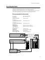
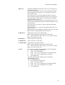
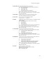
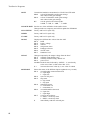
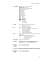
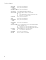
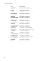
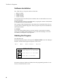
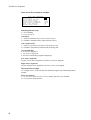
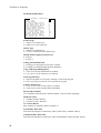
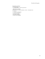
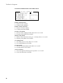
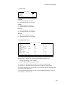
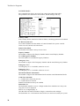
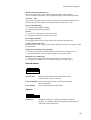
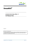
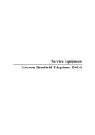
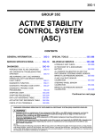
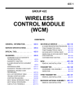
Test/Service Programs
Ericsson Mobile Phone EF738
Test/Service Programs
2
Test/Service Programs
Contents
Test Equipment_____________________________________ 5
Recommended Instruments _________________________________ 5
Other Equipment__________________________________________ 6
Test Program_______________________________________ 7
How to Use _______________________________________________ 7
Initiating the Test Program ______________________________________ 7
Return to TEST INPUT ________________________________________ 7
Exit ________________________________________________________ 7
Individual Test Options ____________________________________ 8
Overview of the Test Program __________________________________ 15
ETACS Service Program ____________________________ 17
Hardware Requirements___________________________________
Software Installation ______________________________________
Starting the Program _____________________________________
The Programming Cycle___________________________________
Using the Menus _________________________________________
17
18
18
19
19
How to Select _______________________________________________
The Functions _______________________________________________
File_____________________________________________________
Edit ____________________________________________________
Short Numbers____________________________________________
Options _________________________________________________
19
20
20
21
31
31
Re-Programming a Telephone ______________________________ 32
Contents of Saved Short Number Files _______________________ 32
Keypad NAM Programming _________________________ 33
Long NAM Programming__________________________________ 34
Programmable Parameters _____________________________________ 34
Programming Instructions _____________________________________ 36
Default Values ______________________________________________ 38
Quick NAM Programming _________________________________ 40
Programmable Parameters _____________________________________ 40
Programming Instructions _____________________________________ 41
Default Values ______________________________________________ 42
Flash Programming ________________________________ 43
Introduction _____________________________________________ 43
Hardware Requirements___________________________________ 43
Software Setup ___________________________________________ 43
Installing the Shell Program ____________________________________ 44
Installing a Flasher Program____________________________________ 44
Flash Operation __________________________________________ 45
Hardware Setup _____________________________________________ 45
Flashing Instructions__________________________________________ 45
3
Test/Service Programs
4
Test/Service Programs
Test Equipment
The type of equipment required for service on the Ericsson Mobile Phone EF738 is
listed below and includes instruments, tools, and other hardware.
Descriptions of the programs for test, service, NAM programming, ESN transfer,
and software upgrading are also included in the following subsections.
Recommended Instruments
Instrument
Recommended Unit
Alternative 1:
Radio Test System
Marconi 2960
lternative 2:
Communication Test Set
Schlumberger 4031
Alternative 3:
Communications Test Set
Schlumberger 4015
Alternative 4:
Radio Test Set
Signalling Unit
Rohde & Schwarz CMS 52
Rohde & Schwarz CMS-B13
Other alternatives:
Oscilloscope
Multimeter
Digital Voltmeter
Power Supply Unit
Tektronix 2235
Hewlett-Packard 3468A
Fluke 8060A
Power Box EK030-10
POWER SUPPLY
GROUND CABLE (black)
SUPPLY CABLE (red)
GROUND SUPPLY
ANTENNA CABLE
ANTENNA ADAPTER
INSTRUMENT (FRONT)
RF IN/OUT
IN-AUDIO-OUT
C
A
R
C
R
A
D
L
E
DB-9
IN - AF - OUT
DB-15
D
U
M
M
Y
B
A
T
T
E
R
Y
LPC
102 280
KRY 101 1612/2
5
Test/Service Programs
Other Equipment
Equipment
ETACS Service Program
Programming Interface
Connection Cable
Adapter
Car Cradle
Test Handset
Antenna Cable
Antenna Cable Adapter
Dummy Battery
Service Adapter Kit
- Test Interface Box
- Audio Box
- Power Supply 110V
- Power Supply 220V
Ordering Number
NTZ 112 311
KRY 101 1135/10
LPC 102 280
KRY 109 1001/72
NTZ 112 210
NTZ 112 294
RNT 403 012/003
NTZ 112 310
LPC 102 280
KRY 101 1612/51
KRY 101 1612/54
KRY 101 1612/55
Standard tools and soldering equipment must also available
Note: When servicing mobile telephones, it is most important that a bench earthing
network is used to protect sensitive components against electrostatic discharge
(ESD).
6
Test/Service Programs
Test Program
How to Use
This document will describe the use of the built-in test program for the EF738.
After the more extensive descriptions found in Individual Test Options, an overview
follows in the form of a table with data referring to the different options.
This table will become a handy alternative after having some experience of the test
program.
Initiating the Test Program
The test program is initiated from the special test handset;
by holding down the M button and pressing 90 40 59 or
by pressing 90 40 59 followed by M M
However, if the Test Program Enter function is enabled in the telephone, the program can be initiated and run directly from the keypad by pressing the same
sequence (M = MENU).
When the phone enters the test mode, the hardware becomes initialized and the text
TEST INPUT appears in the display.
To step forward and backwards in the test program; press SEND and RCL.
To choose a specific test; press its number followed by the # button.
Return to TEST INPUT
Press the C or M button to return to the input mode where the TEST INPUT prompt
is displayed.
Exit
To exit from the test program; select test option 99 and press the # button.
7
Test/Service Programs
Individual Test Options
A list describing the use of the test program options follows below.
A summary of the test options and possible parameter values is given as well.
1 CH NUMBER Setting of channel number
Choose any chanel in the ETACS system (0-600, 1329-2047).
Default setting is channel 1.
To change channel number; enter a 4-digit decimal number followed by #.
Use * and # to step backwards/forwards.
Channel number and signal strength are displayed.
8
2 TX POWER
Sets the transmitter on and offF and determines the output power
level.
8
off
7
power level 7; minimum output power
6
power level 6
5
power level 5
4
power level 4
3
power level 3
2
power level 2; maximum output power
When the power reduction function is activated in menu 76,
power level 2 will be displayed as ‘S’.
When the extra power option in menu 76 is activated,
power level 2 will be displayed as ‘X’.
4 FLASHER
Used only when loading the program into a terminal.
5 PWR CAL
Calibration of power levels.
Transmitter is turned on and tuned to the calibration channel.
Modify the power levels with the following keys:
# / * increases/decreases the power level
M+S stores the value and steps to next power level;
transmitter is turned on
M+# starts calibration and displays power level;
steps forward to next power level (2->3->...->7->2).
C
turns off TX, restores channel no., returns to menu 0.
6 TX DETECT
Performs two simple transmitter tests: a general Go/NoGo transmitter test and a transmitter leakage test.
To start the test, press any key except C.
The result is displayed when the test is finished:
FF both tests passed
01
general transmitter test failed
02
leakage test failed
7 TX SENS
Factory and level 5 repair only
Test/Service Programs
9 RF CAL
Calibrates the RSSI levels based on the level of the signal currently being received.
The value determined for each level is the minimum strength
signal for that level, averaged over 16 readings to provide a
more reliable value.
The value for level 0 is used to update the Receiver Carrier
Detect (RXCD) such that signals below this level are ignored.
This value (plus a fixed offset) also determines the minimum
signal threshold for the AFC.
When the received signal is below this threshold, the AFC provides TCXO compensation based on a default temperature compensation table.
The values for level 1 and 5 are used to determine the RSSI
graph to display.
The values for level 2, 3 and 4 are interpolated from these two
reference levels.
M+# displays the next RSSI level number and its current value
M+S reads an averaged RSSI value and stores it
10 RX SENS
Adjustment of the receiver audio output
M+# enables calibration and echoes the initial value
# / * increases/decreases the value by 1; new value is echoed
M+S stores the current value
11 KEYPAD
Factory and level 5 repair only
13 BANDGAP
Factory and level 5 repair only
14 AUDIO DEV Adjustment of the audio deviation
M+# enables calibration and echoes the initial value
# / * increases/decreases the value by 1; new value is echoed
M+S stores the current value
15 AFC
Sets the AFC operating mode and displays AFC information
0
only temperatue compensation
1
temp. + age compensation
2
temp. + age + freq. compensation, smoothed (default)
3
temp. + age + freq. compensation, no smooth
4
no compensation
Any other code entered in handset mode will display:
ABCCDDEEFF where
A = AFC operating mode
0 only temperatue compensation
1 temp. + age compensation
2 temp. + age + freq. compensation, smoothed (default)
3 temp. + age + freq. compensation, no smooth
4 no compensation
9
Test/Service Programs
B = AFC state
1 waiting for signal;
(no valid RSSI, compensate for temp. or temp. + age)
2 acquiring lock;
(RSSI good, use whole freq. error for 1.5 sec for fast lock)
3 locked (RSSI good, use smoothed freq. compensation)
4 freeze lock ( RSSI temporarily lost, compensate for
temp + age + (frozen) freq. error for up to 30 sec.)
5 locked using short count;
(RSSI good, use smoothed freqcompensation);
only entered when current savings is active;
short freq. measurements is used to find freq. error compensation
6 entered when DRX has started;
compensate for temp. + age + (frozen) freq. error.
CC total compensation
DD temperature table component
EE age component
FF frequency error component
10
18 DAC2CAL
Calibration of the VCTCXO.
M+# enables calibration and echoes the initial value
# / * increases/decreases the value by 1; new value is echoed
M+S stores the current value
During the calibration the AFC is in ‘Temperature only compensation mode’ (Tp-15:0)
Upon exiting the calibration the AFC returns to its previously
selected operating mode.
19 RX SAT
Factory and level 5 repair only
20 AUDIO
Sets the audio paths in the audio circuit
Key TX-audio
RX-audio
0
muted
muted
1
unmuted
muted
2
muted
unmuted
3
unmuted
unmuted
21 HANDSET
Sets the audio paths in the handset.
0
microphone off, earphone off, loudspeaker off (default)
1
microphone on, earphone on, loudspeaker off
2
microphone off, earphone off, loudspeaker on
22 TX SAT
Controls the SAT tone switch and TX SAT deviation.
0
generate 5970 Hz SAT
1
generate 6000 Hz SAT
2
generate 6030 Hz SAT
3
no SAT generated
4
SAT tone switch setting = ON
5
SAT tone switch setting = OFF
M+# enables calibration and echoes the initial value
# / * increases/decreases the value by 1; new value is echoed
M+S stores the value
Test/Service Programs
23 MANCH OUT Controls the wideband data and deviation
To transmit these data the transmitter must be switched on.
0
off - no data output)
1
8kHz output; ones
2
8kHz output; zeros
3
hardcoded idle frame; 0101010101
M+# enables calibration and echoes the initial value
# / * increases/decreases the value by 1; new value is echoed
M+S stores the value
24 MANCH IN
Displays the latest received data from the base station.
The value is displayed each time a key is pressed.
25 VOLUME
Sets the earpiece and loudspeaker volume.
Possible values: 0 - 7 (default: 3)
26 DTMF
DTMF tones consist of a lower frequency in combination with a
higher frequency.
The test enables listening to either or both as follows:
0
low frequency
1
high frequency
2
both frequencies.
# / * scroll forwards/backwards to next/previous DTMF tone
M+# enables calibration and echoes the initial value
# / * increase/decrease the value by 1; new value is echoed
M+S stores the value
27 TX SOURCE Sets the TX audio paths in the audio circuit.
Also possible to adjust the levels of the different audio paths.
0
external line input, ATMS (default)
1
internal MIC
2
internal MIC with MicAmp gain
M+# enables calibration and echoes the initial value
# / * increases/decreases the value by 1; new value is echoed
M+S stores the value
28 EARPIECE
Sets the earpiece mute switch in the audio circuit to allow for
adjustment of the earpiece sensitivity values.
0
1
2
internal earpiece disconnected
internal earpiece connected
audio sent out AFMS on system connector (default)
internal earpiece and AFMS can both be adjusted
M+# enables calibration and echoes the initial value
# / * increases/decreases the value by 1; new value is echoed
M+S stores the value
29 COMP
Selects compander or linear mode
M+# displays the current compander settings
M+0 linear mode (default)
M+1 companding mode
11
Test/Service Programs
30 HF
Controls the handsfree attenuation level for RX and TX audio
M+0
selects RX handsfree audio gain settings
and echoes initial gain settings
M+1
selects TX handsfree audio gain settings
and echoes initial gain settings
0-7
sets the gain for the selected path:
0=0dB, 1=-7dB, 2= -14dB, ... 7=-49dB
32 SOFTLIMIT Sets the use of the softlimiter in the audio circuit.
Changes made are temporary and will not update the EEPROM.
12
35 COUNTRY
Factory and level 5 repair only
36 BER
Factory and level 5 repair only
37 OMC
Factory and level 5 repair only
38 ADC
Displays the different hex values from the ADC
M+1
RSSI
M+2
battery voltage
M+3
unused
M+4
temperature sense
M+5
bandgap reference
M+6
current sense
M+7
handsfree level
39 DAC
Changes temporarily the output voltage from the DAC.
M+1
normally controlled by AFC
M+2
normally trimmed using ‘MENU 18’
M+3
power level
xxx M+# decimal value followed by ‘MENU + #’ sent directly
to the active DAC (valid values: 000 - 255)
#/*
increases/decreases value by 1; new value is echoed
40 INPORT
Shows the status of the different inports (updated every second)
M+1
external audio connection detected
0 = input high
1 = input low
M+2
state of CPU port 2
M+3
flip status
0 = flip closed
1 = flip open
M+4
transmitter status
0 = transmitter off
1 = transmitter on
M+6
external handsfree detected
0 = input low
1 = input high
M+7
receiver carrier detect
0 = RSSI < sensitivity limit
1 = RSSI > sensitivity limit
#
immediately reads the selected port
Test/Service Programs
41 OUTPORTS
Shows the status of the selected outport
First select a digital outport:
M+1+0 VRX
M+1+1 VTX, Note! VRX must be on!
M+1+2 power down VCO
M+1+3 unused
M+1+4 SWDC
M+1+5 MPD2
M+1+6 FMPD1
M+1+7 unused
M+1+8 temperature
M+2
ICTRL
M+3
MUTE
M+4
green LED
M+5
red LED
M+6
back light
Then select the state:
0
set output low
1
set output high
42 DSCR
Turns the discriminator and multiplier on and off
0
discriminator off
1
discriminator on (default)
43 BAR
Tests the different tones of the phone
0
continous ringing signal at maximum volume
1
continuos alarm signal
2
click signal single pulse
3
error signal single pulse
4
continuous 3kHz ringing tone
45 LCD
Tests the different segment and icons of the display as five different patterns
M+digit (1-5)shows the selected pattern no. (1-5)
#
shows all patterns continuously
starting with pattern no. 1
C or S
terminates the test
46 PWR DOWN Factory and level 5 repair only
47 SW REV
Displays the software, revision and ESN inside the terminal.
Press any key to show software name and revision.
Additional pressure of any key will show the ESN.
48 SYNTH
Factory and level 5 repair only
49 RX PWR
MODE
Factory and level 5 repair only
50 GUARANTEE Press any key to display year and month when warranty/guarantee was activated and the length (months)of the warranty period
53 SYNT I SET
Factory and level 5 repair only
54 EEPROM
INIT
Factory and level 5 repair only
13
Test/Service Programs
60 SYNTH
Factory and level 5 repair only
61 AUDIO
CIRCUIT
Factory and level 5 repair only
62 RADIO CTRL Factory and level 5 repair only
74 TCA TEST
Checks the ETACS combining algorithm
76 BATT SAVE
Controls the reduced and extra power functions
0
off
1
power reduction invoice channel (power level 2 only)
2
extra power (power level 2 only)
77 EEDATA
Factory and level 5 repair only
79 PIN
Factory and level 5 repair only
91 EEPROM
DUMP
Factory and level 5 repair only
92 EEPROM
LOAD
Factory and level 5 repair only
96 COLD START Clears the RAM, exits service & test mode, and powers up in
‘terminal charge only mode’
#
exit service & test mode; power up in normal mode
M+# exit service & test mode; power up in charge only mode
14
97 FLASH
CHSUM
Calculates the checksum of the flash memory
#
2 bytes checksum will be displayed
98 ERROR
Factory and level 5 repair only
99 EXIT
Press # to exit the service program
Test/Service Programs
Overview of the Test Program
Menu
Possible Values
1 CH NUMBER
0-600, 1329-2047
2 TX POWER
8 (off) - 2 (maximum power)
4 FLASHER
only used when loading program into terminal
5 PWR CAL
calibration of power levels
6 TX DETECT
simple test of transmitter
7 TX SENS
factory and level 5 repair only
9 RF CAL
RSSI calibration
10 RX SENSE
adjustment of receiver audio output
11 KEYPAD
factory and level 5 repair only
13 BANDGAP
factory and level 5 repair only
14 AUDIO DEV
adjustment of maximum audio deviation
15 AFC
sets AFC operating mode and displays AFC information
18 DAC2CAL
calibration of VCTCXO
19 RX SAT
factory and level 5 repair only
20 AUDIO
sets audio paths in audio circuits
21 HANDSET
sets audio paths in handset
22 TX SAT
controls SAT tone switch and TX SAT deviation
23 MANCH OUT
controls wideband data and deviation
24 MANCH IN
displays latest received data from base station
25 VOLUME
sets earpiece and loudspeaker volume
26 DTMF
DTMF tones
27 TX SOURCE
sets TX audio paths in audio circuit
28 EARPIECE
sets earpiece mute switch in audio circuit
29 COMPAND
selects compander/linear mode
30 HF
controls handsfree attenuation level for RX and TX audio
32 SOFTLIMIT
sets use of softlimiter in audio circuit
35 COUNTRY
factory and level 5 repair only
36 BER
factory and level 5 repair only
37 OMC
factory and level 5 repair only
38 ADC
displays different hex values from ADC
39 DAC
changes temporarily output voltage from DAC
40 INPORTS
shows status of different inports
15
Test/Service Programs
16
Menu
Possible Values
41 OUTPORTS
selects status of selected outport
42 DISCR
turns discriminator/multiplier on/off
43 BAR
tests different tones of phone
45 LCD
tests different segments and icons of display
46 PWR DOWN
factory and level 5 repair only
47 SW REV
displays software, revision and ESN inside terminal
48 SYNTH
factory and level 5 repair only
49 RX PWR MODE
factory and level 5 repair only
50 GUARANTEE
warranty information
53 SYNT I SET
factory and level 5 repair only
54 EEPROM INIT
factory and level 5 repair only
60 SYNTH
factory and level 5 repair only
61 AUDIO CIRCUIT
factory and level 5 repair only
62 RADIO CTRL
factory and level 5 repair only
74 TCA TEST
checks ETACS combining algorithm
76 BATT SAVE
controls reduced and extra power functions
77 EEDATA
factory and level 5 repair only
79 PIN
factory and level 5 repair only
91 EEPROM DUMP
factory and level 5 repair only
92 EEPROM LOAD
factory and level 5 repair only
96 COLD START
powers up in ‘terminal charge only mode’
97 FLASH CHSUM
calculates checksum of flash memory
98 ERROR
factory and level 5 repair only
99 EXIT
press # to exit service program
Test/Service Programs
ETACS Service Program
The ETACS Service Program is a tool used for entering the initializing customer
parameters into the EEPROM of the Ericsson mobile phone EF738.
This description of the ETACS Service Program includes information on:
• hardware requirements
• software setup
• programming instructions
Hardware Requirements
The following equipment is required when using the ETACS Service program for the
EF738 Ericsson mobile phone:
•
•
•
•
•
PC with Windows 3.1 or Windows 95 operating system
COM port (COM1 - COM2) available on the PC
Programming cable, KRY 101 1135/10 R1A
Programming interface, NTZ 112 311
Adapter, 25- to 9-pin; for PC equipped with a 9-pin COM-connector
( not supplied by Ericsson)
.
Fully
charged
battery
NTZ 112 311
3
4
1
2
KRY 101 1135/10 R1A
17
Test/Service Programs
Software Installation
The ETACS Service Program consists of four files:
•
•
•
•
SPEP1361.EXE
TYPE1361.CFG
TYPE1361.EDT
TYPE1361.MNU
The program can be run directly from a diskette, but it is adviseable to have it run
from the hard disk.
Simply install the software on the hard disk by copying the contents of the diskette
to a suitable directory on the hard disk.
The copying of files mentioned above describes how to install the ETACS Service
Program from a standard floppy disk, but the program may become distributed in
other media formats.
CAUTION!
Use a fully charged phone battery, since the interface is powered by the phone.
Using an even slightly discharged battery may result in misreadings, even if the
Low Battery warning has not yet appeared.
Starting the Program
Turn the phone On.
Start the program by double-clicking the file SPEP1361.EXE in the File Manager /
Explorer, and the following picture appears on the screen:
File
Edit
Short Numbers
Options
SELECT COM PORT
1
Press digit 1 to use COM1:
2
Press digit 2 to use COM2:
Esc
Press ESC to continue.
Select the serial port (COM1 or COM2) where the programming interface is connected, as instructed on the screen.
18
Test/Service Programs
The Programming Cycle
Details of the different entries are given in ‘Using the Menus’.
Below is a brief description of the main events.
After selection of the COM port the Subscriber Data editing window is automatically displayed. Most customers will require data to be entered in this window only.
Move the cursor by the arrow keys of the PC, or click the mouse on the respective
field of the window.
Press the Esc key to return to the main menu on the top row of the screen.
SUBSCRIBER DATA
Subscriber No. part1
0836
Subscriber No. part2
123456
Mobile Stat. Id. No.
123456
ACCOLC
5
Home Traffic AID
0803
Guarantee Start,mmyy
1097
Guarantee Length,mm
12
Lock Code
0000
The service program will fetch ‘today’s date’ from the system clock of the PC.
Check and (if necessary) correct the date before starting the programming.
When ready to program the telephone, i.e. transfer data into the EEPROM:
• Press F2 while keeping the ALT-key depressed (ALT+F2)
• Confirm by pressing the Y-key
After the programming the result can be verified by pressing ALT+F3.
To exit the program, press ALT+X.
Using the Menus
How to Select
Press Esc to reach the menu.
From a 'Data edit window' it is also possible to go directly to a sub-menu by holding
down the ALT key and pressing the highlighted letter in the main menu, e.g.
ALT+F to go to File functions.
Move the selection bar (reverse video) to the left or right by the keypad arrow keys
to select a sub-menu and press Enter to open it. The functions in the sub-menu are
selected by moving the selection bar up or down using the arrow keys.
Press Enter to activate the selected function, or Esc to return to the main menu.
Sub-menus and functions can also be reached by clicking with the mouse.
19
Test/Service Programs
The Functions
NOTE! Defaults are printed in italic.
File
The ‘File’ sub-menu includes the functions listed below:
File
Read
Burn
Verify
Save
Load
Reset PIN
Activate DRX
Deactiv. DRX
EXit
Alt
Alt
Alt
Alt
Alt
Alt
Alt
Alt
Alt
F1
F2
F3
F5
F6
F7
F8
F9
X
Read
Transfers the contents of the EEPROM to the computer memory.
CAUTION! When using this function, make sure to reload the
configuration file before programming other phones, as incorrect data inadvertently might be programmed.
Burn
Programs the phone with the Subscriber, Country and System
data that has been entered into the PC memory.
Verify
Comparison between the PC memory and the phone.
Save
This command has two different functions:
1. Creates a configuration file which is automatically loaded at
each program start.
The file name must be manually changed to TYPE1361.CNF.
All data from the edit windows are saved.
Guarantee Start is set to ‘today's date’ by the system clock.
2. Saves the data in the phone before service.
Data in the edit windows is saved if the file name is other
than TYPE1361.CNF.
Default name is STATION1.SAV.
Load
Reloads a configuration file.
Reset PIN
Resets the PIN to 0000.
Activate DRX
Activates the Discontinuous Reception feature.
CAUTION! May deteriorate the performance of the phone,
if DRX is not supported by the system
Deactivate DRX Deactivates the Discontinuous Reception feature.
Exit
20
Quit the program.
Test/Service Programs
Edit
When leaving the ‘File’ menu the ‘Subscriber Data’ edit window is displayed.
After pressing Esc the ‘Edit’ sub-menu is reached and the editing windows listed
below can be accessed:
Edit
Subscriber Data
Misc MMI Features
Sounds & General
Call Set & CallData
System & Services
Sys Opt & Restrict.
Languages
NAM & Quick NAM
Country data 1
Country data 2
Country data 3
Country data 4
SUBSCRIBER DATA
SUBSCRIBER DATA
Subscriber No. part1
0836
Subscriber No. part2
123456
Mobile Stat. Id. No.
123456
ACCOLC
5
Home Traffic AID
0803
Guarantee Start,mmyy
1097
Guarantee Length,mm
12
Lock Code
0000
Subscriber No. Part 1/Part 2
The Subscriber No. (shown in certain menues and at power on) is information
intended for the user and is not used by the system.
Mobile Station Identification No.
The 6 least significant digits of the international mobile station number,
usually identical to the 6 least significant digits of the subscriber number.
ACCOLC
The Access Overload Class is normally the second last digit of the Mobile Station
Identification No.
Home Traffic AID
The Home Traffic Area Identification is entered as a hexadecimal code.
Guarantee Start, mmyy
Is read from the PC's system clock at program start, but can be manually altered.
Guarantee Length, mm
To be used in conjunction with the Guarantee Start.
Lock Code
The subscriber's four-digit lock code which must initially be set to 0000 to comply
with the information of the User's Manual.
21
Test/Service Programs
MISCELLANEOUS MMI FEATURES
MISC MMI FEATURES
Roam. indicat. type
Auto Retry
Call Count Feature
Arrow Indication
Left Arrow Segments
Right Arrow Segments
Int. lock digits
Three level menu
N
Y
Y
1
22C0
0251
0A
Y
Roaming Indicator Type
Y = Icon flashing
N = Icon steady on
Auto Retry
Y = Enables Automatic Retry when network is busy
N = Disables Automatic Retry when network is busy
Call Count Feature
Y = Enables registration of unanswered incoming calls
N = Disables registration of unanswered incoming calls
Arrow Indication
0: no arrow is displayed
1: one arrow is displayed
2: one arrow followed by hyphen is displayed
Left Arrow Segments
Layout of Left Arrow Segments: 22C0HEX, (not to be changed)
Right Arrow Segments
Layout of Right Arrow Segments: 0251HEX, (not to be changed)
International Lock Digits
No. of digits as hex. code to define the minimum length of an international phone
number
Three Level Menu
Y = 3-level user menu structure is set to comply with the User’s Manual
N = 2-level user menu structure
22
Test/Service Programs
SOUNDS & GENERAL
SOUNDS & GENERAL
Ring Vol Menu
Y
Ringtone Menu
Y
Keysound Menu
Y
Silent Menu
Y
Not used, set to N
N N N
Backlite Menu
Y
Greeting Menu
Y
Language Menu
Y
Reset Menu
Y
Mem Used Menu
Y
Keylock Menu
Y
Not used, set to N
N N
Ring Volume Menu
Y = Ringing volume selection ‘Low/Med/High/Step/Silent’ enabled
N = Ringing volume selection disabled.
RingTone Menu
Y = Ringing tone selection ‘Low/Med/High/Mixed/Scale/Fast/Melodies’ enabled
N = Ringing tone selection disabled.
KeySound Menu
Y = Key sound selection ‘Burst/Continuous/Click/Silent’ enabled
N = Key sound selection disabled
Silent Menu
Y = Silent Mode selection ‘Off/On’ enabled
N = Silent Mode selection disabled
BackLite Menu
Y = Backlight selection ‘Off/On 10sec/On 20sec’ enabled
N = Backlight selection disabled
Greeting Menu
Y = Greeting String (at power on) choice enabled
N = Greeting String disabled
Language Menu
Y = Language selection ‘English/Espanol/Italiano/Deutsch/Melayu’ enabled
N = Language selection disabled
Reset Menu
Y = Reset option ‘Reset All’ enabled
N = Reset option disabled
Memory Used Menu
Y = Memory Used Menu is accessable
N = Memory Used Menu not accessible
KeyLock Menu
Y = Key lock selection ‘Unlock/Lock’ enabled
N = Key lock selection disabled
23
Test/Service Programs
CALL SET & CALL DATA
CALL SET & CALLDATA
Fastdial Menu
Y
Flip Menu
Y
Answ Opt Menu
Y
Minder Menu
Y
Tonesend Menu
Y
Acc Tone Menu
Y
N
Air Info Menu
Call Type Menu
Y
LastTime Menu
Y
LastChar Menu
N
Tot Time Menu
Y
Tot Char Menu
N
Call Cnt Menu
Y
Not used, set to N
N N N
FastDial Menu
Y = Fast Dial (one-key-dial) selection ‘Off/On’ enabled
N = Fast Dial selection disabled
Flip Menu
Y = Flip (answer/end-call) selection ‘Off/On’ enabled
N = Flip answer/end-call disabled
Answering Option Menu
Y = Answering method selection ‘Any Key/Send Only’ enabled
N = Answering method selection disabled
Minder Menu
Y = Minder (minute beep) selection ‘Off/On’ enabled
N = Minder selection disabled
Tone Send Menu
Y = Tone Send (DTMF when key pressed during call) selection ‘Off/On’ enabled
N = Tone Send selection disabled
Access Tone Menu
Y = Access Tone (outgoing call established) selection ‘Off/On’ enabled
N = Access Tone selection disabled
Air Info Menu
Y= Air Info (duration or charge) display selection ‘Air Time/Call Charge’ enabled
N = Air Info disabled
Call Type Menu
Y = Call Type charge (out or out/in) display selection ‘Only Out/Out and In’enabled
N = Call Type charge display selection disabled
Last Time Menu
Y = Last Time (duration of last call) display selection enabled
N = Last Time display selection disabled
Last Charge Menu
Y = Last Charge (no. of charge units for last call) display selection enabled
N = Last Charge display selection disabled
Total Time Menu
Y = Total Time (since counter reset) display selection enabled
N = Total Time display selection disabled
24
Test/Service Programs
Total Charge Menu
Y = Total Charge (since counter reset) display selection enabled
N = Total Charge display selection disabled
Call Count Menu
Y = Call Count (no. of in/out-going calls since reset) display selection enabled
N = Call Count display selection disabled
25
Test/Service Programs
SYSTEM & SERVICES
SYSTEM & SERVICES
ETACS Type
ITACS Type
MS supp. TACS level
Call Line Identific.
Long NAM Prog. Entry
Test Program Entry
Country Menu Entry
Rescan Time, minutes
Handset Feature
No of Auto Retries
Sys. Busy Wait Time
Called side BW Time
Keypad Layout Type
ABC Indicator Debug
Not used, set to 00
Y
N
1
Y
N
N
Y
5
N
3
0A
1E
1
0
00
ETACS Type
Y = Phone is an ETACS type
N = Phone is a TACS only type
ITACS Type
Y = Phone is an ITACS type
N = Used in combination with ETACS type
Mobile Station supported TACS level
0: if TACS
1: if TACS-2
Calling Line Identification
Y = Calling Line Identification functions enabled
N = Calling Line Identification functions disabled
Long NAM Programming Entry
Y = User access to the NAM menu is enabled
N = User access to the NAM menu is disabled
Test Program Entry
Y = The test program is accessed by entering a code on the keypad
N = The test program cannot be accessed from the keypad
Country Menu Entry
Y = User access to the Country Menu is enabled
N = User access to the Country Menu is disabled
Rescan Time, minutes
No. of minutes until a Rescan is started (default: 5 minutes) after signalling
Handset Feature
Y = Handset Feature enabled
N = Handset Feature disabled
No. of Auto Retries
Max. number of Automatic Retries (default: 3)
System Busy Wait Time
Time between attempts in Auto Retry when system is busy (default: 0AHEX)
Called Side Busy Wait Time
Time between attempts in Auto Retry when called number is busy (default: 1EHEX)
26
Test/Service Programs
Keypad Layout Type
0: Not applicable
1: New international alpha keypad layout
ABC Indicator Debug
Enables the use of special indicators, ‘ABC’, for internal tests:
0: not used
1: NAM system indication
2: Accessory indication
3: Data/Voice mode
4: TX power indication
5: Power save indication
27
Test/Service Programs
SYSTEM OPTIMIZATION & RESTRICTIONS
SYS OPT & RESTRICT.
Enable NAM Selection Y
Enable Country Sel.
Y
Not used, set to N
N N N N N N
Sec Code Menu
Y
Not used, set to N
N N N N N N N
Mem Only Menu
Y
Y
No Calling Menu
No Inter Menu
Y
Auto Lock Menu
Y
Not used, set to N
N N N N
Enable NAM Selection
Y = NAM selection enabled
N = NAM selection disabled
Enable Country Selection
Y = Country selection enabled
N = Country selection disabled
Security Code Menu
Y = Security Code (4-digit personal code) Menu is accessible
N = Security Code Menu not accessible
Memory Only Menu
Y = Memory Only (calls from mem. pos. 1-10 only) Menu is accessible
N = Memory Only Menu not accessible
No Calling Menu
Y = No Calling (receive only) Menu is accessible
N = No Calling Menu not accessible
No Inter Menu
Y = No Inter (no international calls) Menu is accessible
N = No Inter Menu not accessible
Auto Lock Menu
Y = Auto Lock (phone locked at power-up) Menu is accessible
N = Auto Lock Menu not accessible
28
Test/Service Programs
LANGUAGES
LANGUAGES
Not used, set to Y
Spanish
Italian
Deutsch
Melayu
Not used, set to N
Y
Y
Y
Y
Y
N N N
Spanish
Y = Spanish language selectable
N = Spanish language not selectable
Italian
Y = Italian language selectable
N = Italian language not selectable
Deutsch
Y = German language selectable
N = German language not selectable
Melayu
Y = Malayan language selectable
N = Malayan language not selectable
NAM & QUICK NAM
NAM & QUICK NAM
ESN
Y
CODE
Y
ROAM TYPE
Y
CHARGE
Y
CHAN, FCCHA, FCCHB
Y Y Y
BANDA, BANDB
Y Y
NO EMERG
Y
EMERG 1, EM.2, EM.3
Y Y Y
ENQUIRY
Y
INTER PREF
Y
NAM
Y
IMSI, SUBN
Y Y
SYSTEM
Y
AIDH, FPCH, ROAM
Y Y Y
ACCOLC, LOCAL, EXT
Y Y Y
Not used, set to Y/N
Y Y Y Y Y Y Y
Y
N
N
Y
N
N
N
N
N
Y
N
Y
N
Y
N
N
N N
N
N N
Y
N N
N N
N N N N N N
The table above displays the various programmable parameters for:
• NAM programming (center column)
• Quick NAM programming (right column)
By entering a Y, the parameter becomes accessible for programming.
By entering a N, the parameter becomes not accessible for programming.
The default settings for the accessibility of the NAM and Quick NAM parameters
are as listed in the table above.
For more detailed information, refer to ‘Keypad NAM Programming’ which is
found further on in this section.
29
Test/Service Programs
COUNTRY DATA
The example below shows one out of four country dependent data tables.
The parameters are identical for all countries, but the settings will vary.
COUNTRY DATA 1
Country Name
UK
CC Data, System A B
0023 21 0323 21
Station Class Mark
13
Enquiry Number
3 192
No of Emergency No.s
2
Emergency no. 1
3 999
Emergency no. 2
3 112
Emergency no. 3
0
Intern. Prefix Info
2 00
NAM User Selectable
Y
N
Subscriber No.
0836123456
0836123456
Mobile Stat. Id. No.
123456
123456
ACCOLC, AID
5 0803
5 0803
Inter System Roaming
N
N
System
A
A
First Paging Channel
0023
0023
Country & Netw. Code
234 A
234 A
Send Ext. MS Number
N
N
Resp. to Local Mess.
N
N
Country Name
If the Country Name contains less than ten letters, remaining positions can be blank.
CC Data, System A B
First control channels and the number of control channels for system A and B.
Values are to be entered in decimal form.
Station Class Mark
The Station Class Mark is always set tot 13HEX.
Enquiry Number
The number of digits of the Enquiry Number and the actual Enquiry Number.
No. of Emergency Numbers
The total number of available Emergency Numbers.
Emergency No. 1
The number of digits of the Emergency Number and the actual Emergency Number.
Emergency No. 2
As Emergency No.1, if available, otherwise set to 0.
Emergency No. 3
As Emergency No.1, if available, otherwise set to 0.
International Prefix Information
The number of digits of the International Prefix and the actual International Prefix.
NAM User Selectable
Y = NAM can be selected by the user
N = NAM cannot be selected
Note! First NAM must always be enabled
Subscriber No.
The Subscriber Number is a max. 10-digit number from which the user may want
only part of it to be displayed.
Enter A for 10-digit display, or
enter 0 to 9 for the reduced number of digits, counted from the end digit.
The Subscriber No. is information aimed for the user and is not used by the system.
30
Test/Service Programs
Mobile Station Identification No.
The 6 least significant digits of the international mobile station number,
in most countries equal to the 6 least significant digits of the subscriber number.
ACCOLC, AID
The Access Overload Class, normally the last digit of the Mobile Station Id. No.,
followed by the Home Traffic Area Identification entered as hex. code.
Inter System Roaming
Y = Inter System Roaming enabled
N = Inter System Roaming disabled
System
A = System A is the home system in the NAM
B = System B is the home system in the NAM
First Paging Channel
First paging channel in the present NAM to be entered in decimal form.
Country & Network Code
Mobile Country Code (3 digits), followed by Mobile Network Code (1 digit), for the
present NAM.
Send External Mobile Station Number
Y = Phone must send the extended address word when accessing the system
N = Extended address word not required when accessing the system
Response to Local Message
Y = Phone must respond to local control messages sent on the FOCC
N = Response not required to local control messages sent on the FOCC
Short Numbers
Short Numbers
Save To Disk
Load From Disk
Clear Mobile
Save To Disk
Reads the short numbers from the telephone and
transfers them to a file, see below.
Load From Disk Reads short numbers from a file and stores (burns)
them in the phone.
Clear Mobile
Clear all short numbers in the phone.
Options
Options
Com Port
COM Port
Possible to change the COM-port whithout leaving the
program, for example, when having programming interfaces
connected to both COM-ports.
31
Test/Service Programs
Re-Programming a Telephone
When making changes to a telephone that has already been programmed,
first read the EEPROM by pressing ALT+F1.
Then perform the desired changes and program the EEPROM by pressing ALT+F2.
Verify by pressing ALT+F3.
Note: Make sure that the configuration file has been reloaded before programming
other phones. Otherwise incorrect data may inadvertently be programmed.
Contents of Saved Short Number Files
The ‘Save’ file is a normal text file which may be edited by any word processor or
text editor as an ASCII text file. It is possible to create a file independently from the
program, and then use the program for transfer to the telephone. The file does not
have to list the short numbers in any particular order, and it is not necessary to supply all 99 numbers.
For example, it is possible to create a file with only three short numbers at pos. 21,
22, and 23, and add these to a phone that already has some numbers programmed.
Each line of the file should have the following form:
1. Two digits representing the Short Number positions from 01 through 99.
2. Name of the subscriber, maximum 10 characters, letters and digits.
3. Telephone number of no more than 16 or 32 characters (system dependent).
Digits 0 - 9, * , and # are allowed.
Example:
01 ERICSSON 0094646193000
02 JOHN DOE 12345678
03 TRANSFER *21*9171234567#
Lines containing the positions only will erase the shortcodes, for example:
04
05
06
A line containing text only ‘NO NUMBERS’ is a comment and will not cause any
programming of the telephone.
32
Test/Service Programs
Keypad NAM Programming
The Keypad NAM (Number Assignment Modules) Programming includes not only
the NAM parameters but also some functionally related parameters as well as country dependent parameters.
Two different Keypad NAM Programming modes are available:
• Long NAM (non-user selectable by default)
• Quick NAM (always selectable)
A list of the available programmable parameters, programming instructions, and
country-related default values for Long resp. Quick NAM follows.
33
Test/Service Programs
Long NAM Programming
Programmable Parameters
Electrical Serial Number (ESN)
The ESN, which is a unique binary number that identifies the MS to the cellular system, is set by the factory and can not be modified.
Security Code
This code gives the user access to protected memory locations, resetting of menus,
and setting of call restrictions.
Roam Type
The roaming indicator can be set in three different modes: off, flashing, steady-on.
Subscription with Charge Rate
This parameter determines whether AirTime/CallCharge is selectable by the user.
Number of Channels
Defines the allowed number of channels according to the frequency band.
First Dedicated Control Channel in System A
This control channel number can be programmed in service mode for internal tests.
First Dedicated Control Channel in System B
This control channel number can be programmed in service mode for internal tests.
Total Number of Dedicated Control Channels in System A
Maximum number of dedicated control channels in System A.
Total Number of Dedicated Control Channels in System B
Maximum number of dedicated control channels in System B.
Number of Emergency Numbers
Determines the number (≤3) of available emergency numbers for the country.
Emergency Number 1
States the first emergency number.
Emergency Number 2
States the second emergency number (if exists).
Emergency Number 3
States the third emergency number (if exists).
Enquiry Number
States the enquiry number
Country International Prefix
Prefix required when dialing an international call.
This parameter detects an international call at call restrictions.
34
Test/Service Programs
NAM
Each country area is subdivided into NAM-areas NAM1 and NAM2, which are programmed with System A and System B parameters when shipped from factory.
A configuration of system and subscriber data (preferred system, subscriber
number, etc.) can be programmed into each NAM.
International Mobile Station Identity (IMSI)
This IMSI identity is a 10-digit number composed of three parts:
- MNC (Mobile Network Code), 3 digits
- MCC (Mobile Country Code), 1 digit
- MSIN (Mobile Station Identification Number), 6 digits
Subscriber Number
The subscriber number may include from 0 up to 10 digits.
Pref Sys
Both NAMs associated with each country are programmable to become operable in
both systems. If both systems are programmed as System A, the automatic NAM
switch function will search the A system channels for both NAMs.
Home System Identity Number (AID)
This identity number states the subscriber home system and is provided by the subscription operator.
First Paging Channel
The first paging channel is programmed in service mode and the appropriate value
for this parameter is provided by the home system operator at subscription.
Roam
This parameter defines whether inter system roaming is allowed on the complementing network or not. If set, it will enable the use of both systems (A and B) in the
present NAM.
Access Overload Class
Overload class field that controls access attempts made by the MS (identical to the
second last digit of the IMSI).
Response to Local Control Message Enabled
Determines whether the MS will respond to Local Control Messages sent on the
Forward Control Channel.
Sending of Extended MS Number
Determines whether the MS must send the extended address word when accessing
the system.
35
Test/Service Programs
Programming Instructions
To enter the Long NAM Programming mode:
- press 9 2 3 8 8 5, MENU, MENU or
- keep the MENU key depressed while pressing 9 2 3 8 8 5
After entering the Long NAM Programming mode, the phone exits the Standby
mode, turns off the radio, and becomes non-operational.
Key Functions
36
Key
Function
MENU
Saves value and steps forward
↑
Saves value and steps forward
↓
Saves value and steps backwards
MEM
Moves to beginning of present menu
*
Moves to beginning of NAM submenu (when in NAM menu)
#
Moves to beginning of Long NAM Programming menu
CLR
Returns to previous value
0-9
Entry of numbers and toggling of values
End/Pwr/No
Exit from Long NAM Programming mode
Test/Service Programs
NOTE! Due to the limited amount of display characters, some parameters will be displayed as two
parts, an intro text shown for 1 second followed by the numeric data (indicated as two text rows in the
Display-column below).
Menu Type
Display
Menu
Action
ESN (Electrical Serial No.)
ESN
123
12345678
1
3 most significant digits shown 1 sec;
Remaining digits shown thereafter
Security code
CODE
2
Code shown (set in menu mode)
Roam type
ROAMTYPE 0
4
Press ‘0-9’ to switch ‘ROAMTYPE1’
Subscription with charge rate
CHARGE OFF
5
Press ‘0-9’ to switch ‘CHARGE ON’
Number of channels
CHAN
1320
6
Press ‘0-9’ to switch ‘CHAN 600’
1st dedicated control channel in System A
FCCHA 0 0 2 3
7
Enter number (0000-0600,1329-2047)
incl. leading zeroes
1st dedicated control channel in System B
FCCHB
0323
8
Enter number (0000-0600,1329-2047)
incl. leading zeroes
Total no. of dedicated control
channels in System A
BANDA 0 0 2 1
9
Enter 4-digit number incl. leading
zeroes
Total no. of dedicated control
channels in System B
BANDB 0 0 2 1
10
Enter 4-digit number incl. leading
zeroes
No. of emergency numbers
NO EMERG 1
11
Enter digit 0-3
Emergency number 1
EMERGENCY1
911
12
Enter max. 10 digits, press ‘MENU’ or
‘↑’ to go to next emerg. no, if any
Enquiry number
ENQUIRY
13
Enter a number with max. 10 digits
0000
912
Country international prefix
INTER PREF
07
14
Enter a number with max. 4 digits
NAM
NAM 1
15
Press ‘0-9’ to switch ‘NAM2’
International Mobile Station
Identity Number (IMSI)
IMSI 1
1111110111
16
Enter a 10-digit number
Subscriber number
SUBNUMBER1
1111110111
17
Enter a max. 10-digit number
Pref Sys
SYSTEM1
A
18
Press ‘0-9’ to switch ‘SYSTEM1 B’
Home system identity
number (AID)
AID1
00000
19
Enter a number (00000-32767) incl.
leading zeroes
1st paging channel
FPCH1
0023
20
Enter a number (000-600,1329-2047)
incl. leading zeroes
Roam
ROAM1
ON
21
Press ‘0-9’ to switch ‘ROAM1 OFF’
Access overload class
ACCOLC1
01
22
Enter two digits (00-15).
Default = 0 + second last IMSI digit
Response to local control
message enabled
LOCAL 1
ON
23
Press ‘0-9’ to switch ‘LOCAL1 OFF’
Sending of extended MS
number
EXT1
ON
24
Press ‘0-9’ to switch ‘EXT1 OFF’
37
Test/Service Programs
Default Values
Parameter
Austria
China
Hong
Kong
Ireland
Italy
Malaysia
Security code
0000
0000
0000
0000
0000
0000
Roam type
0
0
0
0
0
0
Subscription with charge rate
off
off
off
off
off
off
Number of channels
1320
1320
1320
1320
1320
1320
1st dedicated control channel in System A
0023
0023
1996
0023
0023
0023
1st dedicated control channel in System B
0323
0323
0323
0323
0323
0323
Total no. of dedicated control
channels in System A
0021
0021
0021
0021
0021
0021
Total no. of dedicated control
channels in System B
0021
0021
0021
0021
0021
0021
No. of emergency numbers
3
2
3
2
3
2
Emergency number 1
122
110
112
999
116
999
Emergency number 2
133
119
110
112
113
112
Emergency number 3
144
119
Enquiry number
11611
108
192
Country international prefix
00
00
00
00
00
00
International Mobile Station
Identity Number (IMSI)
232 0
123456
460 0
123456
454 2
123456
234 0
123456
222 2
123456
502 0
123456
Subscriber number
0000
123456
0836
123456
90
123456
0836
123456
0337
123456
0000
123456
Pref Sys
A
A
A
A
A
A
Home system identity
number (AID)
26625
02051
11083
02051
24641
18435
1st paging channel
0023
0023
1996
0023
0023
0023
Roam
off
off
off
off
off
off
Access overload class
05
05
05
05
05
05
Response to local control
message enabled
off
off
off
off
off
off
Sending of extended MS
number
off
off
off
off
off
off
ESN (Electrical Serial No.)
112
103
NAM
38
Test/Service Programs
Parameter
Philippines
Singapore
Spain
UK
Kuwait
Security code
0000
0000
0000
0000
0000
Roam type
0
0
0
0
0
Subscription with charge rate
off
off
off
off
off
Number of channels
1320
1320
1320
1320
1320
1st dedicated control channel in System A
0023
0023
0023
0023
0023
1st dedicated control channel in System B
0323
0323
0323
0323
0323
Total no. of dedicated control
channels in System A
0021
0021
0021
0021
0021
Total no. of dedicated control
channels in System B
0021
0021
0021
0021
0021
No. of emergency numbers
2
2
0
2
2
Emergency number 1
110
995
999
999
Emergency number 2
119
112
112
112
ESN (Electrical Serial No.)
Emergency number 3
Enquiry number
5319828
908
192
192
00
00
07
00
00
International Mobile Station
Identity Number (IMSI)
460 0
123456
525 7
123456
214 8
123456
234 0
123456
234 0
123456
Subscriber number
0836
123456
7
123456
908
123456
0836
123456
0836
123456
Pref Sys
A
B
B
A
A
Home system identity
number (AID)
02051
20480
23552
02051
02051
1st paging channel
0023
0323
0323
0023
0023
Roam
off
off
off
off
off
Access overload class
05
05
05
05
05
Response to local control
message enabled
off
off
off
off
off
Sending of extended MS
number
off
off
off
off
off
Country international prefix
NAM
39
Test/Service Programs
Quick NAM Programming
The number of programmable parameters available in Quick NAM Programming is
defined, as earlier described, in ETACS Service Program (NAM & Quick NAM).
The parameters below are the available Quick NAM Programmable Parameters as
set by default.
Programmable Parameters
Electrical Serial Number (ESN)
The ESN, which is a unique binary number that identifies the MS to the cellular system, is set by the factory and can not be modified.
Subscription with Charge Rate
This parameter determines whether AirTime/CallCharge is selectable by the user.
Country International Prefix
Prefix required when dialing an international call.
This parameter detects an international call at call restrictions.
International Mobile Station Identity (IMSI)
This IMSI identity is a 10-digit number composed of three parts:
- MNC (Mobile Network Code), 3 digits
- MCC (Mobile Country Code), 1 digit
- MSIN (Mobile Station Identification Number), 6 digits
Subscriber Number
The subscriber number may include from 0 up to 10 digits.
Home System Identity Number (AID)
This identity number states the subscriber home system and is provided by the subscription operator.
40
Test/Service Programs
Programming Instructions
To enter the Quick NAM Programming mode:
- press 9 8 7, MENU, MENU or
- keep the MENU key depressed while pressing 9 8 7
By scrolling forward ‘↑’ or backwards ‘↓’, all NAMs will be reached.
NOTE! Due to the limited amount of display characters, some parameters will be
displayed as two parts, an intro text shown for 1 second followed by the numeric
data (indicated as two text lines in the Display-column below).
Menu Type
Display
Menu
Action
ESN (Electrical Serial No.)
ESN
123
12345678
1
3 most significant digits shown 1 sec;
Remaining digits shown thereafter
Subscription with charge rate
CHARGE OFF
2
Press ‘0-9’ to switch ‘CHARGE ON’
Country international prefix
INTER PREF
07
3
Enter a number with max. 4 digits
International Mobile Station
Identity Number (IMSI)
IMSI 1
1111110111
4
Enter a 10-digit number
Subscriber number
SUBNUMBER1
1111110111
5
Enter a max. 10-digit number
Home system identity
number (AID)
AID1
6
Enter a number (00000-32767) incl.
leading zeroes
00000
41
Test/Service Programs
Default Values
Parameter
Austria
China
Hong
Kong
Ireland
Italy
Malaysia
Subscription with charge rate
off
off
off
off
off
off
Country international prefix
00
00
00
00
00
00
International Mobile Station
Identity Number (IMSI)
232 0
123456
460 0
123456
454 2
123456
234 0
123456
222 2
123456
502 0
123456
Subscriber number
0000
123456
0836
123456
90
123456
0836
123456
0337
123456
0000
123456
Home system identity
number (AID)
26625
02051
11083
02051
24641
18435
Parameter
Philippines
Singapore
Spain
UK
Kuwait
Subscription with charge rate
off
off
off
off
off
Country international prefix
00
00
07
00
00
International Mobile Station
Identity Number (IMSI)
460 0
123456
525 7
123456
214 8
123456
234 0
123456
234 0
123456
Subscriber number
0836
123456
7
123456
908
123456
0836
123456
0836
123456
Home system identity
number (AID)
02051
20480
23552
02051
02051
ESN (Electrical Serial No.)
ESN (Electrical Serial No.)
42
Test/Service Programs
Flash Programming
Introduction
The Ericsson Mobile Maintenance Applications (EMMA) flash program is a tool
used for upgrading and recovery of the software for the new generation of Ericsson
mobile phones.
This description of the EMMA flash program includes information on:
•
•
•
•
hardware requirements
software setup
hardware setup
flashing instructions
Hardware Requirements
The following equipment is required when using the EMMA flash program for the
Ericsson mobile phones:
•
•
•
•
•
PC with Windows 3.1 (or later) operating system
COM port (COM1 - COM4) available on the PC
Programming cable, KRY 101 1135/10 R1A
Programming interface, NTZ 112 311
Adaptor, 25- to 9-pin; for PC equipped with a 9-pin COM-connector
( not supplied by Ericsson)
Software Setup
The EMMA program consists of two separate programs,
• the SHELL, one program common for all phone models based on this platform
• the FLASHER, one program for each phone model
which are installed in the above sequence.
Note! The installation procedure below describes how to install the EMMA flash
program by using standard floppy disks, but the program may become distributed in
other media formats.
43
Test/Service Programs
Installing the Shell Program
It is not possible to install a Flasher program unless the Shell program first has been
installed on the local hard disk or a network server.
To install the Shell program, proceed as follows:
4. Close all active windows and insert the Shell disk.
5. In the Program Manager window, click on File and Run,
type a:setup in the Command Line box, and click OK.
6. After a while, some important information is displayed.
Read the information and click Next >.
7. The shell program suggests a Destination Location in the directory C:\emma\
If convenient, click Next >.
If not convenient, click Browse, select a suitable directory, and click Next >.
8. The copying of files is begun and also displayed by several graphs.
9. After completion of the file copying, the installation of the Shell program is
ended, but additional information can be retrieved by clicking Yes to the question
Do you want to view the README file now?
10.Confirm the completion by clicking OK in the Information window and remove
the disk.
Note! The path and name of the Shell location directory must not be altered after
completed installation.
Installing a Flasher Program
After having the Shell program installed, the Flasher programs of various phones
based on the same platform are easily added:
1. Close all active windows and insert a Flasher disk.
2. In the Program Manager window, click on File and Run,
type a:setup in the Command Line box, and click OK.
3. After a while, some important information is displayed.
Read the information and click Next >.
4. The Flasher program suggests a path and subdirectory where the flasher program is placed.
If convenient, click Next >.
If not, click Browse, select a directory path that corresponds with the Shell location register, and click Next >.
5. The copying of files is begun and also displayed by several graphs.
6. After completion of the file copying, the installation of the Flasher program is
ended. Confirm the completion by clicking OK in the Information window and
remove the disk.
7. In the Program Manager a new window, EMMA, has been created, from which
the Flasher program now can be opened and started by clicking on the group icon
ETACS Flash.
44
Test/Service Programs
Flash Operation
Hardware Setup
To make the setup for the upgrading of the mobile phones, follow the instructions
below and refer to Figure 1.
1. Connect the programming interface NTZ 112 311 to an available COM port.
2. Connect the programming cable KRY 101 1135/10 R1A to the interface.
3. Connect a fully charged battery to the phone.
4. Connect the programming cable to the phone.
Keep the phone turned OFF until further notice.
Fully
charged
battery
NTZ 112 311
3
4
1
2
KRY 101 1135/10 R1A
Note!
Use a fully charged phone battery, since the interface is powered by the phone.
The use of an even slightly discharged battery may result in erroneous flashing.
Flashing Instructions
1. In the EMMA window of the Program Manager, first double-click the subdirectory etacsflash and then double-click the wanted flasher program.
2. If the default Com Port has not previously been set:
Click Settings and Com Port, select the default Com Port (Com1 - Com4), and
click OK.
3. To check that the appropriate input file will be used:
Click Settings and Input File, click Default to select the default file, or New to
select a different input file.
45
Test/Service Programs
4. Check that the phone is connected to the PC with a fully charged battery as
described on previous page.
5. Click Start to enter the flashing dialogue.
If required, a Com Port different to the default port can be temporarily selected.
The baud rate, 9600, is controlled by the program and can not be manu-ally
altered.
6. Press the On/Off-key on the phone and click immediately Start to start flashing.
Transfering hex load file is displayed.
The flash memory is erased after which the actual flash programming process is
begun and also displayed by a graph.
7. After completion, click OK to confirm SUCCESSFUL FLASHING!, disconnect
the phone and, if required, connect an identical phone, and repeat the procedure
as from step 5.
8. Exit the EMMA flash program.
Note! If the flash programming is not succesful or has become interrupted during
the flashing process, the flash connector and phone battery have to be disconnected
and reconnected before the flashing can be resumed.
46