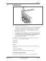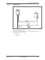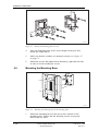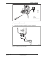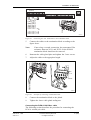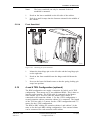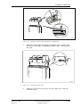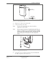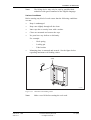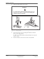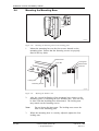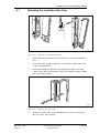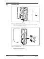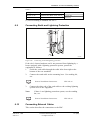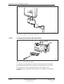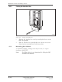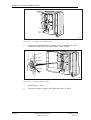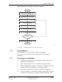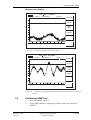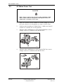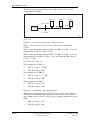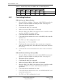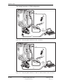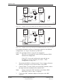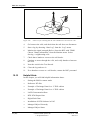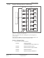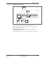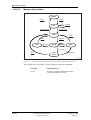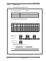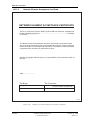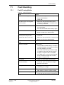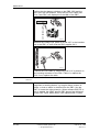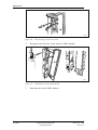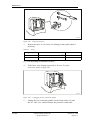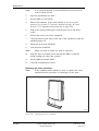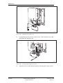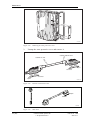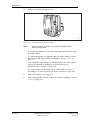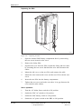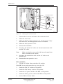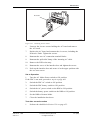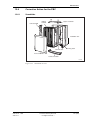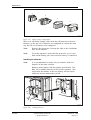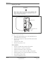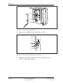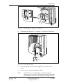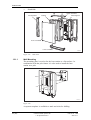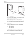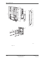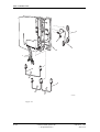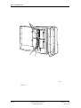
1
P006185A Ericsson GSM System RBS 2302 User’s Guide LZN 302 74 R6B BINDER LABEL Uppgjord (även faktaansvarig om annan) - Prepared (also subject responsible if other) ERA/LRN/ZP Per Olof Höglund Dokansv/Godkänd - Doc respons/Approved 1/001 59-LZN 302 74 Uen Kontr - Checked ERA/LRN/ZPC (Sture Blom) Datum - Date 2000-10-03 Ericsson GSM System HEADING XXX 1 (1) Nr - No. Rev File C Fontsize 10 RBS 2302 Module 98 65 User’s Guide LZB xxx xxx R-state LZN 302 74/C3 R6B Cutting mark 28 38 47 54 H:\SGML_docs\P_arbeten\Martin\1_0059LZN30274R6B.doc Fontsize 12 Fontsize 10 Introduction 1 Safety Instructions 2 Tools and Instruments 3 Site Planning and Requirements 4 Installation of RBS 2302 5 Installation of Power and Battery Cabinet 6 Antenna System Tests 7 Site Installation Tests 8 Optional Tests 9 CAPTION LIST Document No. 001 53-LZN 302 74 RBS 2302 User’s Guide Date Rev 00-10-03 B RBS Site Integration 10 Fault Handling 11 Maintenance 12 Product Data 13 Glossary 14 Spare Parts Catalogue 15 E User’s Guide RBS 2302 User’s Guide RBS 2302 © Ericsson Radio Systems AB — All Rights Reserved — LZN 302 74 2000-11-17 R6B © Ericsson Radio Systems AB — All Rights Reserved — 1 (488) User’s Guide RBS 2302 Due to continued progress in methodology, design and manufacturing, the contents of this document are subject to revision without notice. 2 (488) © Ericsson Radio Systems AB — All Rights Reserved — LZN 302 74 R6B 2000-11-17 User’s Guide RBS 2302 Contents 1 Introduction ................................................................................................... 17 1.1 Target Group ........................................................................................... 18 1.2 Radio Site Implementation Process........................................................ 19 1.3 The Mobile Telephone System Overview ............................................... 22 1.3.1 Switching System (SS).........................................................................22 1.3.2 Base Station System (BSS) ................................................................. 23 1.3.3 Operation and Support System (OSS).................................................24 1.4 Release History ....................................................................................... 24 1.4.1 R2A to R3A...........................................................................................24 1.4.2 R3A to R4A...........................................................................................25 1.4.3 R4A to R5A...........................................................................................27 1.4.4 R5A to R6A...........................................................................................29 1.4.5 R6A to R6B...........................................................................................30 2 Safety Instructions........................................................................................33 2.1 Warnings..................................................................................................33 2.2 Notes........................................................................................................34 2.3 Electrical Hazards....................................................................................35 2.3.1 Electrostatic Discharge, ESD ............................................................... 37 2.4 Working at Heights .................................................................................. 38 2.4.1 Rules and Advice for the Safe Use of Ladders ................................... 38 2.5 Radio Frequency Radiation.....................................................................40 2.6 Other Hazards ......................................................................................... 40 3 Tools and Instruments ................................................................................43 3.1 Tools for Installation of RBS 2302 .......................................................... 43 3.1.1 Installation Tools...................................................................................43 3.1.2 Accessories...........................................................................................44 3.2 Tools for Installation of Power and Battery Cabinet .............................. 44 3.3 Instruments for Antenna System Tests...................................................44 3.4 Instruments for Site Installation Tests.....................................................44 3.5 Tools for Maintenance.............................................................................46 LZN 302 74 2000-11-17 R6B © Ericsson Radio Systems AB — All Rights Reserved — 3 (488) User’s Guide RBS 2302 3.6 Kit specification........................................................................................47 4 Site Planning and Requirements.................................................................49 4.1 Competence requirement........................................................................ 49 4.2 Preconditions........................................................................................... 49 4.2.1 Documents............................................................................................49 4.2.2 Tools and Instruments..........................................................................49 4.3 Ericsson Product and Document Numbering System.............................49 4.3.1 Site Identity...........................................................................................51 4.3.2 Site Documentation .............................................................................. 51 4.4 Installation Planning Overview ................................................................ 51 4.4.1 Basic Information..................................................................................52 4.4.2 Proposed Network Design....................................................................53 4.5 Site Investigation ..................................................................................... 53 4.5.1 Preparations..........................................................................................53 4.5.2 Site Visits..............................................................................................54 4.5.3 Site Investigation Report ...................................................................... 54 4.5.4 Site Preparation....................................................................................55 4.6 Installation Engineering ........................................................................... 55 4.6.1 Cabinet Material Listing........................................................................55 4.6.2 Installation Material...............................................................................56 4.6.3 Site Preparation....................................................................................56 4.6.4 Site Installation Documentation............................................................56 4.6.5 Site Design Documentation..................................................................57 4.7 Site Requirements ................................................................................... 57 4.7.1 Permits..................................................................................................58 4.8 Earthing and Lightning Protection........................................................... 59 4.9 RBS 2302 Overview................................................................................ 59 4.9.1 Base Station RBS 2302........................................................................59 4.9.2 Power and Battery Cabinet PBC..........................................................60 4.10 Configurations........................................................................................61 5 Installation of RBS 2302..............................................................................65 4 (488) © Ericsson Radio Systems AB — All Rights Reserved — LZN 302 74 R6B 2000-11-17 User’s Guide RBS 2302 5.1 Competence requirement........................................................................ 65 5.2 Preconditions........................................................................................... 65 5.2.1 Preconditions for wall-mounted RBS 2302 .......................................... 66 5.2.2 Preconditions for pole-mounted RBS 2302..........................................66 5.2.3 Documents............................................................................................66 5.2.4 Tools and Instruments..........................................................................66 5.3 Overview..................................................................................................67 5.4 Unpacking................................................................................................67 5.5 Mounting the Mounting Plate...................................................................70 5.5.1 Mounting the Mounting Plate on a Wall...............................................70 5.5.2 Mounting the Mounting Plate on a Pole...............................................72 5.6 Mounting the Mounting Base...................................................................74 5.7 Mounting the Installation Box Door ......................................................... 75 5.8 Installation Box ........................................................................................ 77 5.9 Connecting Earth and Lightning Protection.............................................79 5.10 Connecting External Cables..................................................................80 5.10.1 Opening the Interface Box..................................................................80 5.10.2 Connecting the AC Mains...................................................................81 5.10.3 Loosening the Interface Box Gland Plate .......................................... 84 5.10.4 Assembling and Earthing of a twisted pair cable...............................84 5.10.5 Connecting the PCM cable.................................................................88 5.10.6 HDSL transmission module Installation (optional) ............................. 97 5.10.7 Connecting the External– and PBC Alarm Cables ............................ 102 5.10.8 Connecting the Extended OMT cable (optional)................................102 5.10.9 Closing the Interface Box................................................................... 103 5.11 Mounting the Power Supply Adapter (Optional)....................................104 5.12 Mounting the Cabinet ............................................................................ 104 5.13 Connecting Internal Cables ................................................................... 107 5.14 Mounting the Sector Antenna (optional)................................................110 5.15 Mounting the Omnidirectional Antenna (optional).................................111 5.16 Mounting the Multicasting Box (optional) .............................................. 112 LZN 302 74 2000-11-17 R6B © Ericsson Radio Systems AB — All Rights Reserved — 5 (488) User’s Guide RBS 2302 5.17 Connecting the External Antenna Jumpers to the RBS (optional) ....... 114 5.18 Mounting the Sunshields....................................................................... 116 5.18.1 Upper Sunshield ................................................................................. 117 5.18.2 Left Sunshield.....................................................................................118 5.18.3 Lower Sunshield ................................................................................. 118 5.18.4 Front Sunshield...................................................................................119 5.19 4 and 6 TRX Configuration (optional) ................................................... 119 5.20 Mounting the Fan Unit (optional)...........................................................121 5.21 Before leaving the site...........................................................................129 5.22 Appendix, Lifting Device........................................................................129 5.22.1 General............................................................................................... 130 5.22.2 Handling the Lifting Device.................................................................132 6 Installation of Power and Battery Cabinet ................................................. 139 6.1 Competence requirement........................................................................ 139 6.2 Preconditions........................................................................................... 139 6.2.1 Preconditions for wall-mounted PBC....................................................140 6.2.2 Preconditions for pole-mounted PBC...................................................140 6.2.3 Documents............................................................................................140 6.2.4 Tools and Instruments..........................................................................140 6.3 Overview..................................................................................................141 6.4 Unpacking................................................................................................142 6.5 Mounting the Mounting Plate...................................................................143 6.5.1 Mounting the Mounting Plate on a Wall...............................................144 6.5.2 Mounting the Mounting Plate on a Pole...............................................145 6.6 Mounting the Mounting Base...................................................................148 6.7 Mounting the Installation Box Door ......................................................... 149 6.8 Installation Box ........................................................................................ 150 6.9 Connecting Earth and Lightning Protection.............................................151 6.10 Connecting External Cables..................................................................151 6.10.1 Opening the Interface Box..................................................................152 6.10.2 Connection the AC Mains...................................................................154 6 (488) © Ericsson Radio Systems AB — All Rights Reserved — LZN 302 74 R6B 2000-11-17 User’s Guide RBS 2302 6.10.3 Loosening the Interface Box Gland Plate .......................................... 156 6.10.4 Assembling the Cable Gland..............................................................157 6.10.5 Connecting the 24 V DC Power Supply Adapter...............................158 6.10.6 Connecting the Alarm cable ..............................................................159 6.10.7 Closing the Interface Box................................................................... 160 6.11 Mounting the Cabinet ............................................................................ 160 6.12 Connecting Internal Cables ................................................................... 163 6.13 Installing the Batteries ........................................................................... 164 6.14 Mounting the Sunshields....................................................................... 171 6.14.1 Upper Sunshield ................................................................................. 171 6.14.2 Left Sunshield.....................................................................................172 6.14.3 Lower Sunshield ................................................................................. 172 6.14.4 Front Sunshield...................................................................................173 6.15 Before leaving the site...........................................................................173 7 Antenna System Tests ................................................................................. 175 7.1 About these tests.....................................................................................175 7.2 Preconditions........................................................................................... 177 7.3 Checking the Installation ......................................................................... 177 7.4 Calibrating the Antenna Tester................................................................178 7.4.1 Select the Frequency Range................................................................178 7.4.2 Perform a Calibration............................................................................178 7.5 Choosing SWR Test Setup ..................................................................... 179 7.5.1 SWR Test Setup for RBS 2302 passive Antenna Systems.................180 7.6 Performing SWR Test..............................................................................181 7.7 Choosing DTF Test Setup.......................................................................183 7.7.1 DTF Test Setup for RBS 2302 passive Antenna Systems..................184 7.7.2 Entering Cable Parameters.................................................................. 184 7.8 Performing DTF Test...............................................................................186 7.9 Calculating Feeder Attenuation ............................................................... 187 7.9.1 Examples of Feeder Attenuation calculations......................................188 7.10 Test Record........................................................................................... 189 LZN 302 74 2000-11-17 R6B © Ericsson Radio Systems AB — All Rights Reserved — 7 (488) User’s Guide RBS 2302 7.10.1 Test Record Supplement....................................................................190 8 Site Installation Tests...................................................................................191 8.1 Preface.....................................................................................................191 8.1.1 About These Tests ............................................................................... 191 8.1.2 Testing Procedure ................................................................................ 191 8.2 Preconditions........................................................................................... 191 8.2.1 Previous Records ................................................................................. 191 8.2.2 Software requirements..........................................................................191 8.2.3 Removal of Conducting Material .......................................................... 192 8.3 Radio Cabinet RBS 2302 ........................................................................ 192 8.3.1 Introduction........................................................................................... 192 8.3.2 Location of the RBS User Interface ..................................................... 192 8.3.3 Optical Indicators..................................................................................193 8.3.4 Switches and Connectors.....................................................................196 8.3.5 Power Switches in the RBS ................................................................. 196 8.4 Power and Battery Cabinet(Optional)......................................................197 8.4.1 Introduction........................................................................................... 197 8.4.2 Location of the PBC Control Panel...................................................... 197 8.4.3 Control panel ........................................................................................ 198 8.4.4 Power Switches in the PBC ................................................................ 200 8.5 Start-up and Shut-down...........................................................................201 8.5.1 Start-up and shut-down of the RBS..................................................... 201 8.5.2 Start-up and shut-down of the RBS and PBC ..................................... 202 8.6 Alarms and Commands...........................................................................203 8.6.1 Introduction........................................................................................... 203 8.6.2 Power and Battery Cabinet (PBC) ....................................................... 203 8.7 Connecting the OMT ............................................................................... 205 8.8 Test Sequence.........................................................................................206 8.8.1 Preparations..........................................................................................206 8.8.2 Flowchart .............................................................................................. 207 8.9 AC Mains Power Test..............................................................................208 8 (488) © Ericsson Radio Systems AB — All Rights Reserved — LZN 302 74 R6B 2000-11-17 User’s Guide RBS 2302 8.10 Fan Unit Test.........................................................................................209 8.11 Check IDB..............................................................................................210 8.11.1 OMT related actions. Overview..........................................................211 8.11.2 Read IDB ............................................................................................ 211 8.11.3 Create IDB..........................................................................................211 8.11.4 Define External Alarms for R6............................................................213 8.11.5 Define External Alarms for R7............................................................213 8.11.6 Define External Alarm: Fan Unit for R6 and R7................................214 8.11.7 Define External Alarm: HDSL for R6 and R7 .................................... 215 8.12 Define Tei .............................................................................................. 215 8.13 Define PCM Parameters (E1, 120 ohm) ............................................... 216 8.14 Define PCM Parameters (T1, 100 ohm) ............................................... 216 8.14.1 Defining Short Haul parameters.........................................................217 8.14.2 Defining Long Haul parameters..........................................................219 8.15 HDSL Configuration...............................................................................225 8.15.1 Link configuration................................................................................225 8.15.2 LED Indicators .................................................................................... 226 8.15.3 Strapping.............................................................................................227 8.15.4 Test of HDSL......................................................................................229 8.15.5 Start-up............................................................................................... 229 8.16 Install IDB .............................................................................................. 229 8.17 Fault Status Reading.............................................................................230 8.18 External Alarm Tests ............................................................................. 231 8.18.1 External Alarm Test, 2 TRX Configuration.........................................232 8.18.2 External alarm test on RBS 1, 4 TRX and 6 TRX Configurations.....232 8.18.3 External alarm test on RBS 2, 4 TRX and 6 TRX Configurations.....232 8.18.4 External alarm test on RBS 3, 4 TRX and 6 TRX Configurations.....232 8.19 Battery Backup Test, RBS with Internal Battery ................................... 233 8.19.1 Test Procedure ................................................................................... 233 8.20 Battery Backup Test, RBS with External Battery (PBC).......................233 8.20.1 Switch Settings, Before and After Test .............................................. 234 LZN 302 74 2000-11-17 R6B © Ericsson Radio Systems AB — All Rights Reserved — 9 (488) User’s Guide RBS 2302 8.20.2 Test Procedure, 2 TRX Sector Configuration .................................... 234 8.20.3 Test Procedure, 4 TRX and 6 TRX Configurations ........................... 234 8.21 Concluding Routines..............................................................................236 8.22 Test Record........................................................................................... 237 8.22.1 Site Data.............................................................................................238 8.22.2 Test Result..........................................................................................239 8.22.3 Trouble Report....................................................................................240 8.22.4 Repair Delivery Note ‘‘Blue Tag’’ ....................................................... 240 9 Optional Tests...............................................................................................241 9.1 Preconditions........................................................................................... 241 9.1.1 Previous Tests......................................................................................241 9.1.2 Tester qualifications..............................................................................241 9.1.3 Electrostatic Discharge.........................................................................241 9.2 MS Call Test using BSC Simulator......................................................... 242 9.2.1 Test Parameters................................................................................... 242 9.2.2 Cables...................................................................................................243 9.2.3 Test using the MS and BSC Simulator................................................ 243 9.2.4 Test through HDSL using the MS and BSC Simulator .......................246 9.2.5 Test Record.......................................................................................... 252 10 RBS Site Integration...................................................................................253 10.1 Introduction............................................................................................ 253 10.1.1 Overview.............................................................................................253 10.1.2 Range of Test.....................................................................................253 10.1.3 Flowchart ............................................................................................ 255 10.2 Preconditions......................................................................................... 256 10.2.1 Preconditions for the BSC..................................................................256 10.2.2 Preconditions for the RBS..................................................................256 10.3 Transmission Test ................................................................................. 256 10.3.1 Transmission Test E1.........................................................................256 10.3.2 Transmission Test T1.........................................................................257 10.3.3 Transmission Test E1 with HDSL ...................................................... 257 10 (488) © Ericsson Radio Systems AB — All Rights Reserved — LZN 302 74 R6B 2000-11-17 User’s Guide RBS 2302 10.4 Preparations...........................................................................................257 10.4.1 Check of Data.....................................................................................257 10.4.2 Check the BTS Software....................................................................259 10.4.3 Check the Abis Paths.........................................................................260 10.4.4 Check the Digital Path........................................................................260 10.5 Connecting the RBS from the BSC.......................................................260 10.5.1 Bring MO’s into Service and Deblock ................................................ 260 10.5.2 Activation of BTS PCM Supervision (Optional)..................................264 10.5.3 Verification of Downloaded RBS Software.........................................265 10.5.4 Activation and Check of Cell.............................................................. 265 10.5.5 Agree upon Parameters ..................................................................... 266 10.6 Call Tests on Air Interface.....................................................................266 10.6.1 Call Tests using TEMS.......................................................................266 10.6.2 Diversity Call Test ............................................................................. 267 10.6.3 Call Test to MS from fixed Network................................................... 273 10.7 Test of External Alarms.........................................................................273 10.8 Leaving Site Routines............................................................................274 10.9 Handover Test ....................................................................................... 275 10.10 Helpful Hints ........................................................................................ 276 10.10.1 Setting the RBS in remote mode ..................................................... 277 10.10.2 Reference DT-files............................................................................277 10.10.3 Example of Exchange data for a 2-TRX cabinets............................278 10.10.4 Example of Exchange data for a 6-TRX cabinet ............................. 281 10.10.5 LAPD Concentration Data................................................................ 283 10.10.6 BTS PCM Supervision .....................................................................283 10.10.7 Digital Path Data...............................................................................283 10.10.8 Installation of BTS Software in IOG................................................. 283 10.10.9 Managed Object Hierarchy...............................................................285 10.10.10 Managed Object States..................................................................286 10.11 Test Records ....................................................................................... 287 10.11.1 Network Element Integration Test....................................................287 LZN 302 74 2000-11-17 R6B © Ericsson Radio Systems AB — All Rights Reserved — 11 (488) User’s Guide RBS 2302 10.11.2 Network Element Acceptance Certificate.........................................288 11 Fault Handling.............................................................................................289 11.1 Fault Tracing Hints ................................................................................ 289 11.2 Fault Code List ...................................................................................... 290 11.2.1 Terminology ........................................................................................ 290 11.2.2 Decoding of Fault Maps ..................................................................... 291 11.2.3 SO Fault Lists.....................................................................................293 11.2.4 AO Fault Lists.....................................................................................300 11.3 Trouble Report.......................................................................................305 12 Maintenance.................................................................................................309 12.1 Maintenance Process Overview............................................................309 12.1.1 How to use this chapter......................................................................309 12.1.2 General............................................................................................... 310 12.1.3 Fault Handling Workflow.....................................................................310 12.1.4 Fault Analysis from OMC ................................................................... 311 12.1.5 RBS 2302 Maintenance Process ....................................................... 313 12.1.6 Fault Cases and External Alarms.......................................................314 12.2 Maintenance General for RBS 2302 ..................................................... 315 12.2.1 Introduction......................................................................................... 315 12.2.2 Location of the RBS User Interface ................................................... 315 12.2.3 Optical Indicators................................................................................316 12.2.4 Switches and Connectors...................................................................318 12.2.5 Changing the RBS Local/Remote Mode............................................ 319 12.2.6 Shut down Sequence ......................................................................... 320 12.2.7 Start up Sequence..............................................................................323 12.2.8 Tightening Torques for RBS 2302......................................................325 12.2.9 Cable connections overview for RBS 2302........................................325 12.3 Maintenance General for the PBC........................................................ 326 12.3.1 Introduction......................................................................................... 326 12.3.2 Location of the PBC User Interface ................................................... 326 12.3.3 Control Panel......................................................................................327 12 (488) © Ericsson Radio Systems AB — All Rights Reserved — LZN 302 74 R6B 2000-11-17 User’s Guide RBS 2302 12.3.4 Supervision of the PBC ...................................................................... 329 12.3.5 PBC originated Alarms to the RBS .................................................... 329 12.3.6 Stand Alone Mode..............................................................................330 12.3.7 Fault Codes ........................................................................................ 330 12.3.8 Commands..........................................................................................331 12.3.9 Shut down Sequence ......................................................................... 331 12.3.10 Start up Sequence............................................................................334 12.3.11 Tightening Torques for the PBC.......................................................336 12.3.12 Cable connections overview for the PBC.........................................337 12.4 Fault Localization...................................................................................337 12.4.1 Fault Tracing Guidelines for RBS 2302 ............................................. 338 12.4.2 Fault Tracing Guidelines for the PBC ................................................ 343 12.5 Corrective Action for the RBS............................................................... 349 12.5.1 HDSL Modem ..................................................................................... 349 12.5.2 Fan Unit (Optional) ............................................................................. 352 12.5.3 Sunshields .......................................................................................... 357 12.5.4 Sector Antenna...................................................................................367 12.5.5 Omnidirectional Antenna .................................................................... 369 12.5.6 External Antenna ................................................................................ 370 12.5.7 Multicasting Box..................................................................................371 12.5.8 Battery.................................................................................................373 12.5.9 Cables.................................................................................................374 12.5.10 Radio Cabinet...................................................................................377 12.5.11 PSA...................................................................................................383 12.5.12 Fuses................................................................................................ 385 12.5.13 Connection Board.............................................................................387 12.5.14 Transmission Board..........................................................................393 12.5.15 AC Board .......................................................................................... 397 12.5.16 Mounting Base..................................................................................402 12.5.17 Internal Synchronization (Calibrate Oscillator).................................407 12.6 Corrective Action for the PBC............................................................... 409 LZN 302 74 2000-11-17 R6B © Ericsson Radio Systems AB — All Rights Reserved — 13 (488) User’s Guide RBS 2302 12.6.1 Sunshields .......................................................................................... 409 12.6.2 Batteries..............................................................................................416 12.6.3 Cables.................................................................................................425 12.6.4 Battery Cabinet...................................................................................427 12.6.5 Fuses .................................................................................................. 435 12.6.6 EMC Board ......................................................................................... 437 12.6.7 DC Surge Board ................................................................................. 440 12.6.8 AC Board ............................................................................................ 443 12.7 Preventive Maintenance for the RBS....................................................446 12.7.1 Sunshields .......................................................................................... 447 12.7.2 Internal Battery ................................................................................... 447 12.7.3 Cooling flanges...................................................................................447 12.7.4 Connection Board...............................................................................448 12.7.5 Transmission Board............................................................................448 12.7.6 AC Board ............................................................................................ 448 12.7.7 Internal Synchronization (optional).....................................................448 12.7.8 Fan Unit (optional)..............................................................................450 12.8 Preventive Maintenance for the PBC....................................................450 12.8.1 Sunshields .......................................................................................... 451 12.8.2 Cooling flanges...................................................................................451 12.8.3 Batteries..............................................................................................451 12.8.4 EMC Board ......................................................................................... 452 12.8.5 DC Surge Board ................................................................................. 452 12.8.6 AC Board ............................................................................................ 452 12.9 Concluding Routines..............................................................................452 12.9.1 Transport of a Faulty Unit...................................................................453 12.9.2 Report of Finished Work.....................................................................453 12.9.3 Repair Delivery Note - “Blue Tag”......................................................453 13 Product Data................................................................................................455 13.1 Radio Base Station RBS 2302..............................................................455 13.1.1 Wall Mounting.....................................................................................456 14 (488) © Ericsson Radio Systems AB — All Rights Reserved — LZN 302 74 R6B 2000-11-17 User’s Guide RBS 2302 13.1.2 Pole Mounting.....................................................................................457 13.1.3 Optional Fan Unit................................................................................457 13.1.4 Optional HDSL transmission module ................................................. 458 13.1.5 Lifting Kit (optional).............................................................................458 13.1.6 Dimensions and Weight......................................................................459 13.1.7 Space Requirements.......................................................................... 459 13.1.8 Climatic Endurance.............................................................................461 13.1.9 Vibrations............................................................................................461 13.1.10 Acoustic Noise..................................................................................461 13.1.11 Power Supply....................................................................................461 13.1.12 Battery Backup ................................................................................. 462 13.1.13 Earthing.............................................................................................463 13.1.14 Transmission.....................................................................................463 13.1.15 External Alarms ................................................................................ 464 13.1.16 Antenna Connections ....................................................................... 465 13.2 Power and Battery Cabinet (optional)................................................... 466 13.2.1 Wall Mounting.....................................................................................467 13.2.2 Pole Mounting.....................................................................................468 13.2.3 Dimensions and Weight......................................................................469 13.2.4 Space Requirements.......................................................................... 469 13.2.5 Climatic Endurance.............................................................................470 13.2.6 Vibrations............................................................................................471 13.2.7 Acoustical Noise ................................................................................. 471 13.2.8 Power supply...................................................................................... 471 13.2.9 PBC Backup Capacity........................................................................ 472 13.2.10 Earthing.............................................................................................473 13.3 HDSL Modem ........................................................................................ 473 13.3.1 General............................................................................................... 473 13.3.2 HDSL Modem Technical Specification...............................................473 13.3.3 Material ............................................................................................... 475 14 Glossary.......................................................................................................477 LZN 302 74 2000-11-17 R6B © Ericsson Radio Systems AB — All Rights Reserved — 15 (488) User’s Guide RBS 2302 This page is intentionally left blank 16 (488) © Ericsson Radio Systems AB — All Rights Reserved — LZN 302 74 R6B 2000-11-17 Introduction 1 Introduction P003783A Figure 1 RBS 2302 and PBC, wallmounted • The RBS 2302 is a high quality micro base station which enables a simpler site search process, whilst at the same time, allowing for cost-efficient implementations of high capacity radio networks. This makes the RBS 2302 very landlord friendly and easy to place wherever you need it. • The RBS 2302 can be mounted on a pole, like a lamp post or in an antenna tower, or directly on the wall. In itself, the RBS 2302 is a complete BTS site, including transmission, integrated power supply, optionally integrated antennas and a optional battery-backed power supply. The RBS 2302 User’s Guide consists of the chapters listed below. A brief summary of the chapters is presented. Introduction This chapter. Safety Contains information that shows the system used for presenting safety instructions. Tools and Instruments Contains lists of all recommended tools and instruments. Site Planning and Requirements Describes the installation engineering process for the RBS 2302. LZN 302 74 2000-11-17 R6B © Ericsson Radio Systems AB — All Rights Reserved — 17 (488) Introduction Installation of RBS 2302 Describes activities for the installation of the mounting base, connection of cables, external antenna and mounting the radio cabinet on the mounting base. Installation of Power and Battery Cabinet Describes activities for the installation of the mounting base, connection of cables and mounting the battery cabinet on the mounting base. Antenna System Tests Describes the site specific tests for antennas that can be performed at site. Site Installation Tests Describes the site specific tests that can be performed at site. Optional Tests Describes the optional site specific tests that can be performed at site. RBS Site Integration Describes how to integrate a RBS site into a network. Fault Handling Contains helpful information when an error on site has occured, for instance the total fault code list, fault tracing hints and information regarding trouble reports. Maintenance Describes first line Maintenance which means that swap repair is made at the site and that only replaceable units are handled. Product Data Technical data for all parts that can be located on site. Glossary Contains abbreviations and acronyms used in the text. Spare Parts Catalogue Contains relevant information for ordering first line spare parts. 1.1 Target Group The target group for this binder is all personnel involved in the RBS 2302 activities. 18 (488) © Ericsson Radio Systems AB — All Rights Reserved — LZN 302 74 R6B 2000-11-17 Introduction The aim of the RBS 2302 User’s Guide is to present the information in a userfriendly way. If you have any comments or questions regarding the usability or the contents, please contact your local Ericsson company. Help Desk E-mail address to Product Line Maintenance Base Transceiver Stations helpdesk (for Ericsson internal use only): [email protected] See also http://gsmrbs.ericsson.se/technical_support/ for more information. 1.2 Radio Site Implementation Process Con tract is ed sign Network Planning Acceptance (of site) Radio Site Implementation Process Site Acquisition Civil Works Engineering Installation & Integration P004385A Figure 2 The Radio Site Implementation Process The Installation and Integration process is part of the overall Radio Site Implementation process which covers the work from the beginning stages of getting an order and planning and designing the entire network down to installing the RBS sites and integrating them into the network. For further information about the specific planning process, see chapter Site Planning and Requirements. LZN 302 74 2000-11-17 R6B © Ericsson Radio Systems AB — All Rights Reserved — 19 (488) Introduction Network Planning Process The Network Planning process consists of the following activities: • Dimensioning of network. • Dimensioning of equipment for radio, transmission, switching, operation and maintenance. • Defining and ordering market adaptation products, for example programs for national signalling towards the public telephone network. • Measuring of radio frequency and interference. • Producing digital maps and data. Site Acquisition The Site Acquisition process is performed in close co-operation with the Civil Works process and to some extent with the Engineering process. The Site Acquisition process consists of the following activities: • Searching for sites and gaining a site appraisal. • Outlining the site design and evaluating the cost. • Negotiating and signing leasing contracts. • Handling permits and arranging a hand-over to the Engineering personnel. Civil Works The Civil Works process is performed in close co-operation with the Site Acquisition process and to some extent with the Engineering process The Civil Works process consists of the following activities: • Preparing a detailed civil works design of the site. • Updating the costs for the site construction. • Arranging the site construction. • Performing a site inspection and handing over an as-built document to the Engineering personnel. Engineering The Engineering process begins when the Site Acquisition process and Civil Works process are complete. The Engineering process consists of the following activities: 20 (488) • Measuring and collecting information about the sites. • Designing the antenna and radio configuration and producing cable drawings. • Making drawings showing the position of antenna and RBS equipment. © Ericsson Radio Systems AB — All Rights Reserved — LZN 302 74 R6B 2000-11-17 Introduction • Defining areas of responsibility between the buyer and teh contractor. • Producing site specific information in the Radio Site Installation Documentation. Installation and Integration The work involved in this process is performed by Installation personnel and Test and Integration personnel. Installation personnel are responsible for the following activities: • Installing the RBS on the ground, on a wall. • Earthing the RBS. • Connecting a power supply to the RBS. • Connecting the antenna system to the RBS. • Installing cable ladders and cable ducts. • Installing battery back-up. • Installing PCM cables. The Test and Integration personnel are responsible for the following activities: LZN 302 74 2000-11-17 R6B • Performing the tests specified in the contract and integrating the site. • Troubleshooting if tests indicate a fault. • Documenting the test results in the Radio Site Installation Documentation which is returned to the Engineering personnel. © Ericsson Radio Systems AB — All Rights Reserved — 21 (488) Introduction 1.3 The Mobile Telephone System Overview SS PSTN GMSC Public services Telephone Network AUC ILR HLR EIR DTI MSC/VLR BSS TRC OSS BSC BTS/RBS P005021B Figure 3 GSM System Overview Ericsson’s GSM System is a mobile telephone system containing the frequency bands GSM 900, GSM 1800 and GSM 1900. The GSM network is divided up into three major systems: 1.3.1 • Switching System (SS) • Base Station System (BSS) • Operation and Support System (OSS) Switching System (SS) The Switching System consists of the following elements: Mobile Services Switching Centre (MSC) The MSC performs the telephony switching functions of the system. It controls calls to and from other telephone and data systems and other functions such as network interfacing, common channel signalling. 22 (488) © Ericsson Radio Systems AB — All Rights Reserved — LZN 302 74 R6B 2000-11-17 Introduction Gateway MSC A Gateway is a node to interconnect two networks. The gateway is often implemented in an MSC. Home Location Register (HLR) The HLR is a database used for storage and management of subscriptions including a subscriber’s service profile, location information and activity status. Visitors Location Register (VLR) The VLR is a database containing temporary subscribers information needed by the MSC to service visiting subscribers. The VLR is always integrated with the MSC. When a new mobile station roams into a new MSC area the VLR connected tot he MSC will request data about the mobile station from the HLR. Authentication Centre (AUC) The AUC provides authentication and encryption parameters that verify the user’s identity and ensure the confidentiality of each call. Equipment Identity Register (EIR) The EIR is a database containing information about the mobile equipment identities that prevent calls from stolen, unauthorized or defective mobile stations. Data Transmission Interworking Unit (DTI) The DTI consists of both hardware and software and provides an interface to various networks for data communication. Through the DTI users can alternate between speech and data during the same call. Interworking Location Register (ILR) ILR makes inter—system roaming possible between the AMPS network and the GSM 1900 network . ILR consisit of an AMPS HLR and partsof a GSM 1900 VLR. 1.3.2 Base Station System (BSS) The Base Station System consists of the following elements: Transcoder Controller (TRC) The TRC provides teh BSS with rate adaptation capabilities. A device which performs rate adaptation is called a transcoder. The bitrate per channel is decreased from 64 kbit/s to 16kbit/s. This saves transmission links between the MSC to the BSCs. Base Station Controller (BSC) The BSC provides all the control functions and physical links between the MSC and the BTS. It is a high capacity switch that handles LZN 302 74 2000-11-17 R6B © Ericsson Radio Systems AB — All Rights Reserved — 23 (488) Introduction functions such as: handover, cell configuration data, and control of radio frequency power levels in base transceiver stations. A number of BSCs are served by an MSC. Base Transceiver Station (BTS) The BTS handles the radio interface to the mobile station. The BTS is the radio equipment (transceivers and antennas) needed to serve each cell in the network. A group of BTSs are controlled by a BSC. The Radio Base Station (RBS) includes all the radio and transmission interface equipment needed on one site. 1.3.3 Operation and Support System (OSS) The Operation and Support System (OSS) is the functional entity from which the network operator monitos and controls the system. It is a two-level management function with a Network management Centre (NMC) and subordinate Operation and Maintenance Centres (OMC). NMC staff concentrate on system-wide issues whereas local personnel at each OMC concentrate on short-term regional issues. The OSS is designed to provide a Management system which supports a number of other network elements, the MSC, BSC, BTS, VLR, HLR, EIR, AUC and Mobile Intelligent Network Nodes (IN). 1.4 Release History Except editorial changes such as correction of spelling, grammar and layout, this manual has been revised as follows: 1.4.1 R2A to R3A The following information of major importance has been added to the binder sections listed below: Site Planning and Product Data • Block Diagram of PBC updated. • Chapter Transmission updated. Installation of Power and Battery Cabinet • Dimension sketch included, showing the mounting plate and position of the mounted equipment. Installation of RBS 2302 24 (488) • Optional HDSL modem. • 4 TRX and 6 TRX configurations. • Optional Fan Unit. • Dimension sketch included, showing the mounting plate and position of the mounted equipment. © Ericsson Radio Systems AB — All Rights Reserved — LZN 302 74 R6B 2000-11-17 Introduction Site Installation Tests • New chapter Handover Test. • 4 TRX and 6 TRX configurations. • Optional HDSL modem. Maintenance Manual • New chapter HDSL Modem. • New chapter Fan Unit. General Information • Fault Code List updated. Spare Parts Catalogue 1.4.2 • Optional Fan Unit. • Optional HDSL modem. R3A to R4A In this release of RBS 2302 User’s Guide the binder has been given consecutive page numbers. Also a major structural change has been done. These changes, and other information of major importance that has been added, are listed below: Introduction • Section Mobile Telephony Overview has been updated and moved here from chapter Site Planning and Product Data (new name for this chapter in R4A, see below). • Section Radio Site Implementation Process has been added. Tools and Instruments The chapter Tools and Instruments has been updated. Site Planning and Requirements The chapter formerly called Site Planning and Product Datahas been divided into two separate chapters; Site Planning and Requirements and Product Data. • Site Planning and Requirements now only contains information about site specific requirements. Installation of RBS 2302 • LZN 302 74 2000-11-17 R6B Parts of the subsection HDSL Transmission Module Installation have been moved here from the chapter formerly called General Information. © Ericsson Radio Systems AB — All Rights Reserved — 25 (488) Introduction Antenna System Tests This chapter has been extracted from chapter Site Installation Tests. • Subsection Anritsu SiteMaster has been updated. Site Installation Tests • In section RBS 2302 the subsections Optical Indicators and Switches and Connectors have been updated. Also the subsection Power Switches in the RBS has been moved here from section Test Sequence. • In section Power and Battery Cabinet the subsection Power Switches in the PBC has been moved here from section Test Sequence. • Section Antenna Installation Tests has been moved to a separate chapter; Antenna System Tests. • In section Test Sequence there have been structural changes. • In section Test Sequence the subsection Flowchart has been updated. • In section Test Sequence two new subsections have been included; AC Mains Power Test and Fan Unit Test. • In section Test Sequence the subsection MS Test Call Using BSC Simulator has been moved to the new chapter Optional Tests. • The section Fault Tracing Hints has been moved to the new chapter Fault Handling. Optional Tests This chapter has been added in R4A. • The subsection MS Test Call Using BSC Simulatorhas been moved here from chapter Site Installation Tests. Fault Handling This chapter has been added in R4A. • The section Fault Tracing Hints has been moved here from chapter Site Installation Tests. • The sections Fault Code List and Trouble Report have been moved here from the chapter formerly called General Information. Maintenance This chapter has been structurally redesigned. Previous section Maintenace General has been divided into two separate sections; Maintenace General for RBS 2302 and Maintenace General for PBC. • 26 (488) In section Maintenace General for RBS 2302the subsections Optical Indicators and Switches and Connectors have been updated. © Ericsson Radio Systems AB — All Rights Reserved — LZN 302 74 R6B 2000-11-17 Introduction Product Data This chapter has been extracted from the chapter formerly called Site Planning and Product Data. It contains the technical data for the different units that can be mounted on site. • Section Lifting Device and parts of section HDSL Modem have been moved here from the chapter formerly called General Information. General information This chapter no longer exists. The information in this chapter has been placed according to the description above. 1.4.3 R4A to R5A Introduction • Information about the new chapter RBS Site Integration added. • Address to helpdesk updated. • Release History updated. Safety The chapter Safety has been updated. Tools and Instruments The chapter Tools and Instruments has been updated. Site Planning and Requirements • The section RBS 2302 Overview has been moved here from chapter Product Data. Installation of RBS 2302 LZN 302 74 2000-11-17 R6B • Information regarding the use of ESD wrist strap added. • Instructions on how to use the drilling template added. • Instructions on how to mount the HDSL door added. Also the information on how to connect the HDSL modem to the PCM connectors has been moved here from chapter Product Data. • Instructions on how to install the fuses with the fuseholder added. • Instructions on how to mount the Power Supply Adapter (PSA) added. • Information on how to connect cabinets when cascade connection is used added. • Section Mounting the Multicasting Box (optional)has been clarified. • Section Connecting the External Antenna Jumpers (optional) has been updated. © Ericsson Radio Systems AB — All Rights Reserved — 27 (488) Introduction • Section Mounting the Sunshields, subsection Upper Sunshield has been given new information. • Section 4 and 6 TRX Configuration (optional) has been updated. • New information on how to route the alarm cable in section Mounting the Fan Unit added. • Section Lifting Device has been moved here, and placed as an appendix, from chapter Product Data. Installation of Power and Battery Cabinet • Information regarding the use of ESD wrist strap added. • Instructions on how to use the drilling template added. • Structural changes in section Connecting External Cables. Antenna System Tests • Subsection Anritsu Site Master has been updated (minor changes). Site Installation Tests • Information regarding the use of ESD wrist strap added. • In section Test Sequence there have been structural changes. • In section Test Sequence the subsection Flowchart has been updated. • In section Test Sequence the subsection formerly called Multidrop has changed name to Network Configuration. Also the information has been updated. • In section Test Sequence the subsection formerly called LBO Parameter Settings (T1) has been divided into to subsections: Define PCM Parameters (E1 120 ) and Define PCM Parameters (T1 100 ). Also the information has been updated. • In section Test Sequence the subsection Network Integration Test has been updated and moved to the new chapter RBS Site Integration. • In section Test Sequence the subsection Handover Test has been updated and moved to the new chapter RBS Site Integration. • In section Test Sequence the subsection HDSL Configuration has been updated and moved here from chapter Installation of RBS 2302. Optional Tests 28 (488) • Information regarding the use of ESD wrist strap added. • The subsection Test through HDSL using the MS and BSC Simulator has been added. © Ericsson Radio Systems AB — All Rights Reserved — LZN 302 74 R6B 2000-11-17 Introduction RBS Site Integration This chapter has been added in R5A. Fault Handling No changes. Maintenance • In section Fault Localization, information added to the subsections Fault tracing Guidelines for RBS 2302and Fault tracing Guidelines for the PBC. • Information about the fuses for the Fan Unit added to section Corrective Action for the RBS, subsection Fan Unit (optional). • Information that the RBS do not have to be removed from service when changing the front, lower, left or upper sunshield added to section Corrective Action for the RBS, subsection Sunshields. • Instructions on how to install the fuses with the fuseholder added to section Corrective Action for the RBS, subsection Fuses. • New instructions regarding the fuseholder added to section Corrective Action for the RBS, subsection Connection Board. • The Blue Tag, including the instructions, has been updated in section Concluding Routines. Product Data 1.4.4 • The section RBS 2302 Overview has been moved to chapter Site Planning and Requirements. • In section Radio Base Station RBS 2302, subsection Power Supply the values for Heat Generation have been changed. • In section Power and Battery Cabinet (optional), subsection Climatic Endurance the temperature range for Normal Condition has been changed. • Section Lifting Device has been moved to chapter Installation of RBS 2302. R5A to R6A Introduction Release History updated. Tools and Instruments The chapter Tools and Instruments has been updated. Installation of RBS 2302 • LZN 302 74 2000-11-17 R6B Information added that it may be necessary to protect the cabinet during installation due to bad weather conditions. © Ericsson Radio Systems AB — All Rights Reserved — 29 (488) Introduction • New section added, Assembling and earthing of a twisted pair cable. • New section added, Connecting the PCM cable. This section contains new information how to connect the PCM cable with DC isolation. • The product number for the 75 coaxial cable with DC isolation has been changed to RPM 518 974/2. • Information regarding the hysteresis of the temperature sensors for the fans added. Installation of Power and Battery Cabinet Information added that it may be necessary to protect the cabinet during installation due to bad weather conditions. Site Installation Tests • Information regarding SW requirements added in section Preface. • The test section now contains only the tests. General information necessary to perform the tests has been moved to earlier sections. Example of this are sections Start-up and Shut-down and Connecting the OMT. • Other minor structural changes have also been made. • The flowchart in section Test Sequence has been updated. • Information regarding the hysteresis of the temperature sensors for the fans added in section Fan Unit Test. • In section HDSL Configuration the function of the leds has been updated. • In section Test Record the test record for Stand Alone Tests has been updated. Maintenance In section Preventive Maintenance for the RBS the subsection Internal Synchronization has been updated. 1.4.5 R6A to R6B General Cable gland capacity has been changed throughout the document from 8–19 mm to 7–15 mm. Product number of wrist strap has been removed throughout the manual. “DC/Alarm” cable has been replaced by “DC/Data cable” throughout the manual. Introduction Release History updated. 30 (488) © Ericsson Radio Systems AB — All Rights Reserved — LZN 302 74 R6B 2000-11-17 Introduction Tools and Instruments The chapter Tools and Instruments has been updated. Antenna System Tests The entire chapter Antenna System Tests has been updated due to new version of Site Master. Site Installation Tests • New order for test sequence. • New instruction for installation of IDB. RBS Site Integration In section Helpful Hints, a section added containing an example of exchange data for 6 TRX. Product Data LZN 302 74 2000-11-17 R6B • In section Radio Base Station RBS 2302, subsection Power Supply, the information regarding the power supply and heat generation has been updated. • In section Power and Battery Cabinet, subsection Power Supply, the information regarding the power supply and heat generation has been updated. • In section Radio Base Station RBS 2302, subsection Vibrations, information regarding base station vibration withstanding has been changed. © Ericsson Radio Systems AB — All Rights Reserved — 31 (488) Introduction This page is intentionally left blank 32 (488) © Ericsson Radio Systems AB — All Rights Reserved — LZN 302 74 R6B 2000-11-17 Safety Instructions 2 Safety Instructions This chapter shows the system used for presenting safety information. Note: Reduce the risk of accidents by studying all the instructions carefully before starting work. If questions arise regarding the safety instructions, contact the supervisor or the local Ericsson company. Where local regulations exist, these are to be followed. The safety information in this manual is a supplement to local regulations. It is the responsibility of the local project manager to make certain that local regulations are known and followed. The relevant manual (including this safety information) and specific instructions supplied by Ericsson must be followed in any work performed on the Ericsson products or systems. A sufficient knowledge of English or of any of the other languages in which the manuals or instructions are printed is necessary. The safety information in the relevant manuals presupposes that any person performing work on Ericsson products or systems has the necessary education, training and competence required in order to perform that work correctly. For certain work, additional training or special training may be required. For more precise information on the amount and content of the general and/or special training required for work on Ericsson products or systems, please contact the supervisor or the local Ericsson company. 2.1 Warnings Warnings are used to indicate hazardous activities. The warnings are preceded by the common hazard symbol. P002643 Figure 4 Hazard symbol The following three warning levels, shown here in order of urgency, are used: DANGER Danger means that an accident may occur if the safety precautions are neglected. This type of accident is likely to be fatal. LZN 302 74 2000-11-17 R6B © Ericsson Radio Systems AB — All Rights Reserved — 33 (488) Safety Instructions WARNING Warning means that an accident may occur if the safety precautions are neglected. This type of accident may be fatal or cause serious injury. It may also damage the product. CAUTION Caution means that an accident may occur if the safety precautions are neglected. This type of accident may cause injury or damage the product. The following special symbols are used to indicate the risk of radio frequency radiation, electrical hazards and electrostatic discharge: P002644A Figure 5 Radio frequency radiation P002645A Figure 6 Electrical hazard P002646A Figure 7 Electrostatic discharge Warnings are used throughout this manual to alert the reader to special instructions concerning a particular task or operation that may be hazardous if performed incorrectly or carelessly. Therefore, read the instructions carefully. Strict compliance with the special instructions while performing a task is the best way of preventing accidents. 2.2 Notes Note: 34 (488) Notes are used to call the reader’s attention to key points that might otherwise be overlooked. © Ericsson Radio Systems AB — All Rights Reserved — LZN 302 74 R6B 2000-11-17 Safety Instructions 2.3 Electrical Hazards High Voltage DANGER High voltage is used in the operation of this equipment. Both direct contact with the mains power and indirect contact via damp items or moisture can be fatal. • The AC installation must be carried out according to local regulations. These regulations may require the work to be carried out by a qualified and authorized electrician. • Remove wrist watches, rings, bracelets, etc. • Switch off the power if the cabinet is damp inside. • Prevent damp entering the equipment during work in bad weather conditions. DANGER Improper electrical installation may cause fire or electrical shock. Approved circuit breakers for the AC mains and the cable’s cross sectional areas must always be selected in accordance with local laws and regulations. Only a qualified and authorized electrician is permitted to install or modify the electrical installation. Cable Markings CAUTION Verify that the cable markings correspond before connecting cables. LZN 302 74 2000-11-17 R6B © Ericsson Radio Systems AB — All Rights Reserved — 35 (488) Safety Instructions Faulty Electric Tools WARNING Do not repair a faulty electric tool yourself. Hand it over to your supervisor in exchange for a functioning tool. Drilling WARNING Do not drill holes in the Radio Base Station. The drill bit may come into contact with live wires. • Always use insulated protective gloves, such as the LYB 1032, when drilling where live wires might be hidden. • Always use eye protectors (goggles) when drilling. Flying chips and dust may get into your eyes. Thunderstorms DANGER Avoid working on electrical installations or towers/masts during thunderstorms. Thunderstorms create strong electric fields. For that reason, and to avoid direct strokes of lightning, it is essential that the equipment is properly earthed for thunderstorm conditions. 36 (488) © Ericsson Radio Systems AB — All Rights Reserved — LZN 302 74 R6B 2000-11-17 Safety Instructions 2.3.1 Electrostatic Discharge, ESD CAUTION Sensitive components such as Integrated Circuits (IC) can be damaged by discharges of static electricity. Electrical charges are generated by friction when a body moves, rubs against clothes, slides against a chair, when shoes rub against the floor, and when you handle ordinary plastics, etc. Such charges may remain for a considerable period of time. Handling of printed board assemblies and IC components Always use an approved antistatic bracelet to avoid damage to components mounted on printed board assemblies. The ESD wrist strap contains a resistor with an ohmic value greater than 1 M in the cable to protect the operator. The resistance value is low enough to discharge the electrostatic voltage. Never replace the cable with any other cable. The ESD wrist strap must be connected to earth. Ericsson recommends wrist strap LYB 250 01/14. Storing and Transporting printed board assemblies and IC Components Use the original packaging. If this is not available, use a conductive material, or a special IC carrier that either short-circuits or insulates all leads of the components. 01_0250A Figure 8 LZN 302 74 2000-11-17 R6B ESD wrist strap LYB 250 01/14 © Ericsson Radio Systems AB — All Rights Reserved — 37 (488) Safety Instructions DANGER To avoid potentially fatal circuits through the body to earth, wrist strap connections must include a resistor of at least 1 M . Test the wrist strap regularly. 2.4 Working at Heights WARNING Some working areas involve the risk of accidents caused by falling objects. For example, when working on a mast, tower or a roof, the following precautions must be taken: 2.4.1 • Personnel working at heights must have the appropriate training and medical certificate. • Full body safety harness and safety helmet must be used. • Adequate protective clothing is essential in cold weather. • All lifting devices must be tested and approved. • During work on a mast, all personnel in the area must wear helmets. Rules and Advice for the Safe Use of Ladders • Make sure that the ladder is undamaged and has been approved for use. • Do not overload the ladder. The following types of ladders must be guyed or otherwise secured 38 (488) • Leaning ladder longer than 5m. • Free-standing ladder with a platform and knee-support, and with over 2 meters height to the platform. • Any other free-standing ladder longer than 3m. © Ericsson Radio Systems AB — All Rights Reserved — LZN 302 74 R6B 2000-11-17 Safety Instructions Positioning the ladder 02_0354A Figure 9 Checking the angle • The ladder’s inclination should be approximately 1:4 (75). Position the ladder according to its gradation indicator (if there is one) or check the angle with your elbow. • Use the ladder foot or a ladder support to reduce the risk of tipping over sideways. • Always attach extension legs to a ladder that is to be used on a sloping base. Never prop up a ladder with boxes, stones or the like. • Extend the ladder completely. • Check that all four anti-slipping treads are firmly positioned on the base. Climbing and using the ladder 01_0354A Figure 10 LZN 302 74 2000-11-17 R6B Climbing the ladder © Ericsson Radio Systems AB — All Rights Reserved — 39 (488) Safety Instructions 2.5 • Climb the ladder facing it. • When you lean sideways, outward from the ladder, your navel should never be outside the edge of the ladder’s frame. • Always keep 3 points of contact (two feet and one hand, two hands one foot) with the ladder when working on it. This will reduce the risk of falling. • Never climb the topmost four rungs of a ladder. If you have to climb up on a roof, the ladder should extend at least one meter above the eaves. Radio Frequency Radiation CAUTION Radio frequency (RF) radiation from antenna systems can endanger your health. Co-ordinate with all mast users to switch off the transmitters when working with, or near, antennas. 2.6 Other Hazards Fire WARNING Fire may spread to neighboring rooms. When working on a radio base station you may have to open cable ducts, channels and access holes, thereby interfering with the fire sectioning of the building. 40 (488) • Close the cable ducts and fire doors (if applicable) as soon as possible. • After completing work on cables, seal the cable ducts according to the regulations for the building. • Minimize the amount of inflammable material. • Avoid storing empty packaging material on the site. • Use a powder or carbon dioxide type of fire extinguisher due to the electric nature of the equipment inside the Radio Base Station. © Ericsson Radio Systems AB — All Rights Reserved — LZN 302 74 R6B 2000-11-17 Safety Instructions Sharp Edges WARNING Wear protective gloves when handling the equipment. There may be sharp metal edges. LZN 302 74 2000-11-17 R6B © Ericsson Radio Systems AB — All Rights Reserved — 41 (488) Safety Instructions This page is intentionally left blank 42 (488) © Ericsson Radio Systems AB — All Rights Reserved — LZN 302 74 R6B 2000-11-17 Tools and Instruments 3 Tools and Instruments This section contains lists of all tools and instruments recommended for complete installation of the RBS 2302 and the Power and Battery Cabinet (PBC). 3.1 Tools for Installation of RBS 2302 The recommended tool set for Installation is Personal Installation Tool Set Product No: LTT 601 96/1. For more information regarding this tool set see: General Installation Instructions 3.1.1 LZN 302 49 Installation Tools The following tools is required from the Personal Installation Tool Set LTT 601 96/1. Description Side cutting pliers Snip nose pliers Wire stripper 0,2-6 mm² Screwdriver, TORX, T10, T20, T30 Screwdriver, wide 3 mm Screwdriver, wide 5.5 mm Adjustable spanner 10″ Penlight, Maglite mini Knife Measuring tape, 5m Voltage tester U-ring wrench 10 mm U-ring wrench 17 mm U-ring wrench 19 mm U-ring wrench 20 mm U-ring wrench 24 mm Torque wrench 4-20 Nm Torque wrench 10-55 Nm Spirit level Socket set 3/8 ″ ESD wrist strap LZN 302 74 2000-11-17 R6B Description Product No: Cordless hammer drill machine tool set 230 V LTT 601 12/2 Cordless hammer drill machine tool set 110 V LTT 601 12/1 © Ericsson Radio Systems AB — All Rights Reserved — 43 (488) Tools and Instruments Crimping Tool Set LTT 601 86 U-ring wrench 15 mm U-ring wrench 18 mm U-ring wrench 22 mm Eye protectors Hearing protector For safety equipment, please refer to chapter Safety. Installation Materials 3.1.2 Description Product No. Sealing Kit 5/NTM 201 230/3 Earthing Set 5/NTM 201 201 Accessories Description Product No. Lifting Device Kit (Lifting Handle SXK 107 5775/1 included) SXK 107 5723/1 Lifting Handle SXK 107 5775/1 The Lifting device may be used for lifting the cabinet up to 5 m and for a weight up to 25 kg. The Power and Battery Cabinet can NOT be lifted equipped with batteries. The handle can be used to carry the cabinets. 3.2 Tools for Installation of Power and Battery Cabinet Same tools as for Section 3.1.1 on page 43. 3.3 Instruments for Antenna System Tests Table 1 3.4 SiteMaster covering GSM 900/1800/1900 one port Antenna test Description Specification Product No. Qty Antenna tester SiteMaster S331B (adapters included) LPK 102 101/5 1 Instruments for Site Installation Tests Different test methods needs various instruments and cabling kits. For example: 44 (488) 1. The Network Integration Test is marked with number 3 in Table 2 on page 45. 2. According to Table 3 on page 45 the test method number 3 requires index C. © Ericsson Radio Systems AB — All Rights Reserved — LZN 302 74 R6B 2000-11-17 Tools and Instruments 3. According to Table 4 on page 46, the index C equals a TEMS kit. This table also gives you information about the product number and required quantity. Information regarding the parts included in the various kits, see Section 3.5 on page 46. Table 2 Explanations for the different test methods Test Method No Explanation 1 Transmission Test 1.5 MBit/s (T1) or 2.0 MBit/s (E1) 2 MS-Call test with BSCSim II 3 Network Integration Test 4 Call Test with BSC connection 5 OMT related tests 6 AC Mains Power Test 7 MS-Call test with BSCSim II through HDSL Table 3 Test method versus required Instruments & accessories Test Method Instruments and Accessories Index A B C D E 2 X 3 X 4 X X X LZN 302 74 2000-11-17 R6B H X X X 6 7 G X 1 5 F X X X © Ericsson Radio Systems AB — All Rights Reserved — X X 45 (488) Tools and Instruments Table 4 Explanations for Instruments & accessories Index Instrument/accessory Product No. Qty A OMT Kit (test set) NTM 201 2159/1 (R6) or NTM 201 2289/1 (R7) 1 Cable, 4-wire to RS 422 connector, 50 m (Extended OMT) RPM 518 976/1 1 Cable, RS 422 connector to RS 232 connector, 2 m (Extended OMT) RPM 518 964/1 1 TEMS GSM Dualband LPB 123 013/2 1 TEMS GSM 1900 LPB 123 014/2 C BSCSim II LPP 106 35/11 1 D Filter Unit (Multi casting box), 2 units are required for 4 TRX, and 3 units is required for 6 TRX configuration. KRF 201 439/1 1-3 E Test Accessories (Call Test), 2 units are required for 4 TRX, and 3 units is required for 6 TRX configuration. NTM 201 2216/3 1-3 F Loop Forward/Backward board LPY 107 757/1 1 G Fluke 79 III Multimeter LPK 102 024/2 1 H MartisDXX HTU-2M ZAT 759 20/101 1 HDSL Cable Kit KDY 196 48/1 1 B Using the OMT SW and TEMS SW A Lap Top PC is needed with following minimum requirements: 3.5 • Intel 486 processor • 66 MHz • 16 MB RAM • MS Windows version 95/NT Tools for Maintenance General Maintenance Tools Depending on the maintenace that is to be performed, use the appropriate tools and instruments from previous sections. Special Maintenance Tools The Loop Forward/backward board CB21, Product No: LPY 107 757/1, is for example used during change of RBS 2302 mounting base or transmission filter board. 46 (488) © Ericsson Radio Systems AB — All Rights Reserved — LZN 302 74 R6B 2000-11-17 Tools and Instruments The cover plate Product No: SXA 117 1926/1 is used to seal the RBS mounting base installation box. It is used if the RBS cabinet is changed and it takes time until the new cabinet is mounted. Item Product no. Loop forward/backward board, CB21 LPY 107 757/1 Cover plate for mounting base SXA 117 1926/1 Instrument for Calibrate Oscillator Product No. LPK 102 102/1 3.6 Pos Description Qty 1 Suitcase 1 2 Instrument Set 1 3 Cable, 1/4 Euro connector jack to 2x BNC plug 1 4 Cable, BNC plug to SMB jack 1 Kit specification Test Accessories Product No. NTM 201 2216/3 (Call Test) List of including parts Item Qty MS cable 3 Adapter 1 Attenuator 30 dB, 2 W 1 BSCSim II Kit Product No. LPP 106 35/nn LZN 302 74 2000-11-17 R6B BSCSim II Kit Product No. BSCSim II Kit LPP 106 35/10 Item Description Qty 1 PC Platform Fieldworks 1 2 BSCSim II Test Tools Software 1 3 BSCSim II User’s guide 1 4 PCM Communication Kit 1 5 Cable Kit for Maxite and RBS 2000 1 6 Cable Kit for Maxite and RBS 2302 1 © Ericsson Radio Systems AB — All Rights Reserved — 47 (488) Tools and Instruments 7 Microsoft Mouse 1 8 Etherlink Card 1 BSCSim II Kit Product No. BSCSim II Kit LPP 106 35/11 Item Description Qty 1 PC Platform Dolch 1 2 BSCSim II Test Tools Software 1 3 BSCSim II User’s guide 1 4 PCM Communication Kit 1 5 Cable Kit for Maxite and RBS 2000 1 6 Cable Kit for Maxite and RBS 2302 1 OMT Kit Product No. NTM 201 2289/1 (R7 Software) Item OMT 32 Bit software OMT Cable (RS 232) OMT User’s Manual OMT Kit Product No. NTM 201 2159/1 (R6 Software) Item OMT 32 Bit software OMT Cable (RS 232) OMT User’s Manual 48 (488) © Ericsson Radio Systems AB — All Rights Reserved — LZN 302 74 R6B 2000-11-17 Site Planning and Requirements 4 Site Planning and Requirements This section describes the installation engineering process. Careful planning of preinstallation activities, such as antennas, cables, power etc. is essential for fast installation and commissioning of base stations. This section contains document rules that are applicable to Ericsson organizations only. 4.1 Competence requirement In order to do site planning work according to this manual in a safe and professional way, the work shall be done by a skilled person. The following qualifications are minimum requirements: 4.2 • Good understanding of radio and telephone engineering. • Good understanding of engineering English. Preconditions The Preconditions section lists general documents needed for installation engineering. 4.2.1 Documents 4.2.2 Ordering Information for RBS 2000 Installation Material 131 62-HRB 105 01/MA Rules and Methods for Installation Engineering EN/LZB 119 2935/6 Standard Site Material Catalogue LZN 302 39 General Installation Instructions LZN 302 49 Tools and Instruments See chapter Tools and Instruments. 4.3 Ericsson Product and Document Numbering System Two concepts or words - product and document - are used at Ericsson. Products are numbered with a product number ("ABC number") which in its basic form consists of a three to five letter combination followed by a digit group of up to seven numbers. This number is called the Product Number. The three-letter group divides products into classes according to use, construction or other essential attributes. The one or two letters for notation of origin are used when the design responsibility does not rest with a Swedish Ericsson company. (Reference document 1120-101 in Standard binder ST1B). LZN 302 74 2000-11-17 R6B © Ericsson Radio Systems AB — All Rights Reserved — 49 (488) Site Planning and Requirements 123/ABCDE 123 4567/12345 R1A Product prefix Class designation Notation of origin Type number Sequence number Suffix R status 01_0067B Figure 11 The complete product identity Documents are numbered using the decimal classification system. A document number consists of a decimal class and the product number of the described product. The decimal class consists of four or five digits that classify the information by activity and subject areas. A decimal class is defined in a decimal class information document that describes which kind of document the decimal class is used for, how the information is used and which document names are permitted. These documents are numbered 0011-XXXX Uen, (XXXX stands for the decimal class which is of interest). Decimal class information documents are filed in the central archives of the company. 12/123 45-123/ABCDE 123 4567/12 Uen A Document prefix Decimal class Product number Language notation Revision status 02_0067B Figure 12 50 (488) The complete document identity © Ericsson Radio Systems AB — All Rights Reserved — LZN 302 74 R6B 2000-11-17 Site Planning and Requirements 4.3.1 Site Identity In installation engineering the whole site is considered to be a product. The site is given a product number from the ABC class IPA (Plants) Example: IPA 110 1001 4.3.2 Site Documentation The build-up of the site is recorded with a number of site documents. The following is a list of suitable decimal classes for the site documents. Decimal class Approved document name Explanation 127 11- Plant specification 127 04- Configurationdata Site data 193 38- Cell design data Cell parameters 153 12- Antenna placement information Antenna and tower arrangement 153 38- Situating plan Site layout 193 05- Floor plan drawing 193 18- Cable distribution diagram 193 20- Cabling information 193 24- Cable way drawing 179 61- Certificate of conformance 152 83- Test report Power supply A document showing the physical layout of the previous site, a situating plan, will be numbered as shown in the example below. Example: 153 38-IPA 110 1001 A base station with integrated antennas will of course not need all the mentioned documentation, whereas a base station with a distributed antenna system might need a more detailed documentation. 4.4 Installation Planning Overview The figure below is an overview of the Installation Planning process. LZN 302 74 2000-11-17 R6B © Ericsson Radio Systems AB — All Rights Reserved — 51 (488) Site Planning and Requirements Proposed network design Cabinet material listing Plant specification 1/127 11-IPA...... Cabinet assembly Site investigation Site investigation report Design review Installation engineering Confirmed system design Plant specification 2/127 11-IPA...... Installation material order Site installation documentation SITE PREPARATION 01_0068B Figure 13 4.4.1 Planning overview Basic Information The necessary information for planning of a site is made up of: 52 (488) • The technical specification in the contract regarding the base station. • Information about the transmission network standard. • Information about the network plan. © Ericsson Radio Systems AB — All Rights Reserved — LZN 302 74 R6B 2000-11-17 Site Planning and Requirements • 4.4.2 Proposed network design (further explained below). Proposed Network Design The proposed network design, see Figure 13 on page 52, contains the results from the Radio Survey and the Propagation Predictions. Site Planning will make use of the following parameters to plan the site: 4.5 • Site location - giving the address or geographical coordinates for the desired site. • Base station configuration - giving the base station configuration, for example, number of TRXs, antenna configuration or antenna gain. • Number of cells - the number of cells at a particular site (1-sector, 2-sector or 3-sector) based on the desired traffic capacity at the site. • Antenna directions - the actual direction of separate antennas. • Antenna height - based on the coverage prediction a desired antenna height is given. Site Investigation The purpose of the site investigation is to investigate and record all factors that may have an influence on the project and to make a report that will be the basis for an agreement on the Confirmed System Design with the customer. 4.5.1 Preparations The preparations start once the contract has been signed and include the following activities: • Contact with the Network Design Department to obtain the proposed network design. • Obtaining permission from the customer to visit the sites. Permits and other arrangements prescribed by security regulations must be requested through the customer. • Collection of all necessary information about the project. • Collection of all required equipment and documents. − A list of necessary survey tools is found in chapter Tools and Instruments. • Practical arrangements for visiting the sites. • Obtaining a map to mark the sites on. Prepare a site visit binder with dividers for each site. Prepare and insert checklists for each site. An example of a checklist can be found in the binder: LZN 302 74 2000-11-17 R6B © Ericsson Radio Systems AB — All Rights Reserved — 53 (488) Site Planning and Requirements Rules and Methods for Installation Engineering EN/LZB 119 2935/6 Fill in the checklist with known data about the site. 4.5.2 Site Visits The purpose of site visits is to collect and record, on the spot, all data that may have an influence on installation engineering and site preparation. The following actions should be taken on site: 4.5.3 • Fill in the address/location in the checklist. • Locate the site on the map. • Make a sketch of the premises/rooftop including existing structures. Take measurements. • Indicate the north direction on the sketch. • Select a location for the RBS equipment. • If the RBS is to be located indoors, make a floor plan sketch and indicate north on the sketch. • If an indoor distributed antenna system is to be installed, floor plan drawings must be obtained for the entire coverage area. • Note heights of supporting structures and buildings that are going to be used for the installation. • Take measurements supporting structures that are going to be used for installation. • Measure the length of the cable way for antenna cables if external antennas are to be used. • Investigate from where the mains power can be supplied and if it has capacity for the increased load. • Investigate from where the transmission network can be brought into the site. • Investigate from where the base station can be earthed. • Take photographs to back up the notes. Site Investigation Report The Site Investigation Report consists of one or more binders with dividers for each site. The report consists of two parts: • Site documents • Site preparations The Site Investigation Report is handed over to Design Review and will form the basis for a Confirmed System Design agreement with the customer. 54 (488) © Ericsson Radio Systems AB — All Rights Reserved — LZN 302 74 R6B 2000-11-17 Site Planning and Requirements Site Documents Normally, the Site documents consist of: 4.5.4 • Site data (127 04 - Configuration data). • A site layout drawing (153 38 - Situating plan). • Antenna arrangement drawing (153 12 - Antenna placement information) if external antennas are to be used. • Cabinet material list (1/127 11 - Plant specification). Site Preparation The Site Preparation document describes the scope of the civil engineering works needed on each site and who is responsible for them. For example it will define the following responsibilities: 4.6 • Mounting structure for base station and antennas • AC mains power • Transport network • Necessary permits Installation Engineering The purpose of Installation Engineering is to produce site installation documentation. This documentation must correspond with the contract and the confirmed system design. The site installation documentation is collected in one or more binders. When a site or the project is finished, the site installation documentation is updated with any changes agreed upon during the installation phase. It then becomes "as-built" documentation to show the actual installation at each site. 4.6.1 Cabinet Material Listing The ordering information document contains instructions on how to list the equipment for RBS 2302. See: Ordering Information for RBS 2302 and Maxite 131 62-HRB 105 112/06 Make sure that the document has the latest revision state and follow the instructions in the document. The revision state can be checked in the Ericsson PRIM database. Plant Specification The list of equipment selected from the ordering information is put into a Plant specification, numbered with the site number. Example: 1/127 11-IPA 110 1001 In this case the document prefix indicates that this is part of a plant specification divided into several parts. This part is the RBS equipment, LZN 302 74 2000-11-17 R6B © Ericsson Radio Systems AB — All Rights Reserved — 55 (488) Site Planning and Requirements but there might also be need for a plant specification for the installation material or other auxiliary equipment, (2/127 11-.... etc.). The plant specification should contain the following headings: Item Product denomination Product number Quantity The plant specification is used for Site Investigation and Installation Engineering. RBS equipment is factory equipped and tested to fit the actual site. In this case the Plant specification is delivered to the Cabinet Assembly and Test process. 4.6.2 Installation Material Based on the findings during the site investigation, any additional installation material and supplementary equipment has to be specified. A helpful tool is the Standard Site Material catalogue which contains a number of kits. Every site is individual and the contents of the various kits have to be verified against the actual site layout and requirements. Installation Material List Installation material is listed in a Plant specification, numbered with the site number. Example: 2/127 11- IPA 110 1001 In this case, the document prefix indicates that this is part two of the plant specification (installation material). 4.6.3 Site Preparation Any civil works such as modification of existing buildings, masts or antenna structures have to be specified and given to a contractor for design and execution. 4.6.4 Site Installation Documentation The site installation documentation is collected in one binder per site and is given to Site Preparation. The binder is given a product number containing the prefix LZB. Example: LZB/IPA 110 1001 The prefix LZB corresponds to ABC class LZB: Document collections, and will indicate that this is a document collection for the site IPA 110 1001. Depending on the type of installation, the binder will contain more or less elaborated documentation. The list below is an example of a complex installation: • 56 (488) List of documents (001 51- Document list). © Ericsson Radio Systems AB — All Rights Reserved — LZN 302 74 R6B 2000-11-17 Site Planning and Requirements 4.6.5 • Cabinet material list (1/127 11- Plant specification). • Installation material list (2/127 11- Plant specification). • Site data (127 04- Configuration data). • Site layout (153 38- Situating plan). The earthing system must be indicated on this drawing for Site Preparation. • Antenna layout (153 12- Antenna placement information). • Acceptance certificate (179 61- Certificate of conformance) to be signed by the customer and Ericsson. • Test report (152 83-) to be filled in by the tester. Site Design Documentation Changes that occur during installation are recorded on the drawings by the installer and given to Installation Engineering. Installation Engineering incorporates these changes into the drawings and compiles an "as built" version of the Site Installation Documentation. This version is now called Site Design Documentation, and constitutes the reference documentation for this particular site. 4.7 Site Requirements This part describes in general terms the requirements for the base station site. Requirements related to dimensions, power and so on, are described in chapter Product Data. The proposed network design shows the site locations in general. The exact site position depends on available space and possibilities to place a site in that area. The network design will also show at which height antennas will be placed, this is the same as the installation height of the RBS. LZN 302 74 2000-11-17 R6B © Ericsson Radio Systems AB — All Rights Reserved — 57 (488) Site Planning and Requirements 500 2070 250 500 RBS 2830 Optional placement PBC 700 500 500 PBC Measurements in mm P004158A Figure 14 Total space requirements This figure shows the total space required for one RBS and one PBC mounted above each other, or, as an option, beside each other. To ensure sufficient ventilation for the cabinets these space requirements must be fulfilled. Space requirements are detailed in chapter Product Data. Furthermore the site must be supplied with the following facilities: 4.7.1 • Access to AC mains power • Access to the transmission network • Access to earth terminal Permits The need for planning permits from local planning authorities has to be investigated. Since the base station is a small unit it is in most cases exempt from the need for the planning permit. A lease contract or permission to install the base station has to be agreed upon with the owner of the building structure that is going to be used. 58 (488) © Ericsson Radio Systems AB — All Rights Reserved — LZN 302 74 R6B 2000-11-17 Site Planning and Requirements 4.8 Earthing and Lightning Protection RBS 2302 must be connected to separate site earth. This may consist of an existing lightning protection or an earth electrode. The design of earth electrodes can be found in: General Installation Instructions LZN 302 49 The requirement is also valid for indoor installations and the aim is to ensure the proper function of the overvoltage protectors. 4.9 RBS 2302 Overview 4.9.1 Base Station RBS 2302 RBS 2302 is a member of the RBS 2000 family of base stations. It is a small "Micro base station" that can be placed in both outdoor and indoor environment. The base station contains one or two low-power transceivers, and can be equipped with integrated antennas. Integrated sector or omnidirectional antennas are available for that purpose. The purpose of the RBS as a stand alone product is to supply "hot spot" capacity in small areas. Versions are available for the 900, 1800 and 1900 MHz bands. ANT. CDU TRX TX1 RXA RXB RXDA Filter unit Duplex TX1/ RXA RXDA TRX RXB RXA TX2/ RXB TX2 05_0330A Figure 15 LZN 302 74 2000-11-17 R6B Block diagram of RBS 2302 © Ericsson Radio Systems AB — All Rights Reserved — 59 (488) Site Planning and Requirements 4.9.2 Power and Battery Cabinet PBC Alarms from PBC 2 Alarm module Alarms to RBS Alarms from AAU/CEU -48V to AAU/CEU DC/DC -48V to radio link Mains input AC DC Fuse DC DC DC DC 24V to RBS 1 24V not used Battery control 4x12 V Batteries P003105C Figure 16 Block diagram of Power and Battery Cabinet The Power and Battery Cabinet is an optional battery back-up for RBS 2302. The PBC can supply RBS 2302 with extended DC back-up. PBC is also TM used in Maxite configuraions as a power supply and supervision unit. 60 (488) © Ericsson Radio Systems AB — All Rights Reserved — LZN 302 74 R6B 2000-11-17 Site Planning and Requirements 4.10 Configurations RBS 2302 PBC Alarms DC 24V AC Box Transmission External Alarms AC Mains P003551A Figure 17 Configuration with 2 TRX The basic Micro RBS configuration is a two TRX configuration and can be optionally supplied with a PBC. LZN 302 74 2000-11-17 R6B • one PBC • one RBS 2302 © Ericsson Radio Systems AB — All Rights Reserved — 61 (488) Site Planning and Requirements RBS 2302 RBS 2302 DC 24V Alarms T, X, L, -bus or Transmission DC 24V Alarms External Alarms PBC PBC AC Box Transmission External Alarms AC Mains P003552A Figure 18 Configuration with 4 TRX This configuration can be expanded to 4 TRX. The configuration will then consist of: 62 (488) • two PBC • two RBS 2302 © Ericsson Radio Systems AB — All Rights Reserved — LZN 302 74 R6B 2000-11-17 Site Planning and Requirements RBS 2302 RBS 2302 DC 24V Alarms RBS 2302 DC 24V Alarms T, X, L, -bus or Transmission DC 24V Alarms External Alarms PBC External Alarms PBC PBC AC Box Transmission External Alarms AC Mains P003553A Figure 19 Configuration with 6 TRX The maximum configuration will be a six TRX configuration. It will consist of: LZN 302 74 2000-11-17 R6B • three PBC • three RBS 2302 © Ericsson Radio Systems AB — All Rights Reserved — 63 (488) Site Planning and Requirements This page is intentionally left blank 64 (488) © Ericsson Radio Systems AB — All Rights Reserved — LZN 302 74 R6B 2000-11-17 Installation of RBS 2302 5 Installation of RBS 2302 RBS 2302 Pole mounted RBS 2302 Wall mounted P003145A Figure 20 5.1 Installation alternatives Competence requirement In order to do installation work according to this manual in a safe and professional way, the work shall be done by skilled personnel. The following qualifications are minimum requirements: 5.2 • Good understanding of radio and telephone engineering. • Good understanding of engineering English. Preconditions Ensure that the following conditions are met: LZN 302 74 2000-11-17 R6B • Site access permission received. • Ordered RBS 2302, equipment, specified tools and other necessary facilities have been delivered. • Electrical ducting is ready and AC mains power is available. • Earth Point is available. • Transmission line to BSC is available. • During bad weather conditions it may be necessary to protect the cabinet during installation. • When the cabinet is mounted outdoors, it must not be left without power for more than 48 hours. This requirement is caused by the risk of humidity damages. • Always use an approved antistatic bracelet to avoid damage to components mounted on printed board assemblies. © Ericsson Radio Systems AB — All Rights Reserved — 65 (488) 1 2 3 4 Installation of RBS 2302 P003465A Figure 21 5.2.1 5.2.2 Preconditions for wall-mounted RBS 2302 • Make sure that the selected bolt is suitable for the type of wall material that the cabinet is to be mounted on. • Make sure that the wall surface is even. Preconditions for pole-mounted RBS 2302 • 5.2.3 Connecting the ESD wrist strap The pole must have the required dimension (60–114 mm in diameter). Documents Ensure that the following documents are available: • Filled in and approved record prepared during site preparation. • Site installation documentation prepared by the Installation Engineering department. General Installation Instructions 5.2.4 LZN 302 49 Tools and Instruments The tools needed for the RBS 2302 installation may be found in the chapter Tools and Instruments. 66 (488) © Ericsson Radio Systems AB — All Rights Reserved — LZN 302 74 R6B 2000-11-17 Installation of RBS 2302 Table 5 5.3 Recommended Torque Dimen- Torque sion Ncm Notes Nm lbf-in lbf-ft M3 110 +/- 7 - 9.7 +/- 0.6 - M3 80 +/- 7 - 7.1 +/- 0.6 - M4 260+/- 15 - 23.1 +/- 1.3 - M4 190 +/- 15 - 16.8 +/- 1.3 - M6 - 8.8 +/- 0.5 - 6.5 +/- 0.4 M8 - 21 +/- 1.3 - 15.5 +/- 1 M10 - 41 +/- 2.5 - 30.2 +/- 1.8 Reduced for plastic covers Reduced for plastic covers Overview The recommended installation procedure includes the following activities: 5.4 • Unpack and verify against the packing list that the correct material has been delivered. • Mount the RBS 2302 mounting plate. • Mount the RBS 2302 mounting base. • Mount the Power Supply Adapter(if applicable). • Connect earth and lightning protection. • Connect external cables. • Mount the cabinet. • Connect internal cables. • Mount the antenna. • Mount the sunshields. Unpacking CAUTION Sensitive components such as Integrated Circuits (IC) can be damaged by discharges of static electricity. In order to avoid damages to components due to electrostatic discharges during unpacking, make sure not to come in contact with the connectors on the cabinet LZN 302 74 2000-11-17 R6B © Ericsson Radio Systems AB — All Rights Reserved — 67 (488) Installation of RBS 2302 Cabinet Plugs and Hinges Internal AC cable Upper sunshield TXL cable Front sunshield Left sunshield Lower sunshield Internal transmission cable Mounting base Drilling template Fuses Mounting plate P004228B Figure 22 68 (488) Unpacking the cabinet, sunshields and cables, and the mounting base © Ericsson Radio Systems AB — All Rights Reserved — LZN 302 74 R6B 2000-11-17 Installation of RBS 2302 Front sunshield Sector antenna Sector antenna Omnidirectional antenna 4 TRX cable 6 TRX cable Multicasting box Jumper cables PCM 75 ohm PSA OMT Extended cable Fixture Installation box door Installation box door HDSL Fan unit P004233A Figure 23 Unpacking the optionals Unpack and ensure that the correct material has been delivered. If the material is damaged make an immediate complaint to the supervisor/ transport company. LZN 302 74 2000-11-17 R6B © Ericsson Radio Systems AB — All Rights Reserved — 69 (488) Installation of RBS 2302 5.5 Mounting the Mounting Plate 35_0331B Figure 24 Mounting the mounting plate If the installation site is at such height that work cannot be done without aid, a skylift or scaffold must be used. For safety reasons a step ladder should only be used as an exception. 229 139 215 275 75 40 Measurement in mm Figure 25 P003642A Mounting plate and equipment contour, front view Figure 25 on page 70 shows the dimensions of the equipment in relation to the mounting plate. This is to determine a suitable alignment with several units or existing equipment. For more information see chapter Product Data and chapter Site Planning and Requirements. 5.5.1 Mounting the Mounting Plate on a Wall 1. 70 (488) Place the mounting plate drilling template in the position where the RBS 2302 is to be situated. © Ericsson Radio Systems AB — All Rights Reserved — LZN 302 74 R6B 2000-11-17 Installation of RBS 2302 UP DRILL TE MPLATE FOR WALL BRACKET Recomend ed holes Alternate holes P006039A Figure 26 Marking the holes 2. Check with a spiritlevel that the drilling template is placed in a horizontal position. 3. Use a pen to mark the position of the holes that are to be drilled. 4. Remove the template and drill the holes for the fasteners best suited for the wall material. Note: The mounting plate must not be used as a drilling template in order not to damage the rust protection surface. UP 35_0331C Figure 27 5. LZN 302 74 2000-11-17 R6B Mounting plate Mount the mounting plate and secure it into position with all screws. © Ericsson Radio Systems AB — All Rights Reserved — 71 (488) Installation of RBS 2302 6. 5.5.2 Unscrew the four nuts on which the mounting base is to be hung, until only a few threads remain. Mounting the Mounting Plate on a Pole P003699A Figure 28 Mounting alternatives The mounting plate may be mounted on a vertical pole or on a horizontal pole by using different holes. A UP B B A 04_0331B Figure 29 A Holes to be used for vertical pole B Holes to be used for horizontal pole 1. 72 (488) Choosing the appropriate holes Choose the appropriate holes (horizontal/vertical). © Ericsson Radio Systems AB — All Rights Reserved — LZN 302 74 R6B 2000-11-17 Installation of RBS 2302 Recess 06_0331B Figure 30 Fastening the clamps and mounting the washers P003561A Figure 31 LZN 302 74 2000-11-17 R6B Mounting the washers 2. Make sure that the washers are mounted correctly see Figure 31 on page 73. 3. Fasten the two clamps with the screws and washers. Ensure that the recess is attached at the correct place. © Ericsson Radio Systems AB — All Rights Reserved — 73 (488) Installation of RBS 2302 P003151A Figure 32 5.6 Placing the mounting plate correctly 4. Place the mounting plate at the correct height on the pole and mount the clamp halves. 5. Make sure that the washers are mounted correctly see Figure 31 on page 73. 6. Mount the screws and tighten them alternately (right and left side) in order to avoid bending the screws. Mounting the Mounting Base P003127A Figure 33 1. 74 (488) Mounting the mounting base on the mounting plate Mount the mounting base on the four screws situated on the mounting plate. Ensure that the fastening screws are properly fitted in the key holes. © Ericsson Radio Systems AB — All Rights Reserved — LZN 302 74 R6B 2000-11-17 Installation of RBS 2302 Distance Nut Locking Nut Distance Nut Inner Nut Inner Nut Fastening screws Locking Nut Fastening screws P003484A Figure 34 2. Alter the vertical inclination of the mounting base relative to the mounting plate, by adjusting the four distance nuts. This can only be done with the mounting base dismounted. The locking nuts may remain on the fastening screws. Note: 3. 5.7 Adjusting the distance nuts Do not loosen the inner nuts. The inner nuts secure the fastening screws in the mounting plate. When the mounting base is correctly adjusted, tighten the four locking nuts. Mounting the Installation Box Door Note: This section is also applicable when a HDSL door is used. P003665A Figure 35 LZN 302 74 2000-11-17 R6B Mounting the installation box door © Ericsson Radio Systems AB — All Rights Reserved — 75 (488) Installation of RBS 2302 1. Hook the lower left hand corner of the door on to the installation box. 2. Press down the spring locking pin on the upper right hand corner of the installation box. 3. Insert the installation box door by pushing the upper left hand corner of the door into position. Make sure that the spring locking pin snaps into position. P003666A Figure 36 Mounting the earth cable, Installation Box Door without HDSL P004477A Figure 37 4. 76 (488) Mounting the earth cable, Installation Box Door with HDSL Mount the earth cable on the installation box door by screwing the torx screw into position. © Ericsson Radio Systems AB — All Rights Reserved — LZN 302 74 R6B 2000-11-17 Installation of RBS 2302 5.8 Installation Box P003084A Figure 38 Removing the protection covers 1. Remove the outer protection cover by snapping it off, and let the cover hang in its cord. 2. Loosen the inner protection cover by unscrewing the 2 torx screws and let the cover hang in the earth wire. The voltage selector is now accessible. xxx x xxxx x xxxx xx xxxx xx xxxx xx xx xx xx xx xx xxx xxcx xx xxxx xx xxxx xx xxxx xx xxxx x xxxx V 230 115 230 5V 11 P006030A Figure 39 LZN 302 74 2000-11-17 R6B Checking the voltage selector © Ericsson Radio Systems AB — All Rights Reserved — 77 (488) Installation of RBS 2302 3. Set the voltage selector to the correct value, 115 V or 230 V. Compare with the Site Documentation to verify the voltage. 4. Remount the inner protection cover. P006031A Figure 40 5. Snapping the fuses into position Snap the 2 fuses onto the fuseholder. Make sure that the correct fuses are used, see table below. Table 6 Voltage 100-127 V AC 200-250 V AC Fuses Data Ceramic Slow Blow 8 AT 250 V Dimension (1) (1) Ceramic Slow Blow 6.3 AT 250 V 6.3x32 mm 5x20 mm (1) Fuse according to standard EN 60127. 78 (488) © Ericsson Radio Systems AB — All Rights Reserved — LZN 302 74 R6B 2000-11-17 Installation of RBS 2302 P006040A Figure 41 6. 5.9 Snapping the fuseholder into postion Snap the fuseholder into position. Connecting Earth and Lightning Protection Earth P003148A Figure 42 LZN 302 74 2000-11-17 R6B Connecting earth and lightning protection © Ericsson Radio Systems AB — All Rights Reserved — 79 (488) Installation of RBS 2302 If the site is located outdoors and is not protected from lightning by a house equipped with a lightning protection system, protect the system as follows: 1. Connect the earth cable on the mounting base. Use earthing kit, see: General Installation Instructions 2. Connect the other end of the earth cable to the existing lightning system close to the equipment. Note: If there is no lightning protection system, use the earthing bar, see: General Installation Instructions 5.10 LZN 302 49 LZN 302 49 Connecting External Cables This section describes the connections of AC mains, PCM (Network) and the external alarm cable. 5.10.1 Opening the Interface Box Before the connection procedure can begin the interface box has to be opened. P003143A Figure 43 1. 80 (488) Pulling down the interface box Loosen the screws securing the interface box placed underneath the RBS and pull down the interface box. © Ericsson Radio Systems AB — All Rights Reserved — LZN 302 74 R6B 2000-11-17 1 2 3 4 Installation of RBS 2302 P003144A Figure 44 2. 5.10.2 Opening the interface box cover Unscrew the 8 torx screws on the interface box cover. Let the cover hang in the strap. Connecting the AC Mains DANGER High voltage is used in the operation of this equippment. Both direct contact with the mains power and indirect contact via damp items or moisture can be fatal. DANGER Improper electrical installation may cause fire or electrical shock. Approved circuit breakers for the AC mains and the cable’s cross sectional area must always be selected in accordance with local laws and regulations. Only a qualified and authorized electrician is permitted to install and modify the electrical installation. Protective Earth A reliable incoming Protective Earth must be connected to the earth terminal when connecting power supply. The earth terminal is located in the interface box, indicated by PE and the earth symbol. LZN 302 74 2000-11-17 R6B © Ericsson Radio Systems AB — All Rights Reserved — 81 (488) Installation of RBS 2302 Figure 45 Protective Earth The Protective Earth connection is essential. Connecting AC It is not possible to loosen the gland plate for the AC cable from the interface box. Thus the AC cable can not be mounted at ground level. Follow the procedure below to connect the AC mains power cable. Note: 1. Make sure the AC Mains is switched off before beginning the AC installation procedure. Route the AC mains cable so the interface box can be pushed up into the cabinet. If a flexible conduit is to be used, replace the AC mains cable inlet (feed throught) with the flexible conduit and its fastening device, see Figure 48 on page 83. 2. Cut the cable to the appropriate length. P003248A Figure 46 82 (488) Dismantling and mounting the cable inlet 3. Cut the cable isolation. 4. Adjust the sealing grommet to the cable diameter. 5. Mount all cable inlet details, see Figure 46 on page 82. 6. Route the cable into the inlet and tighten the cable gland. © Ericsson Radio Systems AB — All Rights Reserved — LZN 302 74 R6B 2000-11-17 Installation of RBS 2302 1 2 3 4 AC L N L L AC PE PE L= Line N= Neutral PE = Protective Earth P003453A Figure 47 Connecting AC mains and protective earth 7. Connect the AC mains cable. 8. Ensure that the protective earth (PE) is properly connected. P004674A Figure 48 LZN 302 74 2000-11-17 R6B Example of use of flexible conduit © Ericsson Radio Systems AB — All Rights Reserved — 83 (488) Installation of RBS 2302 Loosening the Interface Box Gland Plate 1 2 5.10.3 P003454A Figure 49 Loosening the gland plate To simplify the mounting of the cables to the interface box the gland plate may be loosened. This is done by unscrewing the 2 torx screws. For example is it easier to mount the cable inlet and the cable termination block at ground level instead of at a height, for example on a ladder. Loosening the Termination Block 1 2 3 4 Max 3,5 mm P003740A Figure 50 Loosening the termination block The termination blocks may be loosened to simplify the mounting of the cables. 5.10.4 Assembling and Earthing of a twisted pair cable This section describes the assembling and mounting of a twisted pair cable that is to be connected to the interface box. Also different ways to earth the cable is presented. 84 (488) © Ericsson Radio Systems AB — All Rights Reserved — LZN 302 74 R6B 2000-11-17 Installation of RBS 2302 Assembling the Cable Gland P003401A Figure 51 1. Assembling the cable gland Cut the cable to appropriate length. Note: Remember to take into account that extra cable length is required so that the interface box can be mounted back into position in the mounting base. 2. Route the cable so the interface box can be pushed up. 3. Adjust the sealing grommet to the cable diameter. 4. Mount all cable gland details, except for the last clamping cone. 5. Remove the insulation. P003402A Figure 52 LZN 302 74 2000-11-17 R6B Mounting the cable gland 6. Fold the outer braid. 7. To earth the cable, fit the clamping cone over the cable so that the outer cable braid is squeezed between clamping ring and clamping cone. © Ericsson Radio Systems AB — All Rights Reserved — 85 (488) Installation of RBS 2302 8. Route the cable into the inlet and tighten the cable gland. Earthing the twisted pair cable Depending on the cable, there are several ways to earth a twisted pair cable. The principle is that it is most satisfying to make the earth connection as near as possible to the cable gland. The table below shows how to earth the cable in different cases. Table 7 Eathing options for twisted pair cable Type of cable Earthing point Inner and outer shield. Inner shield to the pull relief clamp and the outer shield to the cable gland, see Figure 53 on page 86. alternative Inner shield to the termination block and the outer shield to the cable gland, see Figure 54 on page 87. Inner shield only. Shield to the pull relief clamp, see Figure 55 on page 87. Outer shield only. Shield to the cable gland, see Figure 56 on page 88. 1 2 3 4 The figures below show the corresponding connections. P006561A Figure 53 86 (488) Inner and outer shield, earthing via the pull relief clamp and the cable gland © Ericsson Radio Systems AB — All Rights Reserved — LZN 302 74 R6B 2000-11-17 1 2 3 4 Installation of RBS 2302 P006562B Inner and outer shield, alternative, earthing via the termination block and the cable gland 1 2 3 4 Figure 54 P006674A Figure 55 LZN 302 74 2000-11-17 R6B Inner shield only, earthing via the pull relief clamp © Ericsson Radio Systems AB — All Rights Reserved — 87 (488) 1 2 3 4 Installation of RBS 2302 P006563A Figure 56 5.10.5 Outer shield only, earthing via the cable gland Connecting the PCM cable Different types of cables can be used for the PCM transmission, depending on the transmission to the RBS. These cables are presented below. • • • The pre–assembled 75 coaxial cable with DC isolation that can be ordered as an option for 75 transmission. It is possible to use an ordinary 75 coaxial cable to assemble a cable with the same function as the pre-assembled. It is also possible to assemble a cable without the DC isolation function, but otherwise with the same function as the pre-assembled. How to assemble these cables is described in Section Assembling the PCM coaxial 75 cable on page 88. The twisted pair cable used for 100/120 transmission. See Section 5.10.4 on page 84 for assembling and earthing the twisted pair cable. Assembling the PCM coaxial 75 cable It is possible to assemble a cable with the same characteristics as the premounted. If the DC isolation is not required it is also possible to assemble a cable without this feature. How to assemble these cable are presented below. 88 (488) © Ericsson Radio Systems AB — All Rights Reserved — LZN 302 74 R6B 2000-11-17 Installation of RBS 2302 OUT_GND OUT_N_LINE 75 W OUT_P_LINE IN_GND IN_N_LINE IN_P_LINE P006564A Figure 57 Alternative 75 PCM cable if DC isolation is not required If the DC isolation is not required a 75 cable can be assembled by using an ordinary coaxial cable, see figure above. OUT_GND OUT_N_LINE 75 W OUT_P_LINE IN_GND IN_N_LINE IN_P_LINE P006565A Figure 58 Alternative 75 PCM cable if DC isolation is required If the DC isolation is required a 75 cable can be assembled by using an ordinary coaxial cable with a 33 nF (voltage tolerance: 400 V) capacitor mounted between IN_N_LINE and IN_GND, see figure above. Connecting the PCM A coaxial 75 cable The connection cable for 75 coaxial cable (RPM 518 974/2) with DC isolation can be ordered as an option. The cable inlet is premounted so the only installation is to connect the termination block. LZN 302 74 2000-11-17 R6B © Ericsson Radio Systems AB — All Rights Reserved — 89 (488) Installation of RBS 2302 OUT_GND OUT_N_LINE 75 W OUT_P_LINE IN_GND IN_N_LINE IN_P_LINE P006411A Figure 59 1. The 75 PCM cable with DC isolation of IN wire, and coaxial TNC connectors Remove the existing cable gland from the gland plate. 1 2 3 P006566A Figure 60 90 (488) Mounting the cable gland with the optional 75 PCM cable in the gland plate 2. Run the cable through the inlet on the cable gland plate. 3. Mount the cable gland on the gland plate and tighten the upper nut. 4. Loosen the lower cable gland sealing nut a few turns so it is possible to adjust the cable length. © Ericsson Radio Systems AB — All Rights Reserved — LZN 302 74 R6B 2000-11-17 Installation of RBS 2302 X32.1 X32.2 Figure 61 5. PCM A 1 2 3 4 PCM_A_IN_P_LINE PCM_A_IN_N_LINE PCM_A_IN_GND PCM_A_OUT_P_LINE PCM_A_OUT_N_LINE PCM_A_OUT_GND 50 X31.1 X31.2 X31.3 X31.4 X31.5 X31.6 PCM A P003405A Connecting the 75 PCM cable to the termination block Connect the cables to the termination block according to the figure above. Note: If not using a cascade connection, the premounted 50 resistance between X32.1 and X32.2 on the PCM-B termination block should not be removed. Remount the cable gland plate and tighten the 2 torx screws. 7. Adjust the cable to the appropiate length. 1 2 3 4 6. P006567A Figure 62 Principle of connecting coaxial PCM cable 8. Connect the termination block to the plinth. 9. Tighten the lower cable gland sealing nut. Connecting the PCM A 100/120 cable The following section describes the procedure for connecting the PCM A twisted pair cable. LZN 302 74 2000-11-17 R6B © Ericsson Radio Systems AB — All Rights Reserved — 91 (488) Installation of RBS 2302 X32.1 X32.2 PCM A 1 2 3 4 PCM_A_IN_P_LINE PCM_A_IN_N_LINE PCM_A_IN_GND PCM_A_OUT_P_LINE PCM_A_OUT_N_LINE PCM_A_OUT_GND 50 X31.1 X31.2 X31.3 X31.4 X31.5 X31.6 PCM A P003405A Figure 63 Connecting PCM- A cable 100/120 Note: If not using a cascade connection, the premounted 50 resistance between X32.1 and X32.2 on the PCM-B termination block should not be removed. 1. If jumper wires are preinstalled beteween X31.2 and X31.3 and X31.5 and X31.6 respectively, remove them. 2. Connect the PCM-A 100/120 3. Earth the cable in one of the ways that are described in page 86. 1 2 3 4 cable, (twisted pair). P006561A Figure 64 The cable connected to the termination block. Earthing via the cable gland and the pull relief clamp. Connecting the PCM B coaxial 75 cable (Cascade Connection) The connection cable for 75 coaxial cable (RPM 518 974/2) can be ordered as an option. The cable inlet is premounted so the only installation is to connect the termination block. 92 (488) © Ericsson Radio Systems AB — All Rights Reserved — LZN 302 74 R6B 2000-11-17 Installation of RBS 2302 OUT_GND OUT_N_LINE 75 W OUT_P_LINE IN_GND IN_N_LINE IN_P_LINE P006411A Figure 65 1. The 75 PCM cable with DC isolation of IN wire, and coaxial TNC connectors Remove the 50 block. termination resistor from the PCM B temination X32.1 X32.2 X32.3 X32.4 X32.5 X32.6 PCM B 1 2 3 4 PCM_B_IN_P_LINE PCM_B_IN_N_LINE PCM_B_IN_GND PCM_B_OUT_P_LINE PCM_B_OUT_N_LINE PCM_B_OUT_GND PCM B P003270A Figure 66 2. Connecting the 75 PCM cable to the termination block (Cascade connection) Follow the procedure for the PCM A cable in Section Connecting the PCM A coaxial 75 cable on page 89to connect the PCM B cable. When connecting the cables to the PCM B termination block, refer to the figure above. Connecting the PCM B 100/120 cable (Cascade Connection) The following section describes the procedure for connecting the PCM B twisted pair cable, used for cascade connection of up to five RBSs. LZN 302 74 2000-11-17 R6B © Ericsson Radio Systems AB — All Rights Reserved — 93 (488) Installation of RBS 2302 X32.1 X32.2 X32.3 X32.4 X32.5 X32.6 PCM B 1 2 3 4 PCM_B_IN_P_LINE PCM_B_IN_N_LINE PCM_B_IN_GND PCM_B_OUT_P_LINE PCM_B_OUT_N_LINE PCM_B_OUT_GND PCM B P003270A Figure 67 1. Connecting the PCM-B cable 100/120 Remove the premounted 50 resistance between X32.1 and X32.2 on the PCM-B termination block. 2. If jumper wires are preinstalled beteween X32.2 and X32.3 and X32.5 and X32.6 respectively, remove them. 3. Connect the PCM-B 100/120 4. Earth the cable in one of the ways that are described on page 86. cable, (twisted pair). Compare with Figure 64 on page 92 which show the corresponding connections for the PCM-A termination block. 5. Connect the PCM-B cable to the next cabinet. Connections according to Section Cascade Connection, Connection between the Cabinets on page 94. Cascade Connection, Connection between the Cabinets This section deals with the connection between the cabinets when cascade connection is used. 94 (488) © Ericsson Radio Systems AB — All Rights Reserved — LZN 302 74 R6B 2000-11-17 LZN 302 74 2000-11-17 R6B Installation of RBS 2302 RBS 2, PCM A 50 RBS 1, PCM B X32.1 X32.2 33nF PCM_A_IN_P_LINE PCM_A_IN_N_LINE PCM_A_IN_GND PCM_A_OUT_P_LINE PCM_A_OUT_N_LINE PCM_A_OUT_GND 33nF X31.1 X31.2 X31.3 X31.4 X31.5 X31.6 PCM A P006195B Connection between RBS 1 and RBS 2, cascade connection, 75 coaxial cable 1 2 3 4 PCM_B_IN_P_LINE PCM_B_IN_N_LINE PCM_B_IN_GND PCM_B_OUT_P_LINE PCM_B_OUT_N_LINE PCM_B_OUT_GND 1 2 3 4 X32.1 X32.2 X32.3 X32.4 X32.5 X32.6 — All Rights Reserved — © Ericsson Radio Systems AB 95 (488) The figure above shows the connection for the transmission between RBS 1 and RBS 2 (cascade connection) for 75 coaxial cable. Figure 68 PCM B Installation of RBS 2302 PCM_A_IN_P_LINE PCM_A_IN_N_LINE PCM_A_IN_GND PCM_A_OUT_P_LINE PCM_A_OUT_N_LINE PCM_A_OUT_GND 50 X31.1 X31.2 X31.3 X31.4 X31.5 X31.6 X32.1 X32.2 1 2 3 4 PCM A PCM B 1 2 3 4 PCM_B_IN_P_LINE PCM_B_IN_N_LINE PCM_B_IN_GND PCM_B_OUT_P_LINE PCM_B_OUT_N_LINE PCM_B_OUT_GND RBS 2, PCM A X32.1 X32.2 X32.3 X32.4 X32.5 X32.6 RBS 1, PCM B P006173A Figure 69 Connection between RBS 1 and RBS 2, cascade connection, 100/120 twisted pair cable The figure above shows the connection for the transmission between RBS 1 and RBS 2 (cascade connection) for 100/120 twisted pair cable. See page 86 for earthing options. Connecting the PCM cable (coaxial) to the incoming PCM line 1. 96 (488) Connect the PCM cable connector, type TNC, to the incoming PCM line. © Ericsson Radio Systems AB — All Rights Reserved — LZN 302 74 R6B 2000-11-17 Installation of RBS 2302 1 3 2 4 P004307A Figure 70 2. Connecting and sealing the TNC connector for the PCM 75 cable Seal the connector. Information about the sealing procedure can be found in. General Installation Instructions 5.10.6 LZN 302 49 HDSL transmission module Installation (optional) For more information regarding the mounting of the HDSL modem see Section 5.7 on page 75. Definitions Upstream Connection from BSC or previous RBS Downstream Connection to next RBS Connections to the Interface Box of the RBS 2302 Due to the configuration of the HDSL-modem, see chapter Site Installation Tests, the connections to the interface box to the RBS 2302 described in the following sections are possible. The details about the physical installation and the grounding procedure for the cables are described in Section 5.10.4 on page 84. LZN 302 74 2000-11-17 R6B © Ericsson Radio Systems AB — All Rights Reserved — 97 (488) Installation of RBS 2302 HDSL Upstream, One Pair A X31.1 X31.2 X31.3 X31.4 X31.5 X31.6 X32.1 X32.2 X32.3 X32.4 X32.5 X32.6 B IN OUT OUT 1 2 3 4 IN UPSTREAM HDSL A B Shield P004336B Figure 71 The pair is connected to the PCM-A IN, i.e. X31.1 and X31.2. Shield, if available, is connected to the pull relief clamp or to X31.3 (ground connection). See page 86 for earthing options. HDSL Upstream, Two Pairs A X31.1 X31.2 X31.3 X31.4 X31.5 X31.6 X32.1 X32.2 X32.3 X32.4 X32.5 X32.6 B IN IN OUT 1 2 3 4 OUT Pair 2 Pair 1 A UPSTREAM HDSL B Shield P004403B Figure 72 One pair is connected to the PCM-A IN, i.e. X31.1 and X31.2. One pair is connected to the PCM-A OUT, i.e. X 31.4 and X31.5. Shield, if available, is connected to the pull relief clamp or to X31.3 and X31.6 respectively (ground connections). See page 86for earthing options. 98 (488) © Ericsson Radio Systems AB — All Rights Reserved — LZN 302 74 R6B 2000-11-17 Installation of RBS 2302 HDSL Upstream, One pair, PCM Downstream X31.1 X31.2 X31.3 X31.4 X31.5 X31.6 IN OUT OUT 1 2 3 4 IN X32.1 X32.2 X32.3 X32.4 X32.5 X32.6 B A A B Shield UPSTREAM HDSL DOWNSTREAM PCM P004633C Figure 73 One HDSL-pair is connected to the PCM-A IN, i.e. X31.1 and X31.2. Shield, if available, is connected to the pull relief clamp or to X31.3 and X31.6 (ground connections). See page 86for earthing options. HDSL Upstream, Two Pairs, PCM Downstream A X31.1 X31.2 X31.3 X31.4 X31.5 X31.6 X32.1 X32.2 X32.3 X32.4 X32.5 X32.6 B OUT IN OUT 1 2 3 4 IN Pair 2 UPSTREAM HDSL A Shield B Pair 1 DOWNSTREAM PCM Figure 74 One HDSL-pair is connected to the PCM-A IN, i.e. X31.1 and X31.2. One HDSL-pair is connected to the PCM-A OUT, i.e. X31.4 and X31.5. Shield, if available, is connected to the pull relief clamp or to X31.3 and X31.6 (ground connections). See page 86for earthing options. LZN 302 74 2000-11-17 R6B © Ericsson Radio Systems AB — All Rights Reserved — 99 (488) P004405C Installation of RBS 2302 HDSL Cascading (Upstream One Pair, Downstream One Pair) A X31.1 X31.2 X31.3 X31.4 X31.5 X31.6 X32.1 X32.2 X32.3 X32.4 X32.5 X32.6 B IN OUT OUT 1 2 3 4 IN UPSTREAM HDSL Shield A B DOWNSTREAM HDSL Shield P004402B Figure 75 Upstream pair is connected to the PCM-A IN, i.e. X31.1 and X31.2. Shield, if available, is connected to X31.3 (ground connection). Downstream pair is connected to the PCM-B OUT, i.e. X32.4 and X32.5. Shield, if available, is connected to the pull relief clamp or to X32.6 (ground connection). See page 86 for earthing options. PCM Upstream, HDSL Downstream, One Pair A X31.1 X31.2 X31.3 X31.4 X31.5 X31.6 X32.1 X32.2 X32.3 X32.4 X32.5 X32.6 B OUT IN OUT 1 2 3 4 IN A UPSTREAM PCM Shield B DOWNSTREAM HDSL P004404B Figure 76 The HDSL-pair is connected to the PCM-B OUT, i.e. X32.4 and X32.5. Shield, if available, is connected to the pull relief clamp or to X32.6 (ground connection). See page 86 for earthing options. 100 (488) © Ericsson Radio Systems AB — All Rights Reserved — LZN 302 74 R6B 2000-11-17 Installation of RBS 2302 PCM Upstream, HDSL Downstream, Two Pairs A X31.1 X31.2 X31.3 X31.4 X31.5 X31.6 X32.1 X32.2 X32.3 X32.4 X32.5 X32.6 B OUT IN OUT 1 2 3 4 IN Pair 1 Pair 2 UPSTREAM PCM DOWNSTREAM HDSL A B P004406C Figure 77 One HDSL-pair is connected to the PCM-B IN, i.e. X32.1 and X32.2. One HDSL-pair is connected to the PCM-B OUT, i.e. X32.4 and X32.5. Shield, if available, is connected to the pull relief clamp or to X32.3 and X32.6 (ground connections). See page 86for earthing options. External Alarms of the RBS 2302 used by the HDSL Modem Modul X34.1 X34.2 X34.3 X34.4 X34.5 X34.6 X34.7 X34.8 EXT_Alarms_1 EXT_Alarms_1-RTN EXT_Alarms_2 EXT_Alarms_2-RTN _3 _3 Cover_ _4 _4 EXT_Alarms_5 EXT_Alarms_5-RTN EXT_Alarms_6 EXT_Alarms_6-RTN EXT_Alarms_7 EXT_Alarms_7-RTN EXT_Alarms_8 EXT_Alarms_8-RTN X35.1 X35.2 X35.3 X35.4 External Alarms External Alarms External Alarms External Alarms P003775A Figure 78 Covering of External Alarms If the HDSL modem uses the RBS 2302 external alarms the number of customer available external alarms will be reduced by two. LZN 302 74 2000-11-17 R6B 1. If in use, disconnect the external alarms number 3 and 4. 2. Place a cover label to the termination block, position 3 and 4 to prevent other usage for these external alarms. © Ericsson Radio Systems AB — All Rights Reserved — 101 (488) Installation of RBS 2302 5.10.7 Connecting the External– and PBC Alarm Cables The RBS 2302 has eight external alarm inputs. Four of the eight alarm inputs are reserved for the optional PBC. The alarm inputs are numbered from 1 to 8 on the RBS transmission board and it is up to the installation engineer to decide which inputs to use since they are defined in the IDB with the OMT. It is recommended to be consistent and use the same inputs for the PBC alarms for example 5 to 8 to simplify the installation and maintenance procedure. 1. Dismantle the Alarm cable and mount the cable inlet, see Section 5.10.4 on page 84. Figure 79 2. 5.10.8 EXT_Alarms_1 EXT_Alarms_1-RTN EXT_Alarms_2 EXT_Alarms_2-RTN EXT_Alarms_3 EXT_Alarms_3-RTN EXT_Alarms_4 EXT_Alarms_4-RTN EXT_Alarms_5 EXT_Alarms_5-RTN EXT_Alarms_6 EXT_Alarms_6-RTN EXT_Alarms_7 EXT_Alarms_7-RTN EXT_Alarms_8 EXT_Alarms_8-RTN X35.1 X35.2 X35.3 X35.4 X35.5 X35.6 X35.7 X35.8 X34.1 X34.2 X34.3 X34.4 X34.5 X34.6 PBC_1_POWER X34.7 PBC_1_POWER_RTN X34.8 External Alarms External Alarms 1 2 3 4 External Alarms External Alarms P003806A Connecting external– and PBC alarm cables Connect the external alarm cable to the termination block. Connecting the Extended OMT cable (optional) The extended OMT is an option. With the extended OMT cable the RBS can be accessed without having to climb a ladder, if the RBS is mounted on a pole or mast. 1. 102 (488) Dismantle the extended OMT cable and mount the cable inlet, see Section 5.10.4 on page 84. © Ericsson Radio Systems AB — All Rights Reserved — LZN 302 74 R6B 2000-11-17 Installation of RBS 2302 OMT_IN_N OMT_IN_P OMT_OUT_N OMT_OUT_P White_X33.1 Blue_X33.2 White_X33.3 Orange_X33.4 Ext. OMT 1 2 3 4 Ext. OMT P003258B Figure 80 2. Mount the wires to the termination block. Note: The two white wires are from two different twin pairs and should not be mixed. Closing the Interface Box 1 2 3 4 5.10.9 Connecting the extended OMT cable P003144A Figure 81 LZN 302 74 2000-11-17 R6B Closing the interface box 1. Remount the interface box cover by screwing the 8 torx screws back into position. 2. Push the interface box upwards and screw the two torx screws situated on the mounting base back into position. © Ericsson Radio Systems AB — All Rights Reserved — 103 (488) Installation of RBS 2302 5.11 Mounting the Power Supply Adapter (Optional) The RBS 2302 cabinet is delivered with a premounted internal battery. In order to use a Power and Battery Cabinet together with the RBS the internal battery must be replaced by a Power Supply Adapter (PSA). P005660A Figure 82 5.12 Switching the internal battery to the PSA 1. Open the internal RBS battery compartment by unscrewing the torx screw located on the cover. 2. Remove the internal battery. 3. Separate the cover from the cabinet by loosening the torx screw that holds the wire. 4. Insert the PSA into the battery compartment. 5. Place the lip on the cover in the mounting hole and push the cover gently into position. Make sure that the cables are not squeezed by the spring. 6. Tighten the torx screw and make sure that there is no gap between the cover and cabinet. Mounting the Cabinet To facilitate the mounting a lifting device may be used see Section 5.22 Appendix, Lifting Device on page 129. 104 (488) © Ericsson Radio Systems AB — All Rights Reserved — LZN 302 74 R6B 2000-11-17 Installation of RBS 2302 P003247A Figure 83 Mounting the cabinet 07_0331C Figure 84 1. LZN 302 74 2000-11-17 R6B Mounting the lifting handle Mount the lifting handle (optional) on the RBS 2302 and lift it on to the mounting base. © Ericsson Radio Systems AB — All Rights Reserved — 105 (488) 30-40mm Align Installation of RBS 2302 P003079B Figure 85 Facilitating mounting the cabinet on the mounting base 2. Facilitate the mounting of the cabinet by aiming for the left side of the cabinet. Start by holding the cabinet a few centimeters above the mounting base. Make sure that the hooks are according to Figure 85 on page 106. 3. Hook on the cabinet by pushing it against the mounting base and lower the cabinet on to the hooks. 4. Make sure that the cabinet is properly mounted by verifying that the mounting screws in the installation box correspond to the holes in the cabinet. Secure P003529A Figure 86 106 (488) Securing the cabinet © Ericsson Radio Systems AB — All Rights Reserved — LZN 302 74 R6B 2000-11-17 Installation of RBS 2302 5. Secure the locking cleat under/behind the cabinet by turning the torx screws clockwise until they stop. 6. If the lifting handle has been used, remove it. If the lifting device has been used, remove it. Also remove the tube bracket and the lifting handle. P003083A Figure 87 7. 5.13 Fastening the installation box In the installation box, turn each of the 6 torx screws until they engage the threads. When all have engaged their threads, tighten them. Connecting Internal Cables Battery switch AC power switch P003146A Figure 88 LZN 302 74 2000-11-17 R6B AC power and battery switches © Ericsson Radio Systems AB — All Rights Reserved — 107 (488) Installation of RBS 2302 1. Make sure that the AC power and battery switches are in the OFF position. Internal Transmission cable x5 x22 x6 x9 Internal AC cable x8 x10 TXL cable P003457A Figure 89 Connecting cables between cabinet and mounting base Cabinet 100/120 ohm Cabinet 75 ohm et 75 Cabin hm /120 o et 100 Cabin ohm Slide latch Secured Slide latch Open Secured Open P003614B Figure 90 108 (488) Transmission cable © Ericsson Radio Systems AB — All Rights Reserved — LZN 302 74 R6B 2000-11-17 Installation of RBS 2302 HDSL x5 x8 P003773A Figure 91 2. Connecting the HDSL modem cables Connect the transmission cable: Without HDSL • Connect the transmission cable between the connection board and the cabinet. If a 75 transmission system is used, insert the cable end marked Cabinet 75 ohm into the cabinet. If a 100/120 transmission system is used, insert the cable end marked Cabinet 120 ohm into the cabinet. Secure it with the slide latch. See Figure 89 on page 108and Figure 90 on page 108. With HDSL • Connect the cables from the HDSL door to the respective connector, X5 and X8. See Figure 91 on page 109. 3. Connect the internal AC cable between the connection board and the cabinet. x22 Open x10 Secure x10 x22 P004219A Figure 92 LZN 302 74 2000-11-17 R6B TXL cable © Ericsson Radio Systems AB — All Rights Reserved — 109 (488) Installation of RBS 2302 5.14 4. Connect the TXL cable between the connection board and the cabinet. Secure it on one side with the slide latch and on the other with the locking screw. 5. Remount the outer protective cover. Mounting the Sector Antenna (optional) 26_0331C Figure 93 1. Note: 2. 110 (488) Mounting the sector antenna Mount the antenna and fasten the four screws. Make sure that no cables are bent or squeezed. Connect the antenna cables. © Ericsson Radio Systems AB — All Rights Reserved — LZN 302 74 R6B 2000-11-17 Installation of RBS 2302 5.15 Mounting the Omnidirectional Antenna (optional) P003150A Figure 94 Mounting the omnidirectional antenna Note: The omnidirectional antenna can only be mounted if the left sunshield is mounted. 1. Note: LZN 302 74 2000-11-17 R6B Hook on the omnidirectional antenna, on the left side of the cabinet. Make sure that no cables are bent or squeezed. 2. Push it up until it snaps in place. The fasteners are situated in the middle. 3. Connect the antenna cables. © Ericsson Radio Systems AB — All Rights Reserved — 111 (488) Installation of RBS 2302 5.16 Mounting the Multicasting Box (optional) P003550A Figure 95 Mounting the multicasting box Note: The multicasting box must be mounted before the sunshields. For information regarding antenna configuration see allocation drawing 193 26–IPA xxxx in the Site Installation Documentation. 112 (488) 1. Mount the multicasting box with three torx screws on the bottom of the cabinet. 2. Connect the antenna jumper cables to the TNC connectors on the cabinet: TX/RX A output to connector X2, and TX/RX B output to connector X3. © Ericsson Radio Systems AB — All Rights Reserved — LZN 302 74 R6B 2000-11-17 Te rm in a tin g 50 oh m T X /R X A N T A NT XA B R / X TX X/R X A T /R TX B A n C te a nn C bin a a e s A bin t ys l A te e co te n rn t c n m te a o n n ti n ec A n v n t a e e o sy to ct r x o 3 st r e x m 2 B Installation of RBS 2302 P005538A Figure 96 3. Connecting antenna cables to the multicasting box Connect the antenna cable(s) to the antenna system(s). If only one antenna system (A) is used the second antenna system (B) output must be terminated by the built-in 50 load, according to the figure above. If a second distributed antenna system (B) is used, connect it to the TX/RX ANT B antenna output. LZN 302 74 2000-11-17 R6B © Ericsson Radio Systems AB — All Rights Reserved — 113 (488) Installation of RBS 2302 5.17 Connecting the External Antenna Jumpers to the RBS (optional) x2 x3 P005014A Figure 97 Connecting the antenna jumper cable to the RBS For the sake of clarity the cabinet is shown without the sunshields. 114 (488) 1. Connect the antenna jumper cable to the connector labled X2 on the RBS. The tightening of the nut will be done later. 2. Connect the antenna jumper cable to the connector labled X3 on the RBS. The tightening of the nut will be done later. © Ericsson Radio Systems AB — All Rights Reserved — LZN 302 74 R6B 2000-11-17 Installation of RBS 2302 P005015A Figure 98 3. Installation of jumper cable Route the antenna jumper cable between the lower sunshield and the mounting base, and strap the cable according to the figure above. P005016A Figure 99 4. Tightening of the nuts for the jumper cable Tighten the nuts for the conectors X2 and X3 on the RBS, according to the figure above. For installation of the External Antenna see: LZN 302 74 2000-11-17 R6B © Ericsson Radio Systems AB — All Rights Reserved — 115 (488) Installation of RBS 2302 General Installation Instructions LZN 302 49 For information regarding antenna configuration, see allocation drawing 193 26–IPA xxxx in the Site Installation Documentation. 5.18 Mounting the Sunshields Left sunshield Upper sunshield Front sunshield Lower sunshield P003147A Figure 100 116 (488) Main units © Ericsson Radio Systems AB — All Rights Reserved — LZN 302 74 R6B 2000-11-17 Installation of RBS 2302 5.18.1 Upper Sunshield P003087A Figure 101 1. Hook on the upper sunshield on the left side. 2. Push it down until it snaps into position. 3. Seal the two holes intended for the handle using the supplied screw plugs. Note: LZN 302 74 2000-11-17 R6B Mounting the upper sunshield The plugs are to be screwed, not pressed. © Ericsson Radio Systems AB — All Rights Reserved — 117 (488) Installation of RBS 2302 5.18.2 Left Sunshield 1 2 30_0331B Figure 102 5.18.3 Mounting the left sunshield 1. Hook on the left sunshield on the left side of the cabinet. 2. Push on the lower left part of the sunshield until it snaps into position. Lower Sunshield P003149B Figure 103 118 (488) Mounting the lower sunshield © Ericsson Radio Systems AB — All Rights Reserved — LZN 302 74 R6B 2000-11-17 Installation of RBS 2302 Note: 5.18.4 The lower sunshield can only be mounted if the left sunshield is mounted. 1. Hook on the lower sunshield on the left side of the cabinet. 2. Push it up until it snaps into the fasteners situated in the middle of the cabinet. Front Sunshield P003088A Figure 104 5.19 Mounting the front sunshield 1. Mount the short hinge-pin on the left side and the long hinge-pin on the right side. 2. Hook on the front sunshield onto the hinges and fold down the cover. 3. Press on the lower left hand corner so that the spring locking pin snaps into position. 4 and 6 TRX Configuration (optional) The RBS configuration can supply a extension for both 4 and 6 TRX configuration. That means one or two additional RBSs. This is done to increase radio capacity. The PCM cable is connected to the Master radio cabinet. By a TXL-bus cable the Master radio cabinet is connected to the extension cabinet 1. For the 6 TRX configuration a second extension cabinet (extension cabinet 2) is connected. The length of the TXL-bus cable is 5 meters for the 4 TRX configuration and 5+5 meters for the 6 TRX configuration. The RBS to PBC cabling for extension cabinet 1 and cabinet 2 is the same as for the basic RBS cabling configuration. Four external alarms can be connected for each extension radio cabinet. LZN 302 74 2000-11-17 R6B © Ericsson Radio Systems AB — All Rights Reserved — 119 (488) Installation of RBS 2302 Follow this procedure to connect the TXL-bus cable. RBS Master PCM RBS Extension 1 TXLbus cable P004443A Figure 105 TXL-bus connection for 4 TRX configuration RBS Master RBS RBS Extension 1 Extension 2 PCM TXL- bus c able P004177A Figure 106 120 (488) TXL-bus connection for 6 TRX configuration 1. Open the installation box door. 2. Open the front sunshield. 3. Remove the protection cap from the D-sub connector at the Master RBS. 4. Connect the TXL-bus cable connector marked Master to the RBS D-sub connector and secure the connection cover with two screws. 5. Pull out the cable at the frontside between the front sunshield and the first cooling flange (from right when facing the cabinet). 6. Route the cable to the next radio cabinet (Extension cabinet 1). © Ericsson Radio Systems AB — All Rights Reserved — LZN 302 74 R6B 2000-11-17 Installation of RBS 2302 7. Route the cable between the front sunshield and the first cooling flange, into Extension cabinet 1 and remove the protection cap from the D-sub connector. 8. Connect the TXL-bus cable connector marked RBS EXT 1, to the RBS D-sub connector and secure the connection cover with two screws. If a 4 TRX configuration is used, continue to step13. If a 6 TRX configuration is used, continue with the instructions below to connect the Extension cabinet 2. The 6 TRX cable have two cables attached to the D-sub connector marked RBS EXT 1. 5.20 9. Pull out the cable at the frontside between the front sunshield and the first cooling flange. 10. Route the cable to the next radio cabinet (Extension cabinet 2). 11. Route the cable between the front sunshield and the first cooling flange, into Extension cabinet 2 and remove the protection cap from the D-sub connector. 12. Connect the TXL-bus cable connector marked RBS EXT 2, to the RBS D-sub connector and secure the connection cover with two screws. 13. Fasten all front sunshields and close all installation box doors. Mounting the Fan Unit (optional) DANGER Improper electrical installation may cause fire or electrical shock. Approved circuit breakers for the AC mains and the cable’s cross sectional area must always be selected in accordance with local laws and regulations. Only a qualified and authorized electrician is permitted to install and modify the electrical installation. Protective Earth A reliable incoming Protective Earth must be connected to the earth terminal when connecting power supply. The earth terminal is located in the connection box, indicated by PE and the earth symbol. Figure 107 Protective Earth The Protective Earth connection is essential. LZN 302 74 2000-11-17 R6B © Ericsson Radio Systems AB — All Rights Reserved — 121 (488) Installation of RBS 2302 Note: Make sure the AC Mains is switched off before beginning the AC installation procedure. Note: The Fan Unit can only be mounted after the sunshields have been mounted. P004263A Figure 108 1. Fan Unit overview Remove the two screw plugs on top of the radio cabinet. P004382A Figure 109 2. 122 (488) Mounting the relay bar Mount the relay bar and fasten it with the 2 screws. © Ericsson Radio Systems AB — All Rights Reserved — LZN 302 74 R6B 2000-11-17 Installation of RBS 2302 TOP VIEW P004384B Figure 110 3. Routing the alarm cable through the cooling flanges Route the alarm cable according to the figure above, down to the interface box through cooling flange number three, counting from the right. P004383A Figure 111 4. LZN 302 74 2000-11-17 R6B Mounting the Fan Unit Mount the Fan Unit on the relay bar and fasten it on each side with the screws. © Ericsson Radio Systems AB — All Rights Reserved — 123 (488) Installation of RBS 2302 P004395A Figure 112 Open the control box cover. 230 V 115 V 230 V 115 V 5. Opening the control box cover P004394A Figure 113 6. 124 (488) Adjusting the AC selector switch Adjust the AC selector switch to the correct voltage present. © Ericsson Radio Systems AB — All Rights Reserved — LZN 302 74 R6B 2000-11-17 Installation of RBS 2302 Alarm Cable (premounted) AC-Cable Figure 114 P004489A Cable inlets 7. Adjust the sealing grommet to the AC cable diameter and assemble the inlet details. 8. Insert the AC cable through the inlet. L= Line N= Neutral PE =Protective Earth Fan test button Test PE PE P006029A LZN 302 74 2000-11-17 R6B Figure 115 Connecting the AC cable and the protective earth (PE) Note: When connecting the AC cable and the protective earth (PE), follow the instructions on the control box cover. 9. Remove the AC plinth and connect the cables to the plinth. 10. Connect the protective earth (PE). © Ericsson Radio Systems AB — All Rights Reserved — 125 (488) Installation of RBS 2302 P004494A Figure 116 Remounting the AC plinth 11. Remount the AC plinth. 12. Remount the control box cover. P004396A Figure 117 13. 126 (488) Mounting the Fan Unit cover Mount the Fan Unit cover and fasten it with the screws on each side. © Ericsson Radio Systems AB — All Rights Reserved — LZN 302 74 R6B 2000-11-17 Installation of RBS 2302 Fan Unit Power switch AC Mains Power switch P004173A Figure 118 Connecting the AC cable 14. Route the AC cable to the current outlet. 15. Connect the cable to the outlet. Note: The fans will automatically start when the ambient temperature is above 40 C. Note: The test button for the fans is located in the control box, see Figure 115 on page 125. To verify that all fans are working press the test button. When releasing the test button the fans will turn off. If the temperature is above 30 C the fans will still be running due to the hysteresis of the temperature sensor. P004431A Figure 119 16. LZN 302 74 2000-11-17 R6B Pulling down the interface box Loosen the screws securing the interface box placed underneath the RBS and pull down the interface box. © Ericsson Radio Systems AB — All Rights Reserved — 127 (488) 1 2 3 4 Installation of RBS 2302 P004435A Figure 120 17. Opening the installation box cover Unscrew the 8 torx screws on the interface box cover. Let the cover hang in the strap. EXT_Alarms_1 EXT_Alarms_1-RTN EXT_Alarms_2 EXT_Alarms_2-RTN EXT_Alarms_3 EXT_Alarms_3-RTN EXT_Alarms_4 EXT_Alarms_4-RTN EXT_Alarms_5 EXT_Alarms_5-RTN EXT_Alarms_6 EXT_Alarms_6-RTN EXT_Alarms_7 EXT_Alarms_7-RTN EXT_Alarms_8 EXT_Alarms_8-RTN X35.1 X35.2 Fan unit X35.3 Fan unit-RTN X35.4 X35.5 X35.6 X35.7 X35.8 X34.1 X34.2 X34.3 X34.4 X34.5 X34.6 X34.7 X34.8 External Alarms 1 2 3 4 External Alarms External Alarms P004504A Figure 121 128 (488) Connecting the alarm cable to the Interface box 18. Connect the alarm cable to the interface box. 19. Remount the installation box cover by screwing the 8 torx screws back into position. 20. Push up the interface box and secure it to the mounting base with the 2 torx screws. © Ericsson Radio Systems AB — All Rights Reserved — LZN 302 74 R6B 2000-11-17 Installation of RBS 2302 5.21 Before leaving the site • Make sure that all cables are strapped and run in a proper way. • Push up the interface box and tighten the screws. • Make sure that all sunshields are in the position for being locked by the installation box door. • Close the installation box door, tighten all screws and lock. • Tidy up the site, remove the unnecessary materials and waste. Note: The Site Installation Test should follow directly after the installation. In case of ambient temperature changes between hot and cold, there is a risk of humidity damages of the components of the cabinet. To avoid this, the cabinet should not be left wihout power for more than 48 hours. 5.22 Appendix, Lifting Device The lifting device has a lifting capacity of 25 kg. The following units can be lifted with this device: • RBS 2301 • RBS 2302 • PBC Note: LZN 302 74 2000-11-17 R6B The lifting device is not dimensioned for the PBC assembled with batteries. © Ericsson Radio Systems AB — All Rights Reserved — 129 (488) Installation of RBS 2302 P004000A Figure 122 5.22.1 Lifting Device Overview General The lifting device is optional and has to be ordered separately. The lifting device is mounted on the mounting plate only during the mounting of the cabinet. When the mounting of one cabinet is completed the lifting device is intended to be dismounted and used for the mounting of another cabinet. The lifting device cannot be used for heights over 5 m since the rope is adjusted for a maximum height of 5 m. If a skylift or platform lift is available it is recommended to use that instead. Free space above the cabinet must be at least 800 mm, to allow the lifting device to be installed and removed from the mounting plate. Check that the conditions for the lifting device work are fulfilled and that the ordered equipment, specified tools and other facilities have been delivered. The lifting device serial number is on the stop ring. 130 (488) © Ericsson Radio Systems AB — All Rights Reserved — LZN 302 74 R6B 2000-11-17 Installation of RBS 2302 Note: The lifting device may only be used by qualified field technician with good command of the English language. Various Conditions Before starting any kind of work ensure that the following conditions are met: • Rope is undamaged • Rope runs slightly through all the cleats. • Inner rope has a security knot with a washer. • Cleats are mounted and secures the rope. • No parts have any defects or deformity. For example: • − Hook spring − Locking pin − Tube bracket Mounting plate is mounted and secured. See the figure below regarding maximum wall loading values. 400N Nm 120 UP 60_0331B LZN 302 74 2000-11-17 R6B Figure 123 Maximum wall loading values Note: Make a test lift before starting the real work. © Ericsson Radio Systems AB — All Rights Reserved — 131 (488) Installation of RBS 2302 Unpacking If the packaging is damaged, make an immediate complaint to the transport company. The delivered equipment shall be checked against the packing list. Make sure that no parts have any defects or deformity. WARNING Be confident that it is free area below during the hoisting. Risk of accidents caused by falling object. 5.22.2 Handling the Lifting Device 01_0361A Figure 124 1. Equipment Overview Check the delivered equipment against the packing list. SE-164 80 Stockholm, Sweden PN. SXK 107 5723/1 R1A MAX. LOAD 25 KG (55 LB) MANUFACTURING DATE 02_0361B Figure 125 132 (488) Label 2. Make sure that the lifting device is provided with a label. 3. Untangle the rope to facilitate the use of the lifting device. © Ericsson Radio Systems AB — All Rights Reserved — LZN 302 74 R6B 2000-11-17 Installation of RBS 2302 Trolley Upper cleat Cleat Lower cleat 09_0361A Figure 126 4. Rope wiring Ensure that the rope is wired through the trolley and cleats in a suitable way. P004001A Figure 127 5. LZN 302 74 2000-11-17 R6B Mounting the lifting device Mount the lifting device tube bracket on the left side of the mounting plate © Ericsson Radio Systems AB — All Rights Reserved — 133 (488) Installation of RBS 2302 P004002A Figure 128 6. Locking pin position Make sure that the locking pin is in the correct position. Stop ring P004003A Figure 129 7. 134 (488) Inserting the lifting device in the tube-bracket Insert the lifting device in the tube bracket. The stop-ring on the lifting device must have contact with the tube bracket. © Ericsson Radio Systems AB — All Rights Reserved — LZN 302 74 R6B 2000-11-17 Installation of RBS 2302 1 2 3 05_0361A Figure 130 Loosening the rope 8. Loosen the rope from the upper cleat by first pressing up the release lever and at the same time pushing it against the rope. 9. Lower the hook by loosening the rope from the lower cleat. 07_0331C Figure 131 LZN 302 74 2000-11-17 R6B Mounting the handle © Ericsson Radio Systems AB — All Rights Reserved — 135 (488) Installation of RBS 2302 10. Mount the lifting handle on the cabinet. WARNING If a cabinet shall be dismounted, hold the lifting rope in one hand, before the cabinet is released from the mounting base. Automatic break not in operation. 2 1 08_0331A Figure 132 11. Securing the hook Insert the hook and secure by turning 90. Make sure that the hook is in the right position. If a PBC is to be lifted, make sure that the batteries are removed from the cabinet. 12. 136 (488) Hoist the cabinet to the same level as the rear sun-shield. © Ericsson Radio Systems AB — All Rights Reserved — LZN 302 74 R6B 2000-11-17 Installation of RBS 2302 07_0361A Figure 133 13. Fastening the rope Fasten the rope in the lower cleat. Locking pin 11_0361A Figure 134 14. LZN 302 74 2000-11-17 R6B Releasing the trolley Release the trolley by pulling out the locking pin. © Ericsson Radio Systems AB — All Rights Reserved — 137 (488) Installation of RBS 2302 06_0361A Figure 135 15. Moving the trolley Move the trolley towards the mounting base by pulling the inner rope part down and the outer rope part up. Cleat Short rope part P004004A Figure 136 138 (488) Adjusting the height 16. Loosen the inner rope part from the cleat and adjust the height. 17. Continue with the instructions from step 2 on page 106and on, in Section 5.12 on page 104. © Ericsson Radio Systems AB — All Rights Reserved — LZN 302 74 R6B 2000-11-17 Installation of Power and Battery Cabinet 6 Installation of Power and Battery Cabinet PBC Pole Mounted PBC Wall Mounted P003170A Figure 137 6.1 Installation alternatives Competence requirement In order to do installation work according to this manual in a safe and professional way, the work shall be done by skilled personnel. The following qualifications are minimum requirements: 6.2 • Good understanding of radio and telephone engineering. • Good understanding of engineering English. Preconditions Ensure that the following conditions are met: LZN 302 74 2000-11-17 R6B • Site access permission received. • Ordered PBC, equipment, specified tools and other necessary facilities have been delivered. • Electrical ducting is ready and AC mains power is available. • Earth Point is available. • During bad weather conditions it may be necessary to protect the cabinet during installation. • When the cabinet is mounted outdoors, it must not be left without power for more than 48 hours. This requirement is caused by the risk of humidity damages. • Always use an approved antistatic bracelet to avoid damage to components mounted on printed board assemblies. © Ericsson Radio Systems AB — All Rights Reserved — 139 (488) Installation of Power and Battery Cabinet P003649B Figure 138 6.2.1 6.2.2 Preconditions for wall-mounted PBC • Make sure that the selected bolt is suitable for the type of wall material that the cabinet is to be mounted on. • Make sure that the wall surface is even. Preconditions for pole-mounted PBC • 6.2.3 Connecting the ESD wrist strap The pole must have the required dimension (60–114 mm in diameter). Documents Ensure that the following documents are available: • Filled in and approved record prepared during site preparation. • Site installation documentation prepared by the Installation Engineering Department. General Installation Instructions 6.2.4 LZN 302 49 Tools and Instruments The tools needed for Power and Battery Cabinet installation may be found in chapter Tools and Instruments. 140 (488) © Ericsson Radio Systems AB — All Rights Reserved — LZN 302 74 R6B 2000-11-17 Installation of Power and Battery Cabinet Table 8 6.3 Recommended Torque Dimen- Torque sion Ncm Notes Nm lbf-in lbf-ft M3 110 +/- 7 - 9.7 +/- 0.6 - M3 80 +/- 7 - 7.1 +/- 0.6 - M4 260+/- 15 - 23.1 +/- 1.3 - M4 190 +/- 15 - 16.8 +/- 1.3 - Reduced for plastic covers M5 540 +/- 30 - 47.8 +/- 2.6 - Battery poles for battery cabinet M6 - 8.8 +/- 0.5 - 6.5 +/- 0.4 M8 - 21 +/- 1.3 - 15.5 +/- 1 M10 - 41 +/- 2.5 - 30.2 +/- 1.8 Reduced for plastic covers Overview The recommended installation procedure includes the following activities: LZN 302 74 2000-11-17 R6B • Unpack and verify against the packing list that the correct material has been delivered. • Mount the PBC mounting plate. • Mount the PBC mounting base. • Connect earth and lightning protection. • Connect the external cables. • Mount the cabinet. • Connect internal cables. • Install the batteries. • Mount the sunshields. © Ericsson Radio Systems AB — All Rights Reserved — 141 (488) Installation of Power and Battery Cabinet 6.4 Unpacking CAUTION Sensitive components such as Integrated Circuits (IC) can be damaged by discharges of static electricity. In order to avoid damages to components due to electrostatic discharges during unpacking, make sure not to come in contact with the connectors on the cabinet Mounting plate Upper sunshield Cabinet Fuses Front sunshield Drilling template Mounting base Left sunshield Plugs and Hinges Lower sunshield Alarm cable P004236C Figure 139 142 (488) Unpacking the cabinet, mounting base and sunshields © Ericsson Radio Systems AB — All Rights Reserved — LZN 302 74 R6B 2000-11-17 Installation of Power and Battery Cabinet Fixture Batteries P004231A Figure 140 Unpacking the optionals Unpack and ensure that the correct material has been delivered. If the material is damaged make an immediate complaint to the supervisor/ transport company. 6.5 Mounting the Mounting Plate 35_0331B Figure 141 Mounting the mounting plate If the installation site is at such height that work cannot be done without aid, a skylift or scaffold must be used. For safety reasons, a step ladder should only be used as an exception. LZN 302 74 2000-11-17 R6B © Ericsson Radio Systems AB — All Rights Reserved — 143 (488) Installation of Power and Battery Cabinet 229 139 215 275 75 40 Measurement in mm Figure 142 P003642A Mounting plate and equipment contour, front view Figure 142 on page 144 shows the dimensions of the equipment in relation to the mounting plate. This is to determine a suitable alignment with several units or existing equipment. For more information see chapter Product Data and chapter Site Planning and Requirements. 6.5.1 Mounting the Mounting Plate on a Wall 1. Place the mounting plate drilling template in the position where the PBC is to be situated. UP DRILL TE MPLATE FOR WALL BRACKET Recomend ed holes Alternate holes P006039A Figure 143 144 (488) Marking the holes 2. Check with a spiritlevel that the drilling template is placed in a horizontal position. 3. Use a pen to mark the position of the holes that are to be drilled. © Ericsson Radio Systems AB — All Rights Reserved — LZN 302 74 R6B 2000-11-17 Installation of Power and Battery Cabinet 4. Remove the template and drill the holes for the fasteners best suited for the wall material. Note: The mounting plate must not be used as a drilling template in order not to damage the rust protection surface. UP 35_0331C Figure 144 6.5.2 Mounting plate 5. Mount the mounting plate and secure it into position with all screws. 6. Unscrew the four nuts on which the mounting base is to be hung, until only a few threads remain. Mounting the Mounting Plate on a Pole P003699A Figure 145 Mounting alternatives The mounting plate may be mounted on a vertical or a horizontal pole by using different holes. LZN 302 74 2000-11-17 R6B © Ericsson Radio Systems AB — All Rights Reserved — 145 (488) Installation of Power and Battery Cabinet A UP B B A 04_0331B Figure 146 Choosing the appropriate holes A Holes to be used for vertical pole B Holes to be used for horizontal pole 1. Choose the appropriate holes (horizontal/vertical). Recess 06_0331B Figure 147 146 (488) Fastening the clamps and mounting the washers © Ericsson Radio Systems AB — All Rights Reserved — LZN 302 74 R6B 2000-11-17 Installation of Power and Battery Cabinet P003561A Figure 148 Mounting the washers 2. Make sure that the washers are mounted correctly, see Figure 148 on page 147. 3. Fasten the two clamps with the screws and washers. Ensure that the recess is attached at the correct place. P003151A Figure 149 LZN 302 74 2000-11-17 R6B Placing the mounting plate correctly 4. Place the mounting base at the correct height on the pole and mount the clamp halves. 5. Make sure that the washers are mounted correctly, see Figure 148 on page 147. 6. Mount the screws and tighten them alternately (right and left side) in order to avoid bending the screws. © Ericsson Radio Systems AB — All Rights Reserved — 147 (488) Installation of Power and Battery Cabinet 6.6 Mounting the Mounting Base P003183A Figure 150 1. Mounting the mounting base on the mounting plate Mount the mounting base on the four screws situated on the mounting plate. Ensure that the fastening screws are properly fitted in the key holes. Distance Nut Locking Nut Distance Nut Inner Nut Inner Nut Fastening screws Locking Nut Fastening screws P003484A Figure 151 2. Note: 3. 148 (488) Adjusting the distance nuts Alter the vertical inclination of the mounting base relative to the mounting plate, by adjusting the four distance nuts. This can only be done with the mounting base dismounted. The locking nuts may remain on the fastening screws. Do not loosen the inner nuts. The locking nuts secure the bolts in the mounting plate. When the mounting base is correctly adjusted, tighten the four locking nuts. © Ericsson Radio Systems AB — All Rights Reserved — LZN 302 74 R6B 2000-11-17 Installation of Power and Battery Cabinet 6.7 Mounting the Installation Box Door P005103A Figure 152 Mounting the installation box door 1. Hook the lower left hand corner of the door on to the installation box. 2. Press down the spring locking pin on the upper right hand corner of the installation box. 3. Insert the installation box door by pushing the upper left hand corner of the door into position. Make sure that the spring locking pin snaps into position. P005104A Figure 153 4. LZN 302 74 2000-11-17 R6B Mounting the earth cable Mount the earth cable on the installation box door by screwing the torx screw into position. © Ericsson Radio Systems AB — All Rights Reserved — 149 (488) Installation of Power and Battery Cabinet 6.8 Installation Box P003191A Figure 154 1. Removing the protection cover Remove the protection cover by unscrewing the 2 torx screws and let the cover hang in the earth wire. 230V 115V P004136B Figure 155 2. 150 (488) Installing the fuses Install the recommended fuses. © Ericsson Radio Systems AB — All Rights Reserved — LZN 302 74 R6B 2000-11-17 Installation of Power and Battery Cabinet Table 9 Voltage Fuses Data 100-127 V AC 200-250 V AC Dimension Ceramic Slow Blow 8 AT, 250 V (1) (1) Ceramic Slow Blow 4 AT, 250 V 6.3x32 mm 5x20 mm (1) Fuse according to standard EN 60127 6.9 Connecting Earth and Lightning Protection Earth Figure 156 P003168A Connecting earth and lightning protection If the site is located outdoors and is not protected from lightning by a house equipped with a lightning protection system, protect the equipment as follows: 1. Guide the earth cable through the cable inlet down right at the bottom of the rear sunshield. 2. Connect the earth cable on the mounting base. Use earthing kit, see: General Installation Instructions 3. Note: Connect the other end of the earth cable to the existing lightning system close to the equipment. If there is no lightning protection system, use the earthing bar, see: General Installation Instructions 6.10 LZN 302 49 LZN 302 49 Connecting External Cables This section describes the connections to the PBC. LZN 302 74 2000-11-17 R6B © Ericsson Radio Systems AB — All Rights Reserved — 151 (488) Installation of Power and Battery Cabinet 6.10.1 Opening the Interface Box Before the connection procedure can begin the interface face box has to be opened. P003547A Figure 157 1. 152 (488) Pulling down the interface box Loosen the screws securing the interface box placed underneath the RBS and pull down the interface box. © Ericsson Radio Systems AB — All Rights Reserved — LZN 302 74 R6B 2000-11-17 Installation of Power and Battery Cabinet P003548A Figure 158 2. LZN 302 74 2000-11-17 R6B Opening the interface box Unscrew the 9 torx screws on the interface box cover. Let the cover hang in the strap. © Ericsson Radio Systems AB — All Rights Reserved — 153 (488) Installation of Power and Battery Cabinet 6.10.2 Connection the AC Mains DANGER High voltage is used in the operation of this equippment. Both direct contact with the mains power and indirect contact via damp items or moisture can be fatal. DANGER Improper electrical installation may cause fire or electrical shock. Approved circuit breakers for the AC mains and the cable’s cross sectional area must always be selected in accordance with local laws and regulations. Only a qualified and authorized electrician is permitted to install and modify the electrical installation. Protective Earth A reliable incoming Protective Earth must be connected to the earth terminal when connecting power supply. The earth terminal is located in the interface box, indicated by PE and the earth symbol. Figure 159 Protective Earth The Protective Earth connection is essential. Connecting AC It is not possible to loosen the gland plate for the AC cable from the interface box. Thus the AC cable can not be mounted at ground level. Follow the procedure below to connect the AC mains power cable. Note: 1. Make sure the AC Mains is switched off before beginning the AC installation procedure. Route the AC mains cable so the interface box can be pushed up into the cabinet. If a flexible conduit is to be used, replace the AC mains cable inlet (feed throught) with the flexible conduit and its fastening device, see Figure 162 on page 156. 2. 154 (488) Cut the cable to the appropriate length. © Ericsson Radio Systems AB — All Rights Reserved — LZN 302 74 R6B 2000-11-17 Installation of Power and Battery Cabinet P003248A Figure 160 Dismantling and mounting the cable inlet Cut the cable isolation. 4. Adjust the sealing grommet to the cable diameter. 5. Mount all cable inlet details, see Figure 160 on page 155. 6. Route the cable into the inlet and tighten the cable gland. X 1.1 X 1.2 3. LN LL PE PE L = Line N = Neutral PE = Protective earth PE AC P003673A Figure 161 LZN 302 74 2000-11-17 R6B Connecting the AC mains and Protective Earth 7. Connect the AC mains cable. 8. Ensure that the protective earth (PE) is properly connected. © Ericsson Radio Systems AB — All Rights Reserved — 155 (488) Installation of Power and Battery Cabinet P004674A Figure 162 6.10.3 Example of use of flexible conduit Loosening the Interface Box Gland Plate P003549A Figure 163 Loosening the gland plate To simplify the mounting of the cables to the interface box the gland plate may be loosened. This is done by unscrewing the 2 torx screws. For example is it easier to mount the cable inlet and the cable termination block at ground level instead of at a height, for example on a ladder. 156 (488) © Ericsson Radio Systems AB — All Rights Reserved — LZN 302 74 R6B 2000-11-17 Installation of Power and Battery Cabinet Loosening the Termination Block Max 3,5 mm P003670A Figure 164 Loosening the termination block The termination blocks may be loosened to simplify the mounting of the cables. 6.10.4 Assembling the Cable Gland This section describes the assemling and mounting of the cables that are to be connected to the interface box. P003401A Figure 165 1. Note: LZN 302 74 2000-11-17 R6B Assembling the cable gland Cut the cables to appropriate length . Remember to take into account that extra cable length is required so that the interface box can be mounted back into the mounting base. 2. Route the cables so the interface box can be pushed up. 3. Adjust the sealing grommet to the cable diameter. 4. Mount all cable gland details, except for the last clamping cone. 5. Remove the insulation. © Ericsson Radio Systems AB — All Rights Reserved — 157 (488) Installation of Power and Battery Cabinet P003402A Figure 166 6.10.5 Mounting the cable gland 6. Fold the outer braid. 7. To earth the cable, fit the clamping cone over the cable so that the outer cable braid is squeezed between clamping ring and clamping cone. 8. Route the cable into the inlet and tighten the cable gland. Connecting the 24 V DC Power Supply Adapter This is the procedure for connecting the PSA (Power Supply Adapter) 24 V DC backup to the radio cabinet. The cable (5 m) for the PSA is delivered with the PSA. 1. Dismantle the cable and mount the cable inlet, see Section 6.10.4 Assembling the Cable Gland on page 157. DANGER Read Safety Instructions regarding handling and connecting batteries. Note: 158 (488) Make sure the battery switch is in OFF position before working with the battery connection. © Ericsson Radio Systems AB — All Rights Reserved — LZN 302 74 R6B 2000-11-17 Figure 167 2. 6.10.6 24V DC X5.6 X5.7 DC+24V_1 (white) DC+24V_1_RTN (brown) Installation of Power and Battery Cabinet P003703A Connecting the 24 V DC Power Supply Adapter Insert the cable wires in to the termination block. Connecting the Alarm cable Dismantle the cable and mount the cable inlet, see Section 6.10.4 Assembling the Cable Gland on page 157. X6.7 X6.8 Alarm PBC_1_POWER PBC_1_POWER_RTN 1. P003797A Figure 168 2. LZN 302 74 2000-11-17 R6B Connecting the alarm cable Insert the cable wires in to the termination block. © Ericsson Radio Systems AB — All Rights Reserved — 159 (488) Installation of Power and Battery Cabinet 6.10.7 Closing the Interface Box P003548A Figure 169 6.11 Closing the interface box 1. Remount the interface box cover by screwing the 9 torx screws back into position. 2. Push the interface box upwards and screw the two torx screws situated on the mounting base back into position. Mounting the Cabinet To facilitate mounting, a lifting device may be used, see chapter Installtion of RBS 2302. Note: 160 (488) The lifting device is not dimensioned for lifting the PBC assembled with batteries. © Ericsson Radio Systems AB — All Rights Reserved — LZN 302 74 R6B 2000-11-17 Installation of Power and Battery Cabinet P003171A Figure 170 Mounting the cabinet P003192A Figure 171 1. LZN 302 74 2000-11-17 R6B Mounting the lifting handle If the lifting handle (optional) is to be used, mount it on the cabinet and lift the cabinet on to the mounting base. © Ericsson Radio Systems AB — All Rights Reserved — 161 (488) 30-40mm Align Installation of Power and Battery Cabinet P003193A Figure 172 Facilitating mounting the cabinet on the mounting base 2. Facilitate the mounting of the cabinet by aiming for the left side of the cabinet. Start by holding the cabinet a few centimeters above the mounting base. Make sure that the hooks are according to Figure 172 on page 162. 3. Hook on the cabinet by pushing it against the mounting base and lower the cabinet on to the hooks. 4. Make sure that the cabinet is properly mounted by verifying that the mounting screws in the installation box correspond to the holes in the cabinet. Secure Figure 173 5. 162 (488) P003482A Securing the cabinet Secure the locking cleat under/behind the cabinet by turning the torx screws clockwise until they stop. © Ericsson Radio Systems AB — All Rights Reserved — LZN 302 74 R6B 2000-11-17 Installation of Power and Battery Cabinet 6. If the lifting handle has been used, remove it. P003173A Figure 174 7. 6.12 Fastening the installation box Turn each of the 6 torx screws until they engage threads. When all 6 screws have engaged their threads, tighten them. Connecting Internal Cables FAULT ER BATT. POW P003174A Figure 175 1. LZN 302 74 2000-11-17 R6B Position of the AC power and battery switches Make sure that the AC power and battery switches are in the OFF position. © Ericsson Radio Systems AB — All Rights Reserved — 163 (488) Installation of Power and Battery Cabinet DC/Data cable connectors Display cable connector AC power cable connector P007594A Figure 176 6.13 Connecting internal cables 2. Plug the four connectors for the AC power cable, display cable and DC/Data cable in to the cabinet. 3. Remount the protection cover. Installing the Batteries DANGER Read Safety instructions regarding handling and connecting batteries. CAUTION Short circuits can cause injury or damage. Although the battery voltage may be low, the released power can be extremely high. Note: 164 (488) Batteries must comply with the product specification 1301-BKC 861 available from local Ericsson companies. © Ericsson Radio Systems AB — All Rights Reserved — LZN 302 74 R6B 2000-11-17 Installation of Power and Battery Cabinet P003273A Figure 177 Opening the battery compartment 1. Unscrew the 18 torx screws and make sure that the screws are disengaged. 2. Open the PBC door. The ventilation hose and battery jumper cables are now accessible. OFF P003442A LZN 302 74 2000-11-17 R6B Figure 178 Battery switch position Note: Ensure that the automatic circuit breaker is in the OFF position. © Ericsson Radio Systems AB — All Rights Reserved — 165 (488) Installation of Power and Battery Cabinet 2 1 4 3 P003275A Figure 179 Battery numbering CORRECT NOT ALLOWED P004014A 166 (488) Figure 180 Connecting cable lugs to batteries Note: Make sure that the cable lugs are properly mounted. If mounted incorrectly, the lugs may break. © Ericsson Radio Systems AB — All Rights Reserved — LZN 302 74 R6B 2000-11-17 Installation of Power and Battery Cabinet P003319A Figure 181 Installing battery 1 Note: Always remember to put on the protective caps to cover the battery poles after each connection. Note: Remove the precutted tape covering the inlet to the ventilations hose on all batteries. 3. Install battery 1 and connect the cable coming from the battery switch panel to the plus-pole (+). P003320A Figure 182 LZN 302 74 2000-11-17 R6B Connecting the first and second battery 4. Install battery 2. 5. Connect the battery jumper cable between battery 1 and battery 2. © Ericsson Radio Systems AB — All Rights Reserved — 167 (488) Installation of Power and Battery Cabinet P003321B Figure 183 6. Connecting the ventilation hose Connect the ventilation hose to battery 1 and 2 and guide it to the ventilation outlet down left at the bottom of the cabinet. P003429B Figure 184 168 (488) Connecting battery 3 and 4 7. Install battery 3 and 4. 8. Connect the battery jumper cable between battery 3 and 4. © Ericsson Radio Systems AB — All Rights Reserved — LZN 302 74 R6B 2000-11-17 Installation of Power and Battery Cabinet P003567A Figure 185 9. Connecting the ventilation hose Connect the ventilation hose to battery 3 and 4. P003430B Figure 186 10. Note: LZN 302 74 2000-11-17 R6B Connecting the minus-pole of battery 3 Connect the minus-pole (-) of battery 3. Ensure that the automatic circuit breaker is in the OFF position. © Ericsson Radio Systems AB — All Rights Reserved — 169 (488) Installation of Power and Battery Cabinet P003341B Figure 187 Connecting battery 2 and 4 11. Connect the battery jumper cable to battery 2. 12. Connect battery jumper cable to battery 4. P003342C Figure 188 170 (488) Power and Battery Cabinet 13. Ensure that all cables and hoses are in the correct position so that the door can be closed. 14. Ensure that all protective caps are mounted to cover the battery poles. 15. Ensure that the ventilation hoses are not blocked. 16. Set the automatic circuit breaker in the ON position. 17. Close the PBC door and screw the 18 torx screws back into position. © Ericsson Radio Systems AB — All Rights Reserved — LZN 302 74 R6B 2000-11-17 Installation of Power and Battery Cabinet 6.14 Mounting the Sunshields Battery Cabinet Left sunshield Upper sunshield Installation box Interface box Mounting base Front sunshield Lower sunshield P003439A Figure 189 6.14.1 Main units Upper Sunshield P003199A Figure 190 LZN 302 74 2000-11-17 R6B Mounting the upper sunshield 1. Hook on the upper sunshield on the left side. 2. Push it down until it snaps into position. 3. Seal the two holes, intended for the handle with the supplied screw plugs. © Ericsson Radio Systems AB — All Rights Reserved — 171 (488) Installation of Power and Battery Cabinet Note: 6.14.2 The plugs are to be screwed, not pressed. Left Sunshield P003812A Figure 191 6.14.3 Mounting the left sunshield 1. Tilt the sunshield to the right and hook it on to the cabinet. 2. Push the sunshield forward so that it clears from the hinges. 3. Push on the lower left part of the sunshield until it snaps into position. Lower Sunshield P003201A Figure 192 Mounting the lower sunshield Note: The lower sunshield can only be mounted if the left sunshield is mounted. 1. 172 (488) Hook on the lower sunshield on the cabinets left side. © Ericsson Radio Systems AB — All Rights Reserved — LZN 302 74 R6B 2000-11-17 Installation of Power and Battery Cabinet 2. 6.14.4 Push it up until it snaps into the fasteners situated on the middle of the cabinet. Front Sunshield P003203A Figure 193 6.15 Mounting the front sunshield 1. Mount the short hinge-pin on the left side and the long hinge-pin on the right side. 2. Hook on the front sunshield on the hinges and fold down the cover. 3. Press on the lower left hand corner so that the spring locking pin snaps into position. Before leaving the site • Make sure that all cables are strapped and run in a proper way. • Make sure that the interface box is pushed up and the screws tightened. • Make sure that all sunshields are in the position for being locked by the installation box door. • Close the installation box door, tighten all screws and lock. • Tidy up the site, remove the unnecessary materials and waste. Note: The Site Installation Test should follow directly after the installation. In case of ambient temperature changes between hot and cold, there is a risk of humidity damages of the components LZN 302 74 2000-11-17 R6B © Ericsson Radio Systems AB — All Rights Reserved — 173 (488) Installation of Power and Battery Cabinet of the cabinet. To avoid this, the cabinet should not be left wihout power for more than 48 hours. 174 (488) © Ericsson Radio Systems AB — All Rights Reserved — LZN 302 74 R6B 2000-11-17 Antenna System Tests 7 Antenna System Tests The purpose of these tests is to verify that the antenna system is properly installed. The tests also include measuring the feeder length to be able to calculate the feeder system loss. 7.1 About these tests The following instructions describe how to make Standing Wave Ratio (SWR) and Distance To Fault (DTF) measurements on GSM 900/1800/ 1900 antenna systems using the Anritsu Site Master S331B. Other models of the Anritsu Site Master can be used if already purchased. The instructions for these older instruments are not included in this manual. The table below lists different Site Master models, and wich GSM system they can be used with. Table 10 Operating range for different models of the Anritsu Site Master S120A S235A S251A/B S231A/B GSM 900 — GSM 900 GSM 900 — GSM 1800 GSM 1800 GSM 1800 — GSM 1900 GSM 1900 GSM 1900 After the results are saved in the Site Master, the tester can obtain hard copies by importing the wave forms to a PC. The necessary software and serial cable are enclosed with the Site Master. For more detailed information, see: Anritsu Site Master User’s Guide LZN 302 74 2000-11-17 R6B © Ericsson Radio Systems AB — All Rights Reserved — 175 (488) Antenna System Tests Anritsu Site Master S331B Serial Interface External Power Battery Changing 12.5-15V DC RF Out/Reflection 50W Back Lighting Start cal Site Ma ste rS 33 1B Soft Keys MO Mode 3 DE FR EQ Frequency/ Distance Amplitude Sweep /DIS 5 T AM PL ITU DE SW 7 EE P 9 Contrast Escape/Clear Auto scale 2 4 Up/Down arrow 6 8 Recall setup 0 Marker Save setup Limit Save display On/Off Enter Run/hold Print Recall display System Menu P007240A Figure 194 Anritsu Site Master S331B The keys mentioned in the instructions are found in the figure above. In the instructions a "key" is marked with the text describing its function, while "soft key" has its text displayed on the screen, next to the key. Test Record The sample test record, see Figure 203 on page 189, is a suggestion only and can be modified to suit the actual project. 176 (488) © Ericsson Radio Systems AB — All Rights Reserved — LZN 302 74 R6B 2000-11-17 Antenna System Tests Work Flowchart for Testing the Antenna System Start Checking the installation against the Radio Site Installation doc. Calibrating the Antenna Tester Choosing SWR Test setup Performing SWR test Choosing DTF Test setup Performing DTF Test Calculating the Feeder Attenuation Tested all Feeders on the site? No Yes Completing Test Record End P007112A Figure 195 7.2 Work flowchart for testing the Antenna system Preconditions The installation of antennas, feeder cables with jumpers. Do not cover the connectors with sealing tape until all testing is completed. 7.3 Checking the Installation 3 3 3 3 3 LZN 302 74 2000-11-17 R6B Verify that the installation is in accordance with the Radio Site Installation Documentation. Check that the right cable is connected to the right antenna. Check visually that no cables or connectors are damaged and that all cables (feeders and jumpers) are properly marked. Check that connectors are properly connected and tightened. Verify the directions of directional antennas against the Radio Site Installation Documentation. Consider magnetic influences from © Ericsson Radio Systems AB — All Rights Reserved — 177 (488) Antenna System Tests nearby metallic objects and deviation from magnetic North when using the compass. 3 7.4 Record remarks, if any, in the Test Record and forward them to the person responsible for the site installation. Calibrating the Antenna Tester The Site Master must be calibrated to achieve accurate results and to compensate for Test Port Extension Cables. The frequency range has to be set before calibration. To select frequency range, look in the tables for each test setup in Section 7.5 on page 179and Section 7.7 on page 183. Note: 7.4.1 The Site Master must be calibrated each time the frequency range is changed. Select the Frequency Range 1. Press the FREQ/DIST key. 2. Press the F1 soft key, enter the "Start frequency"in MHz, and press ENTER. 3. Press the F2 soft key, enter the "Stop frequency"in MHz, and press ENTER. 4. Check that the FREQ (MHz) scale in the display area indicates the new frequency start and stop values. Table 11 Start and stop frequencies System 178 (488) Start freq. MHz Stop freq. MHz GSM 900 890 960 GSM 1800 1710 1880 GSM 1900 1850 1990 © Ericsson Radio Systems AB — All Rights Reserved — LZN 302 74 R6B 2000-11-17 Antenna System Tests 7.4.2 Perform a Calibration 1 Test Port Extension Cable Load 3 Open Short 2 Site Ma ste rS 33 1B 3 MO DE FR EQ 5 /DIS T AM PL ITU 7 DE SW EE P 9 2 4 6 8 0 P007115A Figure 196 Connecting the calibration components Perform a measurement calibration according to the instructions below. During the calibration there will be step-by-step instructions on the display. One of the following messages "Measuring OPEN", "Measuring SHORT", "Measuring LOAD" appears while the measurements are in progress. To perform a calibration, the following calibration components are needed, see figure above. • PRECISION OPEN/SHORT/LOAD For correct calibration results, ensure that the Open/Short/Load is connected at the end of the Extension Testport Cable, at the same point where the test object will be connected. 1. Connect the Test Port Extension cable. 2. Ensure that the correct frequency range is selected. 3. Press the START CAL key. 4. Follow the instructions in the lower left corner of the screen. 5. When the calibration has been performed, disconnect the calibration equipment from the Test Port Extension Cable. After the calibration the display will show CAL ON as long as the calibration is valid. 7.5 Choosing SWR Test Setup The purpose of a Standing Wave Ratio test (SWR) is to verify that the Standing Wave Ratio is not too high and that the signal is not reflected back into the RBS. LZN 302 74 2000-11-17 R6B © Ericsson Radio Systems AB — All Rights Reserved — 179 (488) Antenna System Tests This section contains test setups and information about how to connect the test equipment for an SWR Test on a RBS 2302 passive Antenna System. The figure shows how to connect the Site Master and the table shows which frequency range to set. 7.5.1 SWR Test Setup for RBS 2302 passive Antenna Systems TX antenna Jumper Feeder Jumper Feeder Jumper Test equipment RX antenna Jumper TX/RX P007102A Figure 197 SWR Test Setup for RBS 2302 passive Antenna Systems 1. Use the table below to select the frequency range. 2. Perform an SWR measurement on the X2 feeder system. See Section 7.6 on page 181. 3. Perform an SWR measurement on the X3 feeder system. Table 12 Start and stop frequencies for RBS 2302 passive Antenna Systems System 180 (488) Start freq. MHz Stop freq. MHz GSM 900 890 960 GSM 1800 1710 1880 GSM 1900 1850 1990 © Ericsson Radio Systems AB — All Rights Reserved — LZN 302 74 R6B 2000-11-17 Antenna System Tests Measurement examples CAL ON LIM ON 1.50 SWR SWR1 ANTENNA 259 POINTS RECALL OPTIONS CLOCK SELF TEST STATUS 1.00 1710.0 FREQ (MHz) 1880.0 P007396A Figure 198 Example of an approved Antenna System SWR SWR3 BAD CONN CAL ON LIM ON 259 POINTS 1.50 RECALL OPTIONS CLOCK SELF TEST STATUS 1.00 1710.0 FREQ (MHz) 1880.0 P007398A Figure 199 7.6 LZN 302 74 2000-11-17 Example of an unapproved Antenna System with a bad connector at antenna jumper Performing SWR Test R6B 1. Press the MODE soft key. 2. Select FREQ-SWR by using the Up/Down arrow key and press ENTER. © Ericsson Radio Systems AB — All Rights Reserved — 181 (488) Antenna System Tests 3. Calibrate the Site Master for the actual test setup, see Section 7.4 on page 178. 4. Connect the test equipment to the the antenna system according to the actual test setup, see Section 7.5 on page 179. 5. Check that all connections are properly connected and tightened. 6. Press the AMPLITUDE key. 7. Press the TOP soft key and enter 1.5 for topscale and press ENTER. 8. Press the LIMIT soft key and enter 1.4 as the limit and press ENTER. Note: 182 (488) Ensure that Limit is not in OFF-mode by pressing the LIMIT ON/OFF key. 9. Observe the waveform and check that no SWR levels are over 1.4 (= 15.6 dB RL), see Table 13 on page 183. Enter the test result in the Test Record, see Figure 203 on page 189. 10. Save the measurement by pressing the SAVE DISPLAY key. 11. Type in a unique trace name, using the alpha-numeric soft keys, for the measurement and press ENTER. © Ericsson Radio Systems AB — All Rights Reserved — LZN 302 74 R6B 2000-11-17 Antenna System Tests Table 13 Conversion table Return Loss (dB) 7.7 SWR Return Loss (dB) SWR Return Loss (dB) SWR 4.0 4.42 16.0 1.38 28.0 1.08 6.0 3.01 16.2 1.37 28.5 1.07 8.0 2.32 16.4 1.36 29.0 1.07 10.0 1.92 16.6 1.35 29.5 1.07 10.5 1.85 16.8 1.34 30.0 1.06 11.0 1.79 17.0 1.33 30.5 1.06 11.2 1.76 17.2 1.32 31.0 1.05 11.4 1.74 17.4 1.31 31.5 1.05 11.6 1.71 17.6 1.30 32.0 1.05 11.8 1.69 17.8 1.29 32.5 1.04 12.0 1.67 18.0 1.29 33.0 1.04 12.2 1.65 18.5 1.27 33.5 1.04 12.4 1.63 19.0 1.25 34.0 1.04 12.6 1.61 19.5 1.23 34.5 1.03 12.8 1.59 20.0 1.22 35.0 1.03 13.0 1.58 20.5 1.21 35.5 1.03 13.2 1.56 21.0 1.20 36.0 1.03 13.4 1.54 21.5 1.18 36.5 1.03 13.6 1.53 22.0 1.17 37.0 1.02 13.8 1.51 22.5 1.16 37.5 1.02 14.0 1.50 23.0 1.15 38.0 1.02 14.2 1.48 23.5 1.14 38.5 1.02 14.4 1.47 24.0 1.13 39.0 1.02 14.6 1.46 24.5 1.12 39.5 1.02 14.8 1.44 25.0 1.12 40.0 1.02 15.0 1.43 25.5 1.11 40.5 1.01 15.2 1.42 26.0 1.10 41.0 1.01 15.4 1.41 26.5 1.10 41.5 1.01 15.6 1.40 27.0 1.09 42.0 1.01 15.8 1.39 27.5 1.08 42.5 1.01 Choosing DTF Test Setup The purpose of the Distance To Fault test (DTF) is to measure the length of the feeder system to be used in the Feeder Attenuation Calculation. The DTF Test can also be used to find bad connections or other faults (for example sharp bends) in the feeder system, if the SWR Test indicates too high reflections. This section contains test setups and information about how to connect the test equipment for the DTF Test for a RBS 2302 passive Antenna System. LZN 302 74 2000-11-17 R6B © Ericsson Radio Systems AB — All Rights Reserved — 183 (488) Antenna System Tests The figure shows how to connect the Site Master and the table shows which frequency range to set. 7.7.1 DTF Test Setup for RBS 2302 passive Antenna Systems TX antenna Jumper Feeder Jumper Feeder Jumper Test equipment RX antenna Jumper TX/RX P007102A Figure 200 Test Setup for RBS 2302 passive Antenna Systems 1. Use the table below to select the frequency range. 2. Perform a DTF measurement on the X2 feeder system. See Section 7.8 on page 186. 3. Perform a DTF measurement on the X3 feeder system. Table 14 Start and stop frequencies for RBS 2302 passive Antenna Systems System 184 (488) Start freq. MHz Stop freq. MHz GSM 900 890 960 GSM 1800 1710 1880 GSM 1900 1850 1990 © Ericsson Radio Systems AB — All Rights Reserved — LZN 302 74 R6B 2000-11-17 Antenna System Tests Measurement examples CAL ON LIM ON 1.20 DTF DTF2 ANTENNA 130 POINTS RECALL M1 M2 M3 M4 1.00 0.0 M1:1.06,42.2m M2=OFF DIST (m) M3=OFF M4=OFF 50.0 ALL OFF P007397A Figure 201 Example of an approved Antenna System CAL ON LIM ON 1.20 DTF DTF4 BAD CONN 259 POINTS RECALL M1 M2 M3 M4 1.00 0.0 M1:1.06,42.2m M2=OFF DIST (m) M3=OFF M4=OFF 50.0 ALL OFF P007399A Figure 202 7.7.2 Example of an unapproved Antenna System with a bad connector at the antenna jumper Entering Cable Parameters To achieve accurate DTF test results, the correct cable parameters must be entered. Enter the velocity factor and attenuation (dB/m) for the cable type in the feeder system. 1. LZN 302 74 2000-11-17 R6B Press MODE and select DTF—SWR by using the Up/Down arrow key. Press ENTER. © Ericsson Radio Systems AB — All Rights Reserved — 185 (488) Antenna System Tests 2. Press the DTF AID soft key. 3. Use the Up/Down arrow key to select CABLE LOSS. Press ENTER. 4. Enter the cable loss in dB per metre, (see table below) for the type of cable being tested and press ENTER. 5. Use the Up/Down arrow key to select PROP VEL. Press ENTER. 6. Enter the relative velocity, (see table below) for the type of cable being tested and press ENTER. Table 15 Velocity factor (Vp) and attenuation (dB/m) for different cables Product No. Supplier Code Velocity Factor Vp Attenuation, dB/m 900 MHz 7.8 186 (488) 1800 MHz 1900 MHz TZC 500 80 Andrew 1/2", LDF4RN 0.88 0.069 0.100 0.104 TZC 500 82 Andrew 3/8", LDF2RN 0.88 0.110 0.159 0.166 TZC 501 22 Andrew 7/8", LDF5 0.89 0.039 0.057 0.060 TZC 501 26 Andrew 1/2", LDF4 0.88 0.069 0.100 0.104 TZC 501 28 Andrew 1 5/8", LDF7 0.88 0.023 0.034 0.036 TZC 501 47 Andrew 7/8", LDF5RN 0.89 0.039 0.057 0.059 Performing DTF Test 1. Press the MODE key. 2. Select the DTF –SWR measurements using the Up/Down arrow key and press ENTER. 3. Calibrate the Site Master for the actual test setup, see Section 7.4 on page 178. 4. Enter the correct cable parameters see Section 7.7.2 Entering Cable Parameters on page 184. 5. Connect test equipment to the the antenna system according to Section 7.7 on page 183. 6. Check that all connections are properly connected and tightened. 7. Press the FREQ/DIST key. 8. Press the D1 soft key and enter the desired numerical start value (usually 0.0 m) from the keypad and press ENTER. 9. Press the D2 soft key and enter the desired numerical stop value (usually the total length of the antenna system) from the keypad and press ENTER. 10. Press the AMPLITUDE key. 11. Press the MAIN soft key. © Ericsson Radio Systems AB — All Rights Reserved — LZN 302 74 R6B 2000-11-17 Antenna System Tests 12. Press the TOP soft key and enter 1.2 for topscale and press ENTER. 13. Wait while the Site Master calculates (~ 8 sec.). For feeder length measurements proceed with steps 14 to 15. For fault finding proceed with step 16. 14. Identify the near and the far end of the feeder. 15. Place markers on the near and the far end and note the difference between the markers, see examples in Section 7.7 on page 183. Enter the difference as the feeder length in the Test Record, see Figure 203 on page 189. Proceed with step 20 to 21. If the SWR Test indicated reflections that are too large proceed with the following steps to locate the fault. 16. Note: 17. Note: 7.9 Press the LIMIT soft key and enter 1.05 as the limit and press ENTER. Ensure that Limit is not in the OFF-mode. Observe the waveform and look for reflections above 1.05 SWR (31.5 dB RL). The antenna may have a greater reflection than 1.05 SWR but the system is still approved as long as the cables are below the limit. 18. Identify the fault, see examples in Section 7.7 on page 183, and correct the fault. 19. Start the measurement again and check that no reflections are above 1.05 SWR (31.5 dB RL). 20. Save the measurement by pressing the SAVE DISPLAY key. The saved display can later be used for the cable attenuation calculation, see Section 7.9 on page 187. 21. Type in a unique trace name, using the alpha-numeric soft keys, for the measurement and press ENTER. Calculating Feeder Attenuation The purpose of this procedure is to calculate the attenuation of the feeder system. Note: LZN 302 74 2000-11-17 R6B If the cable type is not found in Table 16 on page 188, values must be taken from the manufacturer’s specifications. 1. Use the feeder length measured in the DTF test. 2. Find the attenuation value (dB/m) for the actual cable type in the table below. © Ericsson Radio Systems AB — All Rights Reserved — 187 (488) Antenna System Tests Table 16 Velocity factor (Vp) and attenuation (dB/m) for different cables Product No. Supplier Code Velocity Factor Vp Attenuation, dB/m 900 MHz 7.9.1 1800 MHz 1900 MHz TZC 500 80 Andrew 1/2", LDF4RN 0.88 0.069 0.100 0.104 TZC 500 82 Andrew 3/8", LDF2RN 0.88 0.110 0.159 0.166 TZC 501 22 Andrew 7/8", LDF5 0.89 0.039 0.057 0.060 TZC 501 26 Andrew 1/2", LDF4 0.88 0.069 0.100 0.104 TZC 501 28 Andrew 1 5/8", LDF7 0.88 0.023 0.034 0.036 TZC 501 47 Andrew 7/8", LDF5RN 0.89 0.039 0.057 0.059 3. Calculate the feeder attenuation by multiplying the actual length in metres by the attenuation per metre. 4. Calculate the total feeder attenuation by adding the attenuation of the different components in the TX/RX path. 5. Check that the attenuation calculation is correct. If the calculation is correct then perform a DTF test to detect possible faults, such as bad connectors, damaged feeders and so on, according to Section 7.8 on page 186. Locate the fault and make necessary corrections. Go back to step 3. 6. Enter the result of the calculation in the test record, see Figure 203 on page 189. 7. Repeat step 1 for all antenna feeders at the base station. Examples of Feeder Attenuation calculations The cable data in the examples below refer to Table 16 on page 188. Example for 900 MHz, Passive Antenna System: • Feeder type LDF 7/8”: Length = 63 m, attenuation per m = 0.038 dB. Actual attenuation = 63 x 0.038 = 2.4 dB • Antenna jumper type LDF 1/2”: Length = 2 m, attenuation per m = 0.068 dB. Actual attenuation = 2 x 0.068 = 0.14 dB • RBS jumper type LDF 1/2”: Length = 2 m, Attenuation per m = 0.68 dB. Actual attenuation = 2 x 0.68 = 0.14 dB • 188 (488) Total attenuation = 2.4 + 0.14 + 0.14 = 2.7 dB. © Ericsson Radio Systems AB — All Rights Reserved — LZN 302 74 R6B 2000-11-17 Antenna System Tests 7.10 Test Record Test Record for Antenna System Tests Date. Site Name: Site No: Cell configuration: Testers Name: Test instrument: Anritsu Site Master S_______ Serial Number: Test Results Cell Installation check Visual check Degrees Antenna direction SWR Test <1.4 SWR or>15.6 dB RL RBS 1 X2 X3 RBS 2 X2 X3 RBS 3 X2 X3 SWR Return loss dB DTF Test RBS 1 X2 X3 DTF Test (< 1.05 SWR) P/F RBS 2 X2 X3 RBS 3 X2 X3 X2 equals the path from the X2 connector on the RBS to the antenna, including jumper and feeder. X3 equals the path from the X3 connector on the RBS to the antenna, including jumper and feeder. Cable marking: Signatures Responsible for the record Date: Name: Customer acceptance Date: Name: Remarks P006028C Figure 203 LZN 302 74 2000-11-17 R6B An example of a test record © Ericsson Radio Systems AB — All Rights Reserved — 189 (488) Antenna System Tests 7.10.1 Test Record Supplement The following illustration shows an example of a printout from the Site Master Software Tools. This can be added as a supplement to the test protocol. Distance To Fault 0,0 - 50,0 Meters (cal on, 6,0dBm, Rectangular Windowing) VSWR (VSWR) M1: 1,008 VSWR @ 2,326 Meters 1.20 1.15 Antenna 1.10 1.05 0 Figure 204 190 (488) 5 10 15 20 25 30 Meters 35 40 45 50 P004921A An example of a display showing DTF measurement. © Ericsson Radio Systems AB — All Rights Reserved — LZN 302 74 R6B 2000-11-17 Site Installation Tests 8 Site Installation Tests 8.1 Preface The radio cabinet has already been tested in the factory. This chapter describes the tests that must be performed to verify the installation of the radio cabinet. 8.1.1 About These Tests The tests in this chapter are described in the order in which they are to be performed. When the exit criteria are fulfilled, the tester should return to the flowchart for the next step in the process. During the tests a test record should be filled in with the results, see Section 8.22 Test Record on page 237. 8.1.2 Testing Procedure The flowchart in Figure 216 on page 207 describes the recommended work order when testing a RBS 2302 cabinet. The work order can be altered, or tests can be removed due to local circumstances, but if so, an investigation of the consequences must be carried out. If the work order is changed or tests are removed, the department responsible for this manual must be notified and agree to the changes, or the responsibility is automatically transferred to the person making the changes. 8.2 Preconditions 8.2.1 Previous Records Collect all previous records and check that they have been filled in. 8.2.2 • Antenna Test Record • RF Test Record (from factory) Software requirements In order to be able to use certain configurations, the software for the BSC and the RBS must comply with the minimum requirements presented in the table below. Table 17 Software requirements for different configurations Configuration Lowest BSC SW version required Lowest RBS SW version required (Name displayed in the OMT) RBS 2302, 2 TRX BSS R6 LZY 213 431/1 R12 (R012J) RBS 2302, 4 or 6 TRX BSS R7 LZY 213 938/1 R7/1 (R071N) LZN 302 74 2000-11-17 R6B © Ericsson Radio Systems AB — All Rights Reserved — 191 (488) Site Installation Tests 8.2.3 Removal of Conducting Material Note that all personal rings, wrist-watches and other metallic objects must be removed before working with the power system. Also follow carefully the safety instructions on power in the chapter Safety. 1 2 3 4 Always use an approved antistatic bracelet to avoid damage to components mounted on printed board assemblies. P003465A Figure 205 Connecting the ESD wrist strap to the RBS 8.3 Radio Cabinet RBS 2302 8.3.1 Introduction The purpose of this chapter is to familiarize the user with the RBS. The location of the Interface is shown, and an explanation on how to read the alarms is supplied. 8.3.2 Location of the RBS User Interface The RBS user interface, including optical indicators, power switches and control buttons, is located behind the installation box door. 192 (488) © Ericsson Radio Systems AB — All Rights Reserved — LZN 302 74 R6B 2000-11-17 Site Installation Tests 39_0331A Figure 206 Sealing screws and key for the installation box door To open the door: loosen the sealing screws and unlock with the key. CPU Reset Fault OK Operational LM Local Mode CAP Reduced capacity T1 Test result for TRX 1 T2 Test result for TRX 2 ON AC power on OMT Battery fault Transmission/ Alarm External alarm Local remote Test 13 MHz P003450A Figure 207 8.3.3 RBS user interface Optical Indicators The purpose of the optical indicators is to provide a quick way of indicating the operational status of the included equipment. The general principles are: LZN 302 74 2000-11-17 R6B © Ericsson Radio Systems AB — All Rights Reserved — 193 (488) Site Installation Tests Red: A fault is located, check with OMT. Yellow: Operational (Local Mode, AC Power on). Faulty (Battery Fault, External Alarms, Reduced Capacity). Green: Operational. Flashing indicators: Wait, activity in progress. The optical indicators can indicate that a fault/faults have been detected, and the OMT should therefore be used for more advanced fault localisation. Explanation of the Indicators Indicator Mode Fault Generally: (Red) OFF No fault(s) detected. ON Fault(s) detected. FLASHING One of the following reasons: (Master or Extension cabinet) • IDB is missing or wrongly configured. Fault (Red) (1) Description • Fault(s) detected in Extension cabinet(s) (only for 4 TRX / 6 TRX sector configuration) • Running on Base Application • ARAE fault (BSS R7 or later) • Battery fault 4 TRX / 6 TRX sector configuration: ON (Extension cabinet) • SW/HW fault in Extension cabinet and/or Master cabinet. and FLASHING (Master cabinet) 194 (488) © Ericsson Radio Systems AB — All Rights Reserved — LZN 302 74 R6B 2000-11-17 Site Installation Tests Indicator Operational (Green) (1) Mode Description OFF Not operational, or change Local/Remote mode in progress. ON When in local mode: • Operational, but not in traffic. When in remote mode: • Connected to BSC and considered operational by the BSC. FLASHING One of the following reasons: • Receiving application software. Restart pending. • Configuration in progress (this may take more than 10 seconds to complete). Local mode (Yellow) (1) Reduced (1) Capacity (Yellow) OFF The RBS is in remote mode. ON The RBS is in local mode. FLASHING Change of mode in progress. OFF All TRXs are operational. ON At least one TRX is not operational. T1 Test result for TRX 1 Not used T2 Test result for TRX 2 Not used AC Power On (Yellow) (1) OFF AC power not available. ON AC power available. Battery Fault (Yellow) OFF Battery connected. ON Battery disconnected or faulty. Low battery DC voltage. External (1) Alarms (Yellow) OFF No external alarm(s) active. ON External alarm(s) active. ON (Extension cabinet) External alarm on Extension cabinet(s). (1) and FLASHING (Master cabinet) (1) LZN 302 74 2000-11-17 R6B Indicated on all cabinets. © Ericsson Radio Systems AB — All Rights Reserved — 195 (488) Site Installation Tests 8.3.4 Switches and Connectors Switches Function Switch CPU reset button (1) Local remote button Reset of the RBS (1) Test Change between Local/Remote mode Not used (1) Configuration 4 TRX or 6 TRX: CPU reset and change of mode can be performed on both Master and Extension cabinet(s). Connectors Connector Function OMT Connector for the OMT cable 13 MHz Connector for RF measurements and calibration Note: 8.3.5 Configuration 4/6 TRX: all cabinets are controlled by the OMT connector on the Master cabinet. Power Switches in the RBS Battery switch AC power switch P003146A Figure 208 196 (488) Power switches in the RBS © Ericsson Radio Systems AB — All Rights Reserved — LZN 302 74 R6B 2000-11-17 Site Installation Tests DANGER High voltage is used in the operation of this equipment. Both direct contact with the mains power and indirect contact via damp items or moisture can be fatal. Note: When the AC power supply is turned off with the power switch in the RBS, there is still AC voltage both on the AC board in the interface box, and on the connection board in the installation box up to the AC power switch. 8.4 Power and Battery Cabinet(Optional) 8.4.1 Introduction The purpose of this chapter is to familiarize the user with the Power and Battery Cabinet (PBC). The location of the control panel is shown, and an explanation on how to read the alarms and executed command on the PBC display is supplied. 8.4.2 Location of the PBC Control Panel The PBC control panel, including optical indicators, power switches and control buttons, is located behind the installation box door. P003166A Figure 209 Sealing screws and key for the installation box door To open the door: loosen the screws and unlock with the key. LZN 302 74 2000-11-17 R6B © Ericsson Radio Systems AB — All Rights Reserved — 197 (488) Site Installation Tests FAULT ER POW BATT. P003174A Figure 210 8.4.3 Location of the control panel in the PBC Control panel OPERATIONAL FAULT D1 D2 D3 Up Menu Down Enter I Batt O Power P003220A Figure 211 PBC control panel Optical Indicators The LED indicators give the following information on the current system status valid for the PBC alarms: Table 18 198 (488) Explanation of the LED indicators Operational (Green) Fault (Red) Classification ON OFF OK OFF ON SEVERE ON ON WARNING, POWER © Ericsson Radio Systems AB — All Rights Reserved — LZN 302 74 R6B 2000-11-17 Site Installation Tests Alarm Display The alarms are shown as fault codes on the display. The display is divided into three display elements: Element 1 (D1) Unit number. The unit number is used to identify the faulty unit. 0 = PBC (Unit numbers 1–9 are not used for RBS 2302) Element 2 (D2) Alarm class. The alarm is classified according to the degree of severity. There are two Classified alarms, and one Not classified alarm: 0 = Not classified (used for historical alarms) 1 = Severe 2 = Warning Element 3 (D3) Fault code from the PBC. See Table 21 on page 204. or Command that will be executed. See Table 22 on page 204. Control Buttons The push buttons on the display panel are used for: – stepping through the fault codes. – selecting commands. Table 19 LZN 302 74 2000-11-17 R6B Control buttons on the display panel Control button Action Up Digit step up Down Digit step down Menu Activates command selection Enter Executes commands © Ericsson Radio Systems AB — All Rights Reserved — 199 (488) Site Installation Tests Fault messages OPERATIONAL FAULT D1 D2 D3 Up Menu Down Enter I Batt O Power P003298A Figure 212 Display view if no faults are detected • If there are no faults, this is indicated on the alarm display as shown in Figure 212 on page 200. • If a fault occurs, the relevant fault code is automatically displayed, see page 204. • To detect if there are several faults, step through the fault codes using the push buttons Up and Down, see Table 19 on page 199. Except for temperature alarms, all alarm codes originate from active faults, that is, no fault history is stored. 8.4.4 Power Switches in the PBC FAULT ER BATT. POW P003174A Figure 213 200 (488) Location of power switches in the PBC © Ericsson Radio Systems AB — All Rights Reserved — LZN 302 74 R6B 2000-11-17 Site Installation Tests DANGER High voltage is used in the operation of this equipment. Both direct contact with the mains power and indirect contact via damp items or moisture can be fatal. Note: 8.5 When the AC power is turned off with the AC power switch in the PBC, there is still AC voltage both on the AC board in the interface box, and on the EMC board in the installation box up to the power switch. Start-up and Shut-down The purpose of this chapter is to give an overall description of the start-up and shut-down procedure. For the location of power switches, see Section 8.4.4 on page 200(PBC), and Section 8.3.5 on page 196 (RBS). 8.5.1 Start-up and shut-down of the RBS If a PBC is used for battery backup, proceed to Section 8.5.2 on page 202. How to Start-up Make sure everything is connected according to chapters Installation of RBS 2302 and Installation of Power and Battery Cabinet. Also make sure that the transmission cable is disconnected. If not, and the software versions of the RBS and the BSC differ, the BSC will copy its software version to the RBS, without any warning. At extremely low temperature, the warming up of the RBS may take about half an hour. During this time the RBSs leds in the interface box will turn off. 1. Switch on the AC power. 2. 2. Switch on the DC battery power. The RBS will automatically run a self-test. For information regarding optical indicators on the user inteface: – for the RBS, see Section 8.3.3 on page 193. – for the PBC, see page 198 How to Shut-down LZN 302 74 2000-11-17 R6B 1. Switch off the DC battery power. 2. Switch off the AC power. © Ericsson Radio Systems AB — All Rights Reserved — 201 (488) Site Installation Tests 8.5.2 Start-up and shut-down of the RBS and PBC How to Start-up Make sure everything is connected according to chapters Installation of RBS 2302 and Installation of Power and Battery Cabinet. Also make sure that the transmission cable is disconnected. If not, and the software versions of the RBS and the BSC differ, the BSC will copy its software version to the RBS, without any warning. At extremely low temperature, the warming up of the RBS may take about half an hour. During this time the RBSs leds in the interface box will turn off. Note: 1. Always start–up the PBC before starting–up the RBS. Start-up of the PBC: 1. Switch on the AC power. 2. Switch on the DC battery power. 3. Check for PBC alarms, see page 204. If alarms are located, correct them before continuing. 2. Start-up of the RBS: 1. Switch on the AC power. 2. Switch on the DC battery power. The RBS will automatically run a self-test. For information regarding optical indicators: – for the RBS, see Section 8.3.3 on page 193. – for the PBC, see page 198 How to Shut-down Note: 1. Always shut down the RBS before shutting off the PBC. If the antenna is to be dismounted, set the feeder attenuators to max. value. For further information, see chapter Maintenance. Shut-down of the RBS: 1. Switch off the DC battery power. 2. Switch off the AC power. 2. Shut-down of the PBC: 1. Switch off the DC battery power. 2. Switch off the AC power. 202 (488) © Ericsson Radio Systems AB — All Rights Reserved — LZN 302 74 R6B 2000-11-17 Site Installation Tests 8.6 Alarms and Commands 8.6.1 Introduction The purpose of this chapter is to give an overall description of the alarms and the alarm codes. 8.6.2 Power and Battery Cabinet (PBC) Supervision of the PBC The PBC alarms supervise: • Main input AC power • AC/DC converter • DC/DC converter • Battery unit • Cabinet temperatures Power up When the power is switched on, the PBC display starts flashing. The power up takes about 5 seconds, then the active system status appears on the display. PBC Originated Alarms to the RBS All alarms transmitted to RBS are active alarms. • Alarm terminals on the PBC The PBC has eight terminals for PBC alarms. Four of these are outgoing, used to connect the RBS. The remaining four terminals enable connection of incoming alarms from a second PBC. • Alarm connected to the RBS The PBC alarm is connected to the RBS external alarm inputs, and generates the following alarm: Alarm Unit POWER, WARNING PBC Note: The external alarm inlets on the RBS must be defined accordingly at installation, see Section 8.11.3 on page 211. Stand Alone Mode The PBC must be in Stand Alone Mode, as no active antenna is used. To set the PBC in Stand Alone Mode, see page 205. LZN 302 74 2000-11-17 R6B © Ericsson Radio Systems AB — All Rights Reserved — 203 (488) Site Installation Tests Alarm Codes Table 20 Alarm classes on display element D2 Code Alarm class 0 Not classified 1 Severe 2 Warning Table 21 Fault codes on display element D3 Code Fault 0 AC fault (no mains) 1 AC/DC fault 2 DC/DC overload 3 DC/DC fault 4 Battery fault 5 Battery disconnected 6 Battery voltage low 7 Overtemp active 8 Overtemp historical 9 PBC in standalone mode, antenna detected Commands The table below lists the command codes used for RBS 2302. Other codes are used for Maxite. Table 22 Command codes on display element D3 Code Command 5 Clear historical overtemperature alarms 6 Set PBC in stand alone mode 7 Exit PBC from stand alone mode Clear Historical Temperature Alarms There are two kinds of temperature alarms: active and historical. Alarm code 008 on the display indicates “PBC Alarm, Overtemperature historical” To reset the historical alarm: 204 (488) 1. Press Menu 2. Select code 5 on display element D3 with the Up or Down button. 3. Press Enter. The command is executed. © Ericsson Radio Systems AB — All Rights Reserved — LZN 302 74 R6B 2000-11-17 Site Installation Tests Setting the PBC in Stand Alone Mode Note: 8.7 Always set the PBC in Stand alone Mode when active antenna is not used. 1. Press Menu. 2. Select code 6 on display element D3 with the Up or Down button. 3. Press Enter. The command is executed. Connecting the OMT The purpose of this chapter is to give a description of how to connect the Operation and Maintenance Terminal, OMT, to the RBS. The configuration and fault status reading is performed with the OMT. 1 2 3 4 C1 P005264A Figure 214 Connecting the OMT When using the OMT, connect the OMT cable (C1) from a PC COM-port to the RBS according to the figure above. LZN 302 74 2000-11-17 R6B © Ericsson Radio Systems AB — All Rights Reserved — 205 (488) Site Installation Tests 1 2 3 4 Extended OMT cable (optional) RBS interface box Extended OMT cable OMT converter P005309A Figure 215 Test setup with extended OMT cable An Extended OMT cable can be used for the 32 bits OMT, see chapter Tools and Instruments. Connect the OMT converter between the Extended OMT cable and a PC, or BSC simulator, according to the figure above. The OMT converter transforms the RS 422 standard to RS 232 standard. 8.8 Test Sequence This chapter describes the recommended test sequence for the Site Installation Tests. 8.8.1 Preparations Before performing any test, the tester must read through the chapter Safety, and follow the relevant safety instructions. Tools and instruments For information about required test equipment, tools and manuals, see chapter Tools and Instruments. 206 (488) © Ericsson Radio Systems AB — All Rights Reserved — LZN 302 74 R6B 2000-11-17 Site Installation Tests 8.8.2 Flowchart START AC Mains Power Test Fan Unit Test Check IDB Define Tei Define PCM parameters (T1,100W) T1 Type of PCM? E1 Define PCM parameters No HDSL? Yes HDSL Configuration Install IDB Fault Status Reading External Alarm Tests No Yes PBC? Battery Backup Test, RBS with internal battery Battery Backup Test, RBS with external battery (PBC) Concluding Routines STOP P006116D Figure 216 LZN 302 74 2000-11-17 R6B Flowchart © Ericsson Radio Systems AB — All Rights Reserved — 207 (488) Site Installation Tests 8.9 AC Mains Power Test DANGER High voltage is used in the operation of this equipment. Both direct contact with the mains power and indirect contact via damp items or moisture can be fatal. Make sure that the correct nominal AC mains voltage (115/230 V) has been selected. See description in chapter Product Data. 2. Switch on the incoming AC Mains Power. (Make sure that all external AC switches are in ON position). 3. Measure with a multimeter to verify that the RBS has correct voltage on the AC terminal in the interface box. 1 2 1. P003945A 4. Measure with a multimeter to verify that the PBC has correct voltage on the AC terminal in the interface box. V P004244A 208 (488) © Ericsson Radio Systems AB — All Rights Reserved — LZN 302 74 R6B 2000-11-17 Site Installation Tests 8.10 Fan Unit Test If a Fan Unit is used, perform the test according to the instructions below. DANGER High voltage is used in the operation of this equipment. Both direct contact with the mains power and indirect contact via damp items or moisture can be fatal. P004395A Figure 217 LZN 302 74 2000-11-17 R6B Removing the control box cover on the Fan Unit 1. Remove the control box cover on the Fan Unit by loosening the 2 screws. 2. Turn on the power for the Fan Unit. © Ericsson Radio Systems AB — All Rights Reserved — 209 (488) Site Installation Tests P004915A Figure 218 3. Location of the fan test button in the control box Press the fan test button and check that all three fans are running. If not replace the Fan Unit according to chapter Maintenance, section Corrective Action for the RBS, subsection Fan Unit (Optional). If the temperature is above 30 C the fans will still be running due to the hysteresis of the temperature sensor. 4. 8.11 Remount the control box cover on the Fan Unit, and tighten the 2 screws. Check IDB Before starting any test, the RBS must have an Installation Database (IDB) that contains correct information about the equipment, and the configuration of the cabinet. The IDB is essential to put the RBS into service. 210 (488) © Ericsson Radio Systems AB — All Rights Reserved — LZN 302 74 R6B 2000-11-17 Site Installation Tests 8.11.1 OMT related actions. Overview CheckIDB Yes IDB Correct? No Create IDB Yes Alarms defined No Define alarms Install IDB Fault status reading External alarms test P007553A Figure 219 8.11.2 OMT related actions Read IDB Check with the OMT that the right IDB is installed in the RBS. 8.11.3 • If the IDB is correct, continue with Section 8.17 Fault Status Reading on page 230. • If the IDB is incorrect, a new IDB must be created, see below. Create IDB The purpose is to create a new IDB if the current IDB is incorrect. Example of parameters to be considered: LZN 302 74 2000-11-17 R6B © Ericsson Radio Systems AB — All Rights Reserved — 211 (488) Site Installation Tests - Transmission Parameters (PCM) - Cabinet Type - Power System - Frequency Band - TEI value - Antenna type - Site Cell Configuration - TNOM parameters - Alarm Inlets (1) (1) BSS R7 or later Note: When changing from regular RBS 2302 configuration to Maxite configuration or vice versa, do not reuse the old radio parameters in the OMT—window “Re-use Site Specific Data”. 1. Make sure that the OMT has been started and the IDB read. To create a new IDB the OMT must be in Disconnect mode. 2. Create IDB and define the setup parameters for the RBS. The description below explains how to define these parameters for 4 TRX and 6 TRX configurations. Note: To be able to use 4 TRX or 6 TRX configuration the BSS R7 or later is needed. 4 TRX Configuration • For 1x4 configuration, that is, one cell with two RBSs: Under Cabinet Setup, click New and define the first RBS. Click New again to define the second RBS. Under Antenna Sector Setup, click New only once and define the cell/sector. • For 2x2 configuration, that is, two cells with one RBS in each cell: Under Cabinet Setup, click New and define the first RBS. Click New again to define the second RBS. Under Antenna Sector Setup, click New and define the first cell/ sector. Click New again and define the second cell/sector. 6 TRX Configuration • For 1x6 configuration, that is, one cell with three RBSs: Under Cabinet Setup, click New and define the first RBS. Click New again two times and define the second and the third RBS. Under Antenna Sector Setup, click New only once and define the cell/sector. 212 (488) © Ericsson Radio Systems AB — All Rights Reserved — LZN 302 74 R6B 2000-11-17 Site Installation Tests • For 2x3 configuration, that is, three cells with one RBS in each cell: Under Cabinet Setup, click New and define the first RBS. Click New again two times and define the second and the third RBS. Under Antenna Sector Setup, click New and define the first cell/ sector. Click New again two times and define the second and the third cell/sector. Note: 8.11.4 When using the SW Power Boost (TX-diversity) the OMT will show 2 TRXs, even though the RBS is to be considered as having only one TRX. Define External Alarms for R6 Note: Make sure the RBS is in Local mode. 1. Make sure that the OMT is started, and IDB read. 2. Define Alarm Inlets. • If PBC is not used: - Continue with step 3. • If PBC is used: - Define the PBC alarm as an external alarm according to Table 23 on page 213. Other external alarms are to be defined on the remaining inlets. • If HDSL modem and/or Fan unit is not used: - Continue with step 3. • If HDSL modem and/or Fan unit is used: - Define Fan unit and HDSL modem alarms according to Table 25 on page 214, Table 26 on page 215, Table 27 on page 215 and Table 28 on page 215. The use of external alarms for HDSL path supervision is optional and defined by the switch setting on the HDSL modem. 3. Define site specific alarm. Table 23 PBC alarm Alarm Inlet Info 8 (1) Type (2) ID Breaking Severity Comment Level 2 PBC POWER, WARNING (1) Recommended order. (2) To be selected 8.11.5 Define External Alarms for R7 Note: LZN 302 74 2000-11-17 R6B Make sure the RBS is in Local mode. © Ericsson Radio Systems AB — All Rights Reserved — 213 (488) Site Installation Tests 1. Make sure that the OMT is started, and IDB read. 2. Define Alarm Inlets. • If PBC is not used: - Continue with step 3. • If PBC is used: - Define the PBC alarm as an external alarm according to Table 24 on page 214. Other external alarms are to be defined on the remaining inlets. • If HDSL modem and/or Fan unit is not used: - Continue with step 3. • If HDSL modem and/or Fan unit is used: - Define Fan unit and HDSL modem alarms according to Table 25 on page 214, Table 26 on page 215, Table 27 on page 215 and Table 28 on page 215. The use of external alarms for HDSL path supervision is optional and defined by the switch setting on the HDSL modem. 3. Define site specific alarm. Table 24 PBC alarm Alarm Inlet Info (1) Type (2) ID Severity Comment Breaking Level 2 PBC POWER, WARNING Breaking Level 2 PBC POWER, WARNING Breaking Level 2 PBC POWER, WARNING RBS 1 0/8 RBS 2 1/8 RBS 3 2/8 (1) Recommended order. (2) To be selected 8.11.6 Define External Alarm: Fan Unit for R6 and R7 If a fan unit is used, the fan alarm can be defined according to Table 25 on page 214 (R6) and Table 26 on page 215(R7). Table 25 214 (488) Fan alarm for R6 Alarm Inlet Info Type 2 Breaking ID © Ericsson Radio Systems AB — All Rights Reserved — Severity Comment Level 2 FAN UNIT LZN 302 74 R6B 2000-11-17 Site Installation Tests Table 26 Fan alarm for R7 Alarm Inlet Info Type ID Severity Comment Breaking Level 2 FAN UNIT Breaking Level 2 FAN UNIT Breaking Level 2 FAN UNIT RBS 1 0/2 RBS 2 1/2 RBS 3 2/2 8.11.7 Define External Alarm: HDSL for R6 and R7 If a HDSL modem is used, the HDSL alarm can be defined according to Table 27 on page 215 (R6) and Table 28 on page 215(R7). Table 27 Alarm Inlet Info Type 3 4 Table 28 8.12 HDSL alarm for R6 ID Severity Comment Closing Level 2 HDSL DEGRADATION DOWNSTREAM OR PAIR 1 Closing Level 2 HDSL DEGRADATION UPSTREAM OR PAIR 2 Severity Comment HDSL alarm for R7 Alarm Inlet Info Type ID 0/3 Closing Level 2 HDSL DEGRADATION DOWNSTREAM OR PAIR 1 0/4 Closing Level 2 HDSL DEGRADATION UPSTREAM OR PAIR 2 Define Tei When cascading two or more RBSs, more than one Transceiver Group (TG) is connected to the same DIP. Each TG, which is on the same DIP, must have a unique CF TEI value. The TEI value must be changed with the OMT. See instruction in: OMT User’s Manual LZN 302 74 2000-11-17 R6B LZN 302 01 1. Make sure that the OMT is started, and IDB read. 2. Define TEI, see correct address in network data. Make sure the BSC has the corresponding TEI value. © Ericsson Radio Systems AB — All Rights Reserved — 215 (488) Site Installation Tests 8.13 Define PCM Parameters (E1, 120 ohm) The purpose is to configure the RBS for stand alone mode or cascade connection and to define the E1 transmission parameters using the OMT. For more information about how to use the OMT see: OMT User’s Manual LZN 302 01 The following parameters must be considered when defining the PCM transmission. • Transmission Interface (E1) • Network Topology • Sync Source • E1 Receiver Sensitivity Parameters (Short Haul/ Long Haul) The purpose of Short Haul or Long Haul Receiver Sensitivity settings is to configure the RBS for Short Haul/Long Haul transmission to optimize the transmission line performance. Long Haul makes it possible to use longer cables for transmission between the RBS and the Far End or between RBSs in multidrop configurations. The Long Haul functionality is accomplished by high sensitivity in the receiver. The receiver dynamic range is 0 to - 30 dB at 1024 Hz for 120 ohms twisted pair cables (0 dB = 6.0 Vp-p). With Short Haul the receiver sensitivity is - 6 dB. The maximum cable length is calculated as: Max. cable length = Receiver sensitivity/Cable attenuation per metre. To take advantage of the Long Haul function the Far End, for example a DXX, Mini DXC, BSC or another RBS must support Long Haul. If two equipments are connected together, the equipment with the least sensitive receiver determines the maximum attenuation of the cables that can be used. The default value is Long Haul and can be used for all cable lengths (cable attenuation 0 - 30 dB). If cables used have an attenuation less than 6 dB, Short Haul can be used to avoid noise and cross talk to interfere with the signal. 8.14 Define PCM Parameters (T1, 100 ohm) The purpose is to configure the RBS for stand alone mode or cascade connection and to define the T1 transmission parameters using the OMT. For more information about how to use the OMT see: OMT User’s Manual LZN 302 01 The following parameters must be considered when defining the PCM transmission. 216 (488) © Ericsson Radio Systems AB — All Rights Reserved — LZN 302 74 R6B 2000-11-17 Site Installation Tests • Transmission Interface (T1) • Network Topology • Sync Source • T1 LBO Parameters (Short Haul/ Long Haul) The purpose of LBO parameter settings is to configure the RBS for Short Haul/Long Haul transmission to optimize the transmission line performance and to reach the signal level stated by the network operator. The choice between Short Haul and Long Haul is depending on the maximum input level at the Far End/Network Interface specified by the network operator and the length of the transmission line. The Short Haul functionality includes the possibility to amplify the output signal. This is used to adapt the line signal to optimize the transmission line performance in the range 0 - 655 feet. The dynamic range of the receiver in Short Haul mode is + 3 to - 6 dB at 772 kHz. The Long Haul functionality provides higher sensitivity in the receiver compared with Short Haul. The receiver dynamic range is 0 to - 30 dB at 772 kHz in Long Haul mode. In addition the output signal can be attenuated with an LBO (Line Build Out). The LBO can be used in manual or automatic mode. In both modes the output signal can be attenuated in standardized steps of 7.5 dB between 0 and - 22.5 dB. 8.14.1 Defining Short Haul parameters Short Haul Find out the cable length between the RBS and DSX-1 Multidrop? Yes No Find out the cable length between the RBSs Define LBO parameters with the OMT (Short Haul) Install the IDB P004486A Figure 220 Defining Short Haul (0 - 655 feet) The purpose of the Short Haul functionality is to reach a signal level of 0 dB at the DSX-1 cross-connect point. LZN 302 74 2000-11-17 R6B © Ericsson Radio Systems AB — All Rights Reserved — 217 (488) Site Installation Tests The length of the cable between the RBS and the DSX-1 must be known to be able to perform Short Haul. If DSX-1 is not used, choose 0-133 feet. RBS +3 to -6 dB DSX-1 0-655 feet 0 dB Short Haul P004495A Figure 221 The Short Haul principle In order to reach 0 dB at the cross-connect point (DSX-1 level), the PCM port output signal can be amplified in five different levels. In the OMT the signal level is chosen according to the cable length between the RBS and the DSX-1 interface. The reference cable is a multi-pair 22 AWG office cable with overall outer shield. The following values are supported: • 0-133 feet • 133-266 feet • 266-399 feet • 399-533 feet • 533-655 feet DSX-1 RBS 1 200 feet RBS 2 <100 feet P004496A Figure 222 The Short Haul Multidrop principle Example: LBO parameters for RBS 1: 218 (488) • LBO A: Short h; 133–266 feet • LBO B: Short h; 0–133 feet © Ericsson Radio Systems AB — All Rights Reserved — LZN 302 74 R6B 2000-11-17 Site Installation Tests LBO parameters for RBS 2: 8.14.2 • LBO A: Short h; 266–399 feet • LBO B: Short h; 0–133 feet Defining Long Haul parameters Long Haul Carrier Advise Code at the Network Interface point (NI) known? Yes Yes Line att.known No Calculate the line att. between RBS and NI length x att / meter No Maximum signal level at the Far End known? Yes Multidrop Yes No No Monitor with the OMT the Line att. between Far End and the first RBS, also between the RBSs. (ALBO mode) Define the current values to the LBO A inputs Define the LBO A parameters to ALBO (0 - 22.5) dB Yes Multidrop Find out the line att. between the RBSs No Define the LBO parameters with the OMT according to line attenuation and Carrier Advise Code (Manual LBO) Stand Alone / multidrop define the LBO parameters as 0 dB Long Haul on all RBSs LBO B:Long h;0 dB Install the IDB P004508A Figure 223 Defining Long Haul (> 655 feet) The purpose of Long Haul is to optimize line performance. LZN 302 74 2000-11-17 R6B © Ericsson Radio Systems AB — All Rights Reserved — 219 (488) Site Installation Tests RBS Network Interface 0 to -30 dB Far End LBO: 0 to -22.5 dB P004498A Figure 224 Long Haul Long Haul makes it possible to transmit and receive over longer distances than Short Haul without additional transmission equipment. The Long Haul functionality is accomplished by high sensitivity in the receiver. The receiver dynamic range is from 0 down to -30 dB. To cope with noise, a margin should be used. For T1 it is also possible to attenuate the output signal with LBO. LBO is used to avoid overloading the receiver at the Far End, and to minimise cross talk. To take advantage of Long Haul the transmission equipment in both ends must support Long Haul functionality. If two equipments are connected together, the equipment with the least sensitive receiver determines the maximum attenuation of the cables that can be used. RBS 1 RBS 2 Far End < 7.5 dB P004499A Figure 225 Line Build Out Line Build Out is only used for T1 transmission interface in Long Haul cases. Line Build Out should not be mixed up with LBO parameters, which are defined with the OMT. Line Build Out is the possibility to attenuate the output signal sent from the RBS. The purpose of Line Build Out is to reduce cross talk and to be able to send signals to different kind of Far Ends. For example, if two RBSs are at different distances from the Far End, the signal received from the 220 (488) © Ericsson Radio Systems AB — All Rights Reserved — LZN 302 74 R6B 2000-11-17 Site Installation Tests closest RBS is to be much stronger than the signal received from the RBS far away. To minimise cross talk at the Far End, the output signal from the closest RBS is attenuated. With this, the input signal from both RBSs is kept at the same level at the Far End. Manual LBO for Carrier Advised Code In order to manually set the LBO attenuation values in the OMT, the operator has to know: • Carrier Advised Code at the Network Interface (NI). • Line attenuation for the customer cable between the RBS and the NI. Example: See Table 29 on page 221. Carrier Advise Code at NI is -7.5 dB, Line Attenuation between the RBS and the NI is 12 dB. RBS Line att.-12 dB Far End NI B(-7.5 dB) P004500A Figure 226 • LBO A: Long h; 0 dB • LBO B: Long h; 0 dB The port B outputs should always have LBO 0 dB (Long h., 0 dB) attenuation for all RBSs. Table 29 Line Attenuation (dB) Carrier Advise Code at NI (dB) A (0 dB) B (-7.5 dB) C (-15 dB) D (-22.5 dB) 0-5.5 0 -7.5 -15 -22.5 7.5-13 N/A 0 -7.5 -15 15-20.5 N/A N/A 0 -7.5 22.5- N/A N/A N/A 0 Manual LBO for maximum input signal level at the Far End In order to manually set the LBO attenuation values in the OMT, the operator has to know: • LZN 302 74 2000-11-17 R6B Maximum input signal level of the equipment at the Far End. © Ericsson Radio Systems AB — All Rights Reserved — 221 (488) Site Installation Tests • Line attenuation between the RBS and the Far End. The Line attenuation should be either calculated or measured. The LBO value is calculated as follows: Maximum output level = Maximum input signal level at the Far End + Line attenuation. The LBO standard value with the next higher attenuation is chosen. Example: Far End permits a signal level of max. -22.5 dB and the Line Attenuation has been measured to 9 dB. Max. output level from the RBS is - 22.5 + 9 = -13.5 dB. The LBO is set to -15 dB. See Table 30 on page 222. RBS Far End -22.5 dB Line att. 9 dB P004501A Figure 227 • LBO A: Long h; -15 dB • LBO B: Long h; 0 dB Table 30 Line Attenuation (dB) Maximum signal level at Far End (dB) 0 -7.5 -15 -22.5 0 - 7.5 0 -7.5 -15 -22.5 7.5 - 15 0 0 -7.5 -15 15 - 22.5 0 0 0 -7.5 22.5 - 0 0 0 0 Example: If none of the following are known, Carrier Advise Code, Line Attenuation or maximum input level at the Far End. • LBO A: Long h; 0 dB • LBO B: Long h; 0 dB Automatic LBO for Long Haul Automatic LBO (ALBO) is used for T1 transmission interface in Long Haul cases. If maximum input signal level at the Far End is known, use this value to set the ALBO in the OMT. 222 (488) © Ericsson Radio Systems AB — All Rights Reserved — LZN 302 74 R6B 2000-11-17 Site Installation Tests ALBO is to be used also when the Carrier Advised Code and Line attenuation are not known. The received signal level is measured at the PCM port of the RBS. The output signal from the Far End is always assumed to be 0 dB. 1. The received signal is measured and the Line Attenuation is calculated in the RBS and can be monitored with the OMT. The displayed value is in deci dB (10 deci dB = 1 dB). 2. From the Line Attenuation and the maximum input signal level at the Far End appropriate LBO value is set automatically. Example for Stand Alone: The maximum input signal level at the Far End is: -15 dB, Line Attenuation is not known. • LBO A: Long h; ALBO –15 dB • LBO B: Long h; 0 dB Example for Multidrop: The maximum input signal level at the Far End is: -15 dB, Line Attenuation is not known. Settings in order to find out the line attenuation between RBS 1 and RBS 2: RBS 1 RBS 2 LBO A Long h; ALBO –15 dB Long h; ALBO 0 dB LBO B Long h; 0 dB Long h; 0 dB To enable measuring the line attenuation, RBS 2 must be reset. The measurement result can be monitored with the OMT. When the measurement is completed, change to manual LBO and use the values according to Table 30 on page 222. Manual LBO with Multidrop The purpose of setting the LBO parameters in multidrop configurations is to assure that the signal level will not be affected if one, or several, of the RBSs are in Bypass State (powered off or reset), . Automatic or manual LBO can be used between the Far End and RBS 1 port A as in the Stand Alone case. The LBO at port A in the other RBSs must be set manually. The LBO parameter at port A of RBS 2 should be set as if RBS 1 was in Bypass State. For Carrier Advised Code at the Network Interface point, the Line Attenuation is the Line Attenuation between the NI and the RBS 1 added to the Line Attenuation between RBS 1 and RBS 2. For a maximum input signal level at the Far End, the total Line Attenuation is the Line Attenuation between the Far End and the RBS 1 added to the Line Attenuation between RBS 1 and RBS 2. The port A of RBS 3 is set as if RBS 1 and RBS 2 were in Bypass State, and so on. LZN 302 74 2000-11-17 R6B © Ericsson Radio Systems AB — All Rights Reserved — 223 (488) Site Installation Tests The port B outputs should always have LBO 0 dB (Long h., 0 dB) attenuation for all RBSs. RBS 1 RBS 2 RBS 3 Line att. 5 dB 9 dB 3 dB Far End A B A B A NI C (-15 dB) P004497A Figure 228 Example 1 of multidrop using manual LBO parameters: RBS 1: Carrier Advise Code at NI (-15 dB) and Line Attenuation (5 dB). RBS 2: Line Attenuation between RBS 1 and RBS 2 (3 dB) + Line Att. between RBS 1 and NI (5 dB) = 8 dB. RBS 3: Line Attenuation between RBS 2 and RBS 3 (9 dB) + Line Att. between RBS 2 and RBS 1 (3 dB) + Line Att. between RBS 1 and NI (5 dB) = 17 dB. See Table 29 on page 221. LBO parameters for RBS 1: • LBO A: Long h; –15 dB • LBO B: Long h; 0 dB LBO parameters for RBS 2: • LBO A: Long h; – 7.5 dB • LBO B: Long h; 0 dB LBO parameters for RBS 3: • LBO A: Long h; 0 dB • LBO B: Long h; 0 dB Example 2 of multidrop using LBO parameters: When none of the following are known, Carrier Advise Code, and Line attenuation or maximum input signal at the Far End presume that the max. signal at the Far End is 0 dB. Use the following parameters for all RBSs: 224 (488) • LBO A: Long h; 0 dB • LBO B: Long h; 0 dB © Ericsson Radio Systems AB — All Rights Reserved — LZN 302 74 R6B 2000-11-17 Site Installation Tests 8.15 HDSL Configuration The purpose is to configure the DIP (Digital Path) switches for the HDSL modem. If several RBSs with HDSL modems are used, each HDSL modem has to configured separately according to the transmission used for that RBS. CAUTION Sensitive components such as Integrated Circuits (IC) can be damaged by discharges of static electricity. 8.15.1 Link configuration Cover Isolation Printed board Door P003748A Figure 229 Mounting and demounting of HDSL modem module in the HDSL door At pre-installation an HDSL link can be established upstream, downstream or in both directions. The other link is established with a PCM connection which is then directly bypassed from the radio cabinet G.703 interface to the RBS line interface. The choice or configuration is made by choosing one of the three possible connectors in both the line interface (J2, J4 and J6) and the G.703 interface (J1, J3 and J5) of the module. Table 31 on page 226states the link choice as a function of the selected connector. LZN 302 74 2000-11-17 R6B © Ericsson Radio Systems AB — All Rights Reserved — 225 (488) Site Installation Tests J5 J3 J1 Green Yellow Yellow 12345678 ON OFF J6 J2 J4 P003777C Figure 230 Table 31 Location of DIP switches, LEDs and connectors Connector selections for the different link choices HDSL modem 1) Configurations Connectors DIP switches LEDs HDSL upstream, one pair J1 and J2 Table 34 on page 228 On, On, Off HDSL upstream, two pairs J1 and J2 Table 34 on page 228 On, On, On HDSL upstream, one pair-PCM downstream J1 and J2 Table 34 on page 228 On, On, Off HDSL upstream, two pairs-PCM downstream J1 and J2 Table 34 on page 228 On, On, On HDSL upstream-HDSL downstream (cascade) J3 and J4 Table 33 on page 227 On, On, On PCM upstream-HDSL downstream, one pair J5 and J6 Table 34 on page 228 On, Off, On PCM upstream-HDSL downstream, two pairs J5 and J6 Table 34 on page 228 On, On, On 1) For ETSI see Table 35 on page 229. Default settings are J3 and J4. If the configuration has been changed the marking of the cover must be updated. 8.15.2 LED Indicators The LEDs of the HDSL Modem Unit has the following functions: 226 (488) © Ericsson Radio Systems AB — All Rights Reserved — LZN 302 74 R6B 2000-11-17 Site Installation Tests Table 32 The indications of the LEDs LED On LED Steady Light Green Power ON Upper Yellow, upstream or Pair 2 Lower Yellow, downstream or Pair 1 Link operational LED Off Flashing Light 1) Power OFF Filter tuning in progress Filter tuning in progress Link operational Link break or not in use Link break or not in use 1) A faulty configuration (inconsistent settings of the DIP switches) will be indicated by flashing of all three LEDs simultaneously. 8.15.3 Strapping Following tables summaries the settings of the DIP-switches in different modes. Table 33 The chain (cascading) mode strappings Function Parameter value Switch position SW 1 Topology OFF Line rate of master modem in chain mode Running number of RBS in the chain mode chain SW 2 SW 3 ON ON 2320 kbit/s OFF ON 1168 kbit/s ON OFF 592 kbit/s OFF OFF reserved SW 4 SW 5 SW 6 ON ON ON RBS number 1 OFF ON ON RBS number 2 ON OFF ON RBS number 3 OFF OFF ON RBS number 4 ON ON OFF RBS number 5 OFF ON OFF RBS number 6 ON OFF OFF RBS number 7 OFF OFF OFF RBS number 8 SW 7 Reserved in chain mode ON Not applicable SW 8 Usage of external alarm LZN 302 74 2000-11-17 R6B ON External alarms used by HDSL module OFF External alarms © Ericsson Radio Systems AB — All Rights Reserved — 227 (488) Site Installation Tests Table 34 The point-to-point DXX proprietary mode strappings Function Switch position Parameter value SW 1 Topology ON Line rate in point-to point DXX proprietary mode point-to-point SW 2 SW 3 ON ON 2320 kbit/s OFF ON 1168 kbit/s ON OFF 592 kbit/s OFF OFF reserved SW 4 HDSL operation in point-to-point mode ON Proprietary mode SW 5 Number of pairs in point-to-point DXX proprietary mode ON 1 pair used OFF 2 pairs used SW 6 Protection in point-to-point proprietary mode ON No protection OFF 1 + 1 protection used SW 7 Modem role in point-to-point mode ON HDSL Master OFF HDSL Slave SW 8 Usage of external alarm Note: 228 (488) ON External alarms used by HDSL module OFF External alarms The HDSL 1+1 protection mode selection (SW 6) is independent from the link type selection but is only available in 2 pair mode. © Ericsson Radio Systems AB — All Rights Reserved — LZN 302 74 R6B 2000-11-17 Site Installation Tests Table 35 The point-to-point ETSI compliant mode strappings Function Switch position Parameter value SW 1 Topology ON Line rate point-to point ETSI compilant mode point-to-point SW 2 SW 3 ON ON 1 x 2 Mbit/s OFF ON 2 x 1 Mbit/s asynchronous ON OFF 2 x 1 Mbit/s synchronous OFF OFF 2 x 1 Mbit/s partial SW 4 HDSL operation in point-to-point mode OFF ETSI compliant mode SW 5 Reserved in ETSI compliant mode ON Not applicable SW 6 Reserved in ETSI compliant mode ON Not applicable SW 7 Modem role in point-to-point mode ON HDSL Master OFF HDSL Slave SW 8 Usage of external alarm 8.15.4 ON External alarms used by HDSL module OFF External alarms Test of HDSL Perform the optional test for the HDSL modem according to chapter Optional Tests. 8.15.5 Start-up After start-up of the PBC and the RBS, check that the green LED of the HDSL Modem will light steady. Wait for the yellow LEDs to go from flashing to steady light. One or two LEDs will light depending on the configuration according to the Table 32 on page 227. 8.16 Install IDB Note: The RBS has to be in Local mode to accept a new or modified IDB. If necessary, change mode by pressing the Local/Remote button. 2 TRX configuration 1. LZN 302 74 2000-11-17 R6B Connect the OMT to the RBS. (See Section 8.7 on page 205.) © Ericsson Radio Systems AB — All Rights Reserved — 229 (488) Site Installation Tests 2. Establish a link between the OMT and the RBS. 3. Make sure that the RBS is in Local mode. 4. Install the IDB. The RBS should remain in Local mode after the IDB has been installed. 5. Using the OMT, check that the PCM Parameters and the defined alarms are properly installed. 6. Set the RBS in Remote mode. 4 and 6 TRX configuration When a 4 TRX or 6 TRX configuration is used, the IDB should only be installed in the Master RBS before switching on any Extension RBS. 8.17 1. Connect the OMT to the Master RBS. (See Section 8.7 on page 205.) 2. Make sure that the Extension RBS(s) are switched off. 3. Establish a link between the OMT and the Master RBS. 4. Make sure that the Master RBS is in Local mode. 5. Install the IDB. The Master RBS should remain in Local mode after the IDB has been installed. 6. Switch on the Extension RBS(s). The Extension RBS(s) will now enter Local mode. 7. Wait for a few minutes, then set the Extension RBS(s) in Remote mode. 8. Using the OMT, check that the Master RBS has established contact with the Extension RBS(s) by viewing the SW-revisions for all RBSs. 9. Using the OMT, check that the PCM Parameters and the defined alarms are properly installed. 10. Set the Master RBS in Remote mode. 11. Make sure that all RBSs are in Remote mode. Fault Status Reading If any fault LED is lit, including the external alarms LED, the fault status must be read. 230 (488) 1. Make sure that the OMT is started, and IDB read. 2. Read the faults with the OMT. 3. If needed, see chapter Fault Handling, to decode the faults in the Event Monitor field. 4. Take corrective action. © Ericsson Radio Systems AB — All Rights Reserved — LZN 302 74 R6B 2000-11-17 Site Installation Tests 8.18 External Alarm Tests This test is to be performed now if it will not be done later during the integration. The purpose of this test is to make sure that the external alarms are recognised and handled correctly. The test is passed when all defined alarms are recognised. The external alarms are specified individually for each site. External Alarms External Alarms 1 2 3 4 External Alarms External Alarms Figure 231 P004152B Test of closing alarm Figure 232 External Alarms External Alarms 1 2 3 4 External Alarms External Alarms P005870A Test of breaking alarm For an explanation of the indicators see Section Explanation of the Indicators on page 194. LZN 302 74 2000-11-17 R6B © Ericsson Radio Systems AB — All Rights Reserved — 231 (488) Site Installation Tests 8.18.1 8.18.2 8.18.3 8.18.4 External Alarm Test, 2 TRX Configuration 1. Activate an alarm by applying appropriate closing or breaking depending on definition. The Alarm connectors are located in the interface box. 2. The external alarm indicator will now be lit. 3. Check with the OMT that the appropriate alarm appears. 4. Deactivate the alarm applied in step 1 so that no faults are indicated. 5. The external alarm indicator on the distribution panel will be off. 6. Repeat steps 1 to 5 for all alarms. External alarm test on RBS 1, 4 TRX and 6 TRX Configurations 1. Activate an alarm by applying appropriate closing or breaking depending on definition. The Alarm connectors are located in the interface box. 2. The external alarm indicator will now be lit. 3. Check with the OMT that the appropriate alarm appears. 4. Deactivate the alarm applied in step 1 so that no faults are indicated. 5. The external alarm indicator on the distribution panel will be off. 6. Repeat steps 1 to 5 for all alarms. External alarm test on RBS 2, 4 TRX and 6 TRX Configurations 1. Activate an alarm by applying appropriate closing or breaking depending on definition. The Alarm connectors are located in the interface box. 2. The external alarm indicator on RBS 1 will now be flashing and the external alarm indicator on the RBS that generates the fault will be lit. 3. Check with the OMT that the appropriate alarm appears. 4. Deactivate the alarm applied in step 1 so that no faults are indicated. 5. The external alarm indicator on RBS 1 will stop flashing and the external alarm indicator on the RBS that generated the fault will be off. 6. Repeat steps 1 to 5 for all alarms. External alarm test on RBS 3, 4 TRX and 6 TRX Configurations Follow the same test procedure as described for RBS 2 above. 232 (488) © Ericsson Radio Systems AB — All Rights Reserved — LZN 302 74 R6B 2000-11-17 Site Installation Tests 8.19 Battery Backup Test, RBS with Internal Battery The purpose of this test is to verify that the battery is able to supply DC when the AC is off. Note: Make sure that the Battery Fault indicator is not active before performing any battery test. • This test is to be performed for each RBS. • The test is passed if the RBS still is running when the incoming AC for the RBS has been switched off. (The Local Mode indicator is on, or flashing, when the RBS is running.) Note: 8.19.1 The battery backup time is about three minutes, depending on traffic, for instance. Test Procedure 1. Make sure that the RBS has been powered up for at least 5 minutes before starting the test. After 24 hours the battery is fully charged. 2. Make sure that the battery power for the RBS is switched on, and the Battery Fault indicator is off. Low battery voltage makes the Battery Fault Indicator light up (yellow). If this is the case, recharge the battery. 3. Switch off the incoming AC for the RBS, and check that the indicator AC Power On is turned off. The test is passed if the RBS still is running. (When the RBS is running, the Local Mode indicator is on or flashing) 4. Switch on the incoming AC for the RBS. Check on the RBS that the AC Power On indicator lights up (yellow). Table 36 Switch settings (RBS with internal battery) Switch settings in the RBS 8.20 Running conditions Power Batt I I Before test O I During test I I After test Battery Backup Test, RBS with External Battery (PBC) The purpose is to test if the battery is able to supply DC when the AC is off. Note: • LZN 302 74 2000-11-17 R6B Make sure that the Battery Fault indicator is not active before performing any battery test. This test is to be performed for each set of RBS and PBC, which is included in the configuration used. © Ericsson Radio Systems AB — All Rights Reserved — 233 (488) Site Installation Tests • The test is passed if the RBS still is running when the incoming AC for the RBS and the PBC has been switched off. (The Local Mode indicator is on, or flashing, when the RBS is running.) The battery backup time is approximately two hours. 8.20.1 Switch Settings, Before and After Test Table 37 Switch settings, before and after test Switch settings 8.20.2 Switch PBC 1 RBS 1 PBC 2 RBS 2 PBC 3 RBS 3 I I I I I I Power I I I I I I Batt Test Procedure, 2 TRX Sector Configuration 1. Make sure that the PBC has been powered up for at least 15 minutes before starting the test. After 24 hours the battery is fully charged. 2. Make sure that the AC and battery power for the RBS and the PBC is switched on, and the Battery Fault indicator is off on the RBS. Ensure that no faults are displayed on the PBC. 3. Switch off the incoming AC for the RBS and the PBC, and check on the RBS that the indicator AC Power On is off. The PBC alarm 020 is indicated. Table 38 Switch settings during test, 2 TRX Sector configuration Switch settings PBC 1 RBS 1 O O Power I I Batt 4. 8.20.3 Switch Switch on the incoming AC for the PBC and the RBS. Check on the RBS that the AC Power On indicator lights up (yellow). The PBC alarm 020 disappears. Test Procedure, 4 TRX and 6 TRX Configurations 1. Make sure that the PBC has been powered up for at least 15 minutes before starting the test. After 24 hours the battery is fully charged. 234 (488) 2. Make sure that the AC and battery power for the RBS and the PBC is switched on, and the Battery Fault indicator is off on the RBS. Ensure that no faults are displayed on the PBC. 3. Switch on the AC and battery power on all RBSs and PBCs. © Ericsson Radio Systems AB — All Rights Reserved — LZN 302 74 R6B 2000-11-17 Site Installation Tests RBS 1, PBC 1 4. Switch off the incoming AC for RBS 1 and PBC 1. (Power switch settings according to Table 39 on page 235.) 5. Check on RBS 1 that the Battery Fault indicator is off. Alarm code 020 is displayed on PBC 1. 6. Switch on the incoming AC for RBS 1 and PBC 1. Check on RBS 1 that the AC Power On indicator lights up (yellow). The PBC 1 alarm 020 disappears. Table 39 Switch settings during test of RBS 1, PBC 1 Switch settings Switch PBC 1 RBS 1 PBC 2 RBS 2 PBC 3 RBS 3 O O I I I I Power I I I I I I Batt If 4 TRX or 6 TRX configuration is used continue with step 7 below. RBS 2, PBC 2 7. Switch off the incoming AC for RBS 2 and PBC 2. (Power switch settings according to Table 40 on page 235.) 8. Check on the Master RBS (RBS 1) that the fault indicator, AC Power On, is not flashing. Flashing indicator means faulty battery for RBS 2, PBC 2. Alarm code 020 is displayed on PBC 2. 9. Switch on the incoming AC for RBS 2 and PBC 2, and check on RBS 1 and RBS 2 that the indicator AC Power On lights up (yellow). The PBC 2 alarm 020 disappears. Table 40 Switch settings during test of RBS 2, PBC 2 (6 TRX configuration) Switch settings Switch PBC 1 RBS 1 PBC 2 RBS 2 PBC 3 RBS 3 I I O O I I Power I I I I I I Batt If 6 TRX configuration is used continue with step 10 below. RBS 3, PBC 3 LZN 302 74 2000-11-17 R6B 10. Switch off the incoming AC for RBS 3 and PBC 3. (Power switch settings according to Table 41 on page 236.) 11. Check on the Master RBS (RBS 1) that the fault indicator, AC Power On, is not flashing. Flashing indicator means faulty battery for RBS 3, PBC 3. Alarm code 020 is displayed on PBC 3. 12. Switch on the incoming AC for RBS 3 and PBC 3, and check on RBS 1 and RBS 3 that the indicator AC Power On lights up (yellow). The PBC 3 alarm 020 disappears. © Ericsson Radio Systems AB — All Rights Reserved — 235 (488) Site Installation Tests Table 41 Switch settings during test of RBS 3, PBC 3 (6 TRX configuration) Switch settings 8.21 Switch PBC 1 RBS 1 PBC 2 RBS 2 PBC 3 RBS 3 I I I I O O Power I I I I I I Batt Concluding Routines RBS with Internal Battery Backup 1. Save the IDB on a diskette. The name of the IDB file must be site specific. Label the diskette according to Table 42 on page 237. 2. Disconnect all test equipment. 3. Check that all cables are connected. 4. Make sure that no RBS faults are indicated. 5. Reset the RBS, if the RBS is not supposed to be in traffic or make sure that the RBS is in remote mode. 6. Close and lock the installation box door. 7. Close and lock the interface box cover on the RBS, and secure the interface box. 8. If 4 TRX or 6 TRX configuration is used: Repeat steps 3 to 7 for each RBS. 9. Check that all actions taken have been entered into a log-book, with data concerning time, date and name of the person who took the action(s). 10. Check that all tools and instruments have been removed from the site. RBS with External Battery Backup (PBC) 236 (488) 1. Save the IDB on a diskette, the name of the IDB file must be site specific. Label the diskette according to Table 42 on page 237. 2. Disconnect all test equipment. 3. Check that all cables are connected. 4. Make sure that no RBS or PBC faults are indicated. 5. Reset the RBS, if the RBS is not supposed to be in traffic or make sure that the RBS is in remote mode, and that the PBC is operational. 6. Close and lock the installation box door. 7. Close and lock the interface box cover on the RBS and PBC, and secure the interface box. 8. If 4 TRX or 6 TRX configuration is used: © Ericsson Radio Systems AB — All Rights Reserved — LZN 302 74 R6B 2000-11-17 Site Installation Tests Repeat steps 3 to 7 for each RBS and PBC. 9. Check that all actions taken have been entered into a log-book, with data concerning time, date and name of the person who took the action(s). 10. Check that all tools and instruments have been removed from the site. Table 42 8.22 IDB diskette label Item Description <Date> Current date (YYMMDD) <rev> Revision state of the product <Site Name> Site name for the RBS <RBS serial number> Serial number of the RBS <backup date> Date of backup (YYMMDD) Test Record Example of test records that are to be filled in during the tests. LZN 302 74 2000-11-17 R6B © Ericsson Radio Systems AB — All Rights Reserved — 237 (488) Site Installation Tests 8.22.1 Site Data Site Hardware Status Date. Site Name: Site No: Cell configuration: RBS type: Testers Name: Site Hardware Status Product No. Unit Serial No. Rev. Manufact. date RBS 1: -Radio cabinet -Mounting base -Battery/PSA -HDSL RBS 2: -Radio cabinet -Mounting base -Battery/PSA -HDSL RBS 3: -Radio cabinet -Mounting base -Battery/PSA -HDSL PBC 1 -Battery cabinet -Mounting base PBC 2 -Battery cabinet -Mounting base PBC 3 -Battery cabinet -Mounting base P006057A Figure 233 238 (488) Site Hardware Status © Ericsson Radio Systems AB — All Rights Reserved — LZN 302 74 R6B 2000-11-17 Site Installation Tests 8.22.2 Test Result Test Checklist Test Record for Stand Alone Tests NE Commissioning GSM - Date. Site Name: Site No: Cell configuration: RBS type: Testers Name: 2302 NE STAND ALONE TEST Remark - AC Mains Power Test - Start-up - Self-test check - Fan Unit Test - Battery Backup Test - Check IDB - Define External Alarms - Fault Status Reading - External Alarm Test - HDSL Configuration TEI Value RBS 1 RBS 2 RBS 3 RBS 4 RBS 5 Multidrop Stand Alone PCM Parameters Settings Short Haul (feet)/Long Haul (dB) RBS 1 RBS 2 RBS 3 RBS 4 RBS 5 LBO-A Notes: P006056A Figure 234 LZN 302 74 2000-11-17 R6B Test Record for Stand Alone Tests © Ericsson Radio Systems AB — All Rights Reserved — 239 (488) Site Installation Tests 8.22.3 Trouble Report A trouble report should be written when system components are not operating as expected, or when disturbances occur repeatedly. It should not be written for occasional hardware failures. When writing a trouble report, always include as much information as possible, such as log files and IDB. Write the trouble report as soon as possible, preferably at the RBS site. An example of a filled-in trouble report, and a trouble report form, are included in chapter Fault Handling. The trouble report should be sent to the nearest FSC (Field Support Centre) for resolution and registration in the Ericsson trouble report system MHS (Modification Handling System). The FSC should forward the trouble report via the node MHO ERA BTS. 8.22.4 Repair Delivery Note ‘‘Blue Tag’’ When a faulty unit is returned, it must always be accompanied by a repair delivery note. When the repair delivery note has been completed it must be attached to the faulty unit before sending it for repair. The repair delivery note LZF 084 84 can be ordered from the local FSC. A repair delivery note is presented in chapter Maintenance. 240 (488) © Ericsson Radio Systems AB — All Rights Reserved — LZN 302 74 R6B 2000-11-17 Optional Tests 9 Optional Tests 9.1 Preconditions These tests are already performed in the factory and are therefore optional. 9.1.1 Previous Tests Before performing any optional test make sure all tests in chapter Site Installation Tests have been performed successfully. 9.1.2 Tester qualifications This instruction is intended for testers with experience of the simulator. The tester should also have knowledge of the different types of base stations in the RBS 2000 family, and be familiar with the different cell and link configurations that the base stations might have. 9.1.3 Electrostatic Discharge 1 2 3 4 Always use an approved antistatic bracelet to avoid damage to components mounted on printed board assemblies. P003465A Figure 235 LZN 302 74 2000-11-17 R6B Connecting the ESD wrist strap to the RBS © Ericsson Radio Systems AB — All Rights Reserved — 241 (488) Optional Tests 9.2 MS Call Test using BSC Simulator This test is to be performed when no PCM-line from the BSC is available. CAUTION Radio frequency (RF) radiation from antenna systems can endanger your health. The purpose of this test is to ensure that it is possible to make calls on the base station. The test is passed when a call has been made on all the TRXs. The equipment used is BSCSim II, a mobile station (MS) and a multicasting box (MCB). For more information regarding the BSCSim II, refer to: BSCSim II User’s Guide EN/LZT 123 2771/1 For tests involving the HDSL modem, also the MartisDXX HTU-2M (product number ZAT 759 20/101) is needed. This instrument will throughout the instructions be referred to as HTU. Note: The HTU is not needed for tests on PCM upstream–HDSL downstream configuration. The HTU is used as an converter between the PCM signal and the HDSL signal. 9.2.1 Test Parameters Before performing any test, the appropriate parameters must be considered when configuring the BSCSim II. The following parameters should be considered: 242 (488) • System type • Network frequency • RBS type • Transmission type • BTS Software • Positioning of TRXs • Cell • LAC • Diversity © Ericsson Radio Systems AB — All Rights Reserved — LZN 302 74 R6B 2000-11-17 Optional Tests 9.2.2 • ARFCN • Power Cables Throughout the instructions the cables will be referred to as follows: C1 OMT cable C2 MS cable C3 Transmision cable, E1 C4 Transmision cable, T1 100 C5 Transmision cable, HDSL C6 Cable between BSCSim and HTU A1 Attenuator, 30 dB, 2 W Ad1 Adapter , E1 120 See chapter Tools and Instruments for more information. 9.2.3 Test using the MS and BSC Simulator Note: LZN 302 74 2000-11-17 R6B If HDSL modem is used perform the setup and the test according to Section 9.2.4 Test through HDSL using the MS and BSC Simulator on page 246. © Ericsson Radio Systems AB — All Rights Reserved — 243 (488) Optional Tests Test Setup Procedure: 2 TRX Configuration xxx x xxxx x xxxx xx xxxx xx xxxx xx xxxx xx xxxx x xx xxcx xx xxxx xx xxxx C1 xx xxxx xx xxxx C2 x xxxx ON/OFF YES NO CLR 1 2 4 3 5 7 6 8 * 9 0 # Ad1 A1 MCB 1 2 3 4 BSC Simulator adapter C3 P003695B Figure 236 Setup using BSC simulator, E1 75 (2.0 Mbit/s) xxx x xxxx x xxxx xx xxxx xx xxxx xx xxxx xx xxxx x xx cx xx xx xxxx xx xx xx C1 xx xxxx xx xxxx C2 x xxxx ON/OFF YES NO CLR 1 2 4 * 3 5 7 6 8 0 9 # Ad1 MCB A1 1 2 3 4 BSC Simulator adapter C4 P003696B Figure 237 244 (488) Setup using BSC simulator, T1 100 © Ericsson Radio Systems AB — All Rights Reserved — (1.5 Mbit/s) and E1 120 (2.0 Mbit/s) LZN 302 74 R6B 2000-11-17 Optional Tests 1. Ensure that the RBS is in Remote mode. If not, change to Remote mode by pressing the Local remote button on the RBS. 2. Connect cable C1 to the COM1 port on the BSC simulator, and to the input inside the installation box marked OMT. Note: Always connect the BSC simulator to the Master RBS (BSCSim II, R2A or later, is required). 3. Connect the BSC Simulator adapter to the input on the BSC simulator. 4. Connect the cables between the BSC simulator and the interface box: For E1 75 : 1. Disconnect the existing cables from the PCM A cables that are connected to the interface box. 2. Connect the cables C3 to the BNC connector on the BSC Simulator adapter. 3. Connect the cables C3 to the PCM A cables that are connected to the interface box, see Figure 236 on page 244. For T1 100 and E1 120 : 1. Remove the existing PCM A cables plug from the interface box. 2. Connect the BNO connector on cable C4 to the BNO connector on the BSC Simulator adapter. 3. Connect the C4 cables plug to the PCM A socket in the interface box, see Figure 237 on page 244. 5. Connect cable C2 to the antenna inlet on the mobile, and to the adapter Ad1. 6. Connect the adapter Ad1 to the first attenuator A1. 7. Connect the three attenuators A1 together. 8. Connect the third attenuator A1 to the Multicasting Box (MCB). 9. Make sure that the RBS are switched off or is not transmitting. Disconnect the antenna jumper cables from the antenna outputs X2 and X3 on the RBS. 10. Connect the cables from the MCB to the antenna outputs on the RBS: TX/RX Ant A to X2 TX/RX Ant B to X3 11. Switch on the PBC (if used), RBS and the BSC simulator Test Setup Procedure: 4 TRX and 6 TRX Configurations When this test setup is used, one cell per RBS must be defined. LZN 302 74 2000-11-17 R6B © Ericsson Radio Systems AB — All Rights Reserved — 245 (488) Optional Tests RBS 1 BSCSim II RBS 2 RBS 3 C1 C3/C4 TXL TXL ON/OFF YES NO CLR 1 2 4 NO 3 5 7 * ON/OFF YES 6 8 0 9 # CLR TXL NO 2 A1 Ad1 * 3 5 3 5 6 8 0 9 # 6 8 0 2 4 7 CLR * MCB 1 ON/OFF YES 1 4 7 9 # C2 P004287B Figure 238 Test setup for 4 TRX and 6 TRX configurations 1. Master RBS: Follow the instructions in Section Test Setup Procedure: 2 TRX Configuration on page 244. 2. Extension RBSs: Assemble cable C2, adapter Ad1, attenuator A1 and MCB, and connect the assembly to each Extension RBS. 3. When making a call test, connect the mobile station to the RBS that is to be tested. Test Sequence Note: The time from start until the RBS is operational varies depending on the ambient temperature. For example, it may take up to 15 minutes at (minus) -15 C, and up to 30 minutes at (minus) -33 C. 1. Start the RBS with diversity A. 2. Make a call test. 3. Reconfigure the RBS to diversity B. 4. Make a call test. The test is passed when the following conditions are fulfilled: • RXqual = 0. • The tester is satisfied with the speech quality. • The RX values do not differ more than 4 dB between TRXs, when comparing uplink and downlink respectively (provided that the test setup is the same). When the test is completed, disconnect the test equipment and reconnect the cables to the PCM A socket in the interface box. 9.2.4 Test through HDSL using the MS and BSC Simulator Note: 246 (488) If a HDSL modem is not used perform the setup and the test according to Section 9.2.3 Test using the MS and BSC Simulator on page 243. © Ericsson Radio Systems AB — All Rights Reserved — LZN 302 74 R6B 2000-11-17 Optional Tests Test Setup Procedure The followning figures show examples of different test setups. xxx x xxxx x xxxx xx xxxx xx xxxx xx xxxx xx xxxx x xx xxcx xx xx xx xx xxxx C1 xx xxxx xx xxxx C2 x xxxx ON/OFF YES NO CLR 1 2 4 7 * 3 5 6 8 0 9 # Ad1 MCB A1 1 2 3 4 BSC Simulator adapter C6 C5 HTU P006052A Figure 239 Example of test setup, HDSL upstream, one or two pairs RBS 1 with HDSL BSCSim II RBS 2 C1 A B C6 A B C5 ON/OFF ON/OFF YES HTU PCM B MCB NO CLR 1 2 4 * 3 5 7 6 8 0 9 # A1 Ad1 C2 P005998A Figure 240 LZN 302 74 2000-11-17 R6B Example of test setup, HDSL upstream, one or two pairs–PCM downstream © Ericsson Radio Systems AB — All Rights Reserved — 247 (488) Optional Tests RBS 1 with HDSL BSCSim II RBS 2 with HDSL C1 A B C6 A B C5 ON/OFF ON/OFF YES HTU PCM B MCB NO CLR 1 2 4 3 5 7 6 8 * 9 0 # C2 A1 Ad1 P006053A Figure 241 Example of test setup, HDSL upstream–HDSL downstream (cascade) RBS 1 with HDSL BSCSim II RBS 2 with HDSL C1 A B C4 A B ON/OFF ON/OFF YES NO CLR 1 2 4 * PCM B MCB A1 Ad1 3 5 7 6 8 0 9 # C2 P006054A Figure 242 Example of test setup, PCM upstream–HDSL downstream, one or two pairs For detailed information on how to connect the cables for the different configurations, see chapter Installation of RBS 2302 Follow the procedure below to setup the test equipment. Note: The HTU is not needed for tests on PCM upstream–HDSL downstream configuration. If the HTU is not used, perform the setup and the test according to Section Test Setup Procedure: 2 TRX Configuration on page 244. 1. Ensure that the RBS is in Remote mode. If not, change to Remote mode by pressing the Local remote button on the RBS. 2. Connect cable C1 to the COM1 port on the BSC simulator, and to the input inside the installation box marked OMT. Note: 3. 248 (488) Always connect the BSC simulator to the Master RBS (BSCSim II, R2A or later, is required). Connect the BSC simulator adapter to the input on the BSC simulator. © Ericsson Radio Systems AB — All Rights Reserved — LZN 302 74 R6B 2000-11-17 Optional Tests 4. Connect the cables between the BCS simulator via the HTU to the interface box (E1 120 ): 1. Remove the existing PCM A cables plug from the interface box. 2. Connect the coaxial cable C6 to the BNC connectors on the BSC simulator adapter. 3. Connect the coaxial cable C6 from the BSC simulator to the SMB connectors on the HTU. 4. Connect the cable C5 to the RJ45 socket on the HTU and connect the cables plug to the PCM A socket in the interface box. 5. Connect cable C2 to the antenna inlet on the mobile, and to the adapter Ad1. 6. Connect the adapter Ad1 to the first attenuator A1. 7. Connect the three attenuators A1 together. 8. Connect the third attenuator A1 to the Multicasting Box (MCB). 9. Make sure that the RBS are switched off or is not transmitting. Disconnect the antenna jumper cables from the antenna outputs X2 and X3 on the RBS. 10. Connect the cables from the MCB to the antenna outputs on the RBS: TX/RX Ant A to X2 TX/RX Ant B to X3 11. Switch on the PBC (if used), RBS, HTU (if used) and the BSC simulator Test Sequence 1. Make sure that the connectors and the DIP switches are set correctly, according to chapter Site Installation Tests. 2. Set HTU parameters: To confirm a selection, press Enter on the HTU. LZN 302 74 2000-11-17 R6B 1. Select HTU-2M. 2. Select Params. 3. Select HDSLine. 4. Select HDSLTyp and OTU. 5. Select LineMod and choose 1×2M (one pair) or 2×1M (two pairs), depending on the configuration see Table 43 on page 250. 6. Select Role and choose Master (when using the HTU, the HTU is always defined as Master and the HDSL modem as Slave). 7. Select NWTopol and choose P_to_P or Chain depending on the configuration see Table 43 on page 250. © Ericsson Radio Systems AB — All Rights Reserved — 249 (488) Optional Tests 8. Select Update and choose Update. The display shows "UPDATING". 9. Go back to the main menu by pressing Exit three times. 3. Check on the HDSL modem that the LEDs are indicating the correct configuration, see Section HDSL Modem LEDs on page 250. 4. Check on the HTU that LineCnd on the display shows “OK” (for one pair) or “OK/OK” (for two pairs). If not, check the connections and make sure that the correct configuration is used. 5. Make call tests (diversity A and B) using the BSC simulator. The test is passed when calls have been made on all TRXs. At least one timeslot must be tested in each TRX. 6. When the test is completed, disconnect the test equipment and reconnect the cables to the PCM A socket in the interface box. Table 43 Parameter settings in the HTU Parameters in HTU Configurations HDSLTyp HDSL upstream, one pair 1) LineMod Role NWTopol OTU 1×2 Master P_to_P HDSL upstream, two pairs OTU 2×1 Master P_to_P HDSL upstream, one pair-PCM downstream OTU 1×2 Master P_to_P HDSL upstream, two pairs-PCM downstream OTU 2×1 Master P_to_P HDSL upstream-HDSL downstream (cascade) OTU 1×2 Master Chain PCM upstream-HDSL downstream, one pair OTU 1×2 Master P_to_P PCM upstream-HDSL downstream, two pairs OTU 2×1 Master P_to_P 1) ETSI when choosed. HDSL Modem LEDs Table 44 250 (488) HDSL modem LEDs indicating the current configuration Configuration HDSL modem LEDs HDSL upstream, one pair On, On, Off HDSL upstream, two pairs On, On, On HDSL upstream, one pair-PCM downstream On, On, Off HDSL upstream, two pairs-PCM downstream On, On, On © Ericsson Radio Systems AB — All Rights Reserved — LZN 302 74 R6B 2000-11-17 Optional Tests LZN 302 74 2000-11-17 R6B HDSL upstream-HDSL downstream (cascade) On, On, On PCM upstream-HDSL downstream, one pair On, Off, On PCM upstream-HDSL downstream, two pairs On, On, On © Ericsson Radio Systems AB — All Rights Reserved — 251 (488) Optional Tests 9.2.5 Test Record Test Record for Optional Tests NE Commissioning Date. Site Name: Site No: Cell configuration: RBS type: Testers Name: GSM - MS CALL TEST TRX TS TA RX A RX Level RX Quality DL UL DL UL RX B RX Level RX Quality DL UL DL UL 1 2 3 4 5 6 Leds OK. HDSL Configuration: (if used) Remarks: P006055A Figure 243 252 (488) Test Record for Optional Tests © Ericsson Radio Systems AB — All Rights Reserved — LZN 302 74 R6B 2000-11-17 RBS Site Integration 10 RBS Site Integration This test instruction describes the procedure for loading and test of the Base Transceiver Station (BTS) of RBS 2000 series type. 10.1 Introduction This chapter contains information about how to integrate a RBS site into the Network and make it work. 10.1.1 Overview Local/Remote mode BSC PCM Link RBS 2000 P004822B Figure 244 Integrating the BTS into the Network which is operated by the BSC The integration of the RBS is performed with the RBS connected to the BSC and in close cooperation with the BSC personnel. The Man Machine Language (MML) commands within this chapter are performed from the BSC. Throughout the instruction, the site specific parameters are referred to as x and y: x Transceiver group number y Transceiver number All test results for the RBS should be documented in the Test Record by the RBS commission staff. 10.1.2 Range of Test The RBS commissioning staff will switch the RBS from local to remote mode. Communication will then be established between BSC and RBS. The following managed objects are brought into service and deblocked by command from the BSC: • • • • • LZN 302 74 2000-11-17 R6B TG - Transceiver Group CF - Central Functions IS - Interface Switch DP - Digital Path CON - LAPD Concentrator © Ericsson Radio Systems AB — All Rights Reserved — 253 (488) RBS Site Integration • • • • • TF - Timing Function TRX - Transceiver TX - Transmitter RX - Receiver TS - Time Slot During deblocking, the following actions are performed for every MO: • Clearing any indication of faults. • Performing a reset on the RBS Managed Object. • Ensuring that the Managed Object instance in question has the correct software loaded. If this is not the case, the correct version will be loaded. • Updating the equipment with it’s required operational data. In addition to actions detailed above, a loop test will be performed for managed objects of class TS. This will verify that the managed object is capable of carrying traffic. The cell is activated, e.g. radio equipment will be enabled. When the cell is active and configured, call tests will be made over the air interface. Tests will be performed on RXA and RXB separately if a tests with the BSC simulator has not already been performed. For information about tests with the BSC simulator, see chapter Optional Tests. The external alarms will be tested by simulating alarms in the RBS and check that the correct alarm string is received in the BSC. 254 (488) © Ericsson Radio Systems AB — All Rights Reserved — LZN 302 74 R6B 2000-11-17 RBS Site Integration 10.1.3 Flowchart Actions at BSC Actions at BTS Start Transmission Test Check of Data Check BTS Software Check Abis Path Check Digital Path Bring MOs into service and deblock Activate BTS PCM Supervision Verify BTS Software Activate and Check the Cell Agree upon Parameters Test call using TEMS Diversity Testcall Testcall from fixed Network Test of External Alarm Leaving Site Routines Handover Test Concluding Routines Concluding Routines P006041B Figure 245 LZN 302 74 2000-11-17 R6B Flowchart that describes the BSC and BTS actions and the interactions between them © Ericsson Radio Systems AB — All Rights Reserved — 255 (488) RBS Site Integration 10.2 Preconditions The preconditions are listed separately for the BSC and for the RBS on Site. The work can only begin when both those lists of preconditions have been fulfilled. 10.2.1 10.2.2 10.3 Preconditions for the BSC • The NE (network element) tests for the BSC must have been performed. • The integration test of MSC/VLR must have been performed, e.g. it must be possible to make calls. • Exchange data for definition of Managed Objects, Cells and Abis paths must be loaded. For further information, see Helpful Hints Section 10.10 on page 276. • The transmission to the RBS site must be working before performing the call tests. • The correct RBS software must have been loaded into the IOG. Preconditions for the RBS • If Transport Modules (TM) are used, they must be loaded with the correct data. • Make sure that the RBS is in remote mode. • The RBS commissioning staff must have contact with the BSC staff. Transmission Test The purpose of this test is to ensure that the connection between RBS and BSC is working correctly. 10.3.1 Transmission Test E1 Note: 256 (488) • This test does not include the transmission through the Mounting Base. • The test is performed only when the RBS is directly connected to the BSC. • The test is not performed if a transmission network is used. 1. Remove the PCM A cable plug from the transmission filter, located in the interface box. 2. Connect the PCM A cable plug to the loopback socket on the connector board CB21, see Figure 246 on page 257. © Ericsson Radio Systems AB — All Rights Reserved — LZN 302 74 R6B 2000-11-17 RBS Site Integration 1 2 3 4 CB21 P003815A Figure 246 3. 10.3.2 CB21 connector board Request the BSC operator to check the digital path on the active RBLT. An appropriate command for this procedure is: <DTSTP:DIP=RBLT-XXX; Transmission Test T1 A transmission test can be performed in two ways: A. Perform the test according to Section 10.3.1 on page 256. B. Request the BSC operator to use CSU functionality. The parameter is set (and cleared) with the OMT. The function is initiated during restart of the CMRU. For further information, refer to: Reference Manual 10.3.3 LZN 302 77 Transmission Test E1 with HDSL 1. Check that the green LED indicator on the HDSL modem lights steadily. 2. Wait for the yellow LED indicators to change from flashing to steady light. The number of indicators engaged vary, depending on the configuration used. For further information regarding the HDSL optical indicators, refer to chapter Site Installation Tests. 10.4 Preparations 10.4.1 Check of Data Check with these commands that the correct data is loaded in the BSC and if not, load it. For further information about the DT-files, see Helpful Hints Section 10.10 on page 276. LZN 302 74 2000-11-17 R6B © Ericsson Radio Systems AB — All Rights Reserved — 257 (488) RBS Site Integration Note: 1. 2. 3. 258 (488) Only the most important data is listed. Check definition for MO’s. Command: RXMOP:MO=RXOTG-x; Printout: RADIO X-CEIVER ADMINISTRATION MANAGED OBJECT DATA Command: RXMOP:MO=RXOCF-x; Printout: RADIO X-CEIVER ADMINISTRATION MANAGED OBJECT DATA Command: RXMOP:MO=RXOCON-x; Printout: RADIO X-CEIVER ADMINISTRATION MANAGED OBJECT DATA Command: RXMOP:MO=RXODP-x-y; Printout: RADIO X-CEIVER ADMINISTRATION MANAGED OBJECT DATA Command: RXMOP:MO=RXOIS-x; Printout: RADIO X-CEIVER ADMINISTRATION MANAGED OBJECT DATA Command: RXMOP:MO=RXOTF-x; Printout: RADIO X-CEIVER ADMINISTRATION MANAGED OBJECT DATA Command: RXMOP:MO=RXOTRX-x-y; Printout: RADIO X-CEIVER ADMINISTRATION MANAGED OBJECT DATA Command: RXMOP:MO=RXOTX-x-y; Printout: RADIO X-CEIVER ADMINISTRATION MANAGED OBJECT DATA Command: RXMOP:MO=RXORX-x-y; Printout: RADIO X-CEIVER ADMINISTRATION MANAGED OBJECT DATA Command: RXMOP:MO=RXOTS-x-y-0&&-7; Printout: RADIO X-CEIVER ADMINISTRATION MANAGED OBJECT DATA Check that BTS PCM Supervision DIP is defined. Command: DTDIP :DIP=modip; Printout: DIGITAL PATH Check definitions for cell data. Command: RLLBP; Printout: LOCATING BSC DATA Command: RLDEP:CELL=cell; Printout: CELL DESCRIPTION DATA © Ericsson Radio Systems AB — All Rights Reserved — LZN 302 74 R6B 2000-11-17 RBS Site Integration Note: Note: 10.4.2 Make a note of the parameter BCCHNO’s value and of the parameter BSIC’s value, it will be needed during the Call Test. Command: RLCFP:CELL=cell; Printout: CELL CONFIGURATION FREQUENCY DATA Make a note of the parameter DCHNO’s different values, it will be needed during the Call Test. Command: RLCPP:CELL=cell; Printout: CELL CONFIGURATION POWER DATA Command: RLLOP :CELL=cell; Printout: CELL LOCATING DATA Command: RLLUP:CELL=cell; Printout: CELL LOCATING URGENCY DATA Command: RLLDP :CELL=cell; Printout: CELL LOCATING DISCONNECT DATA Command: RLLPP:CELL=cell; Printout: CELL LOCATING PENALTY DATA Command: RLMFP:CELL=cell; Printout: CELL MEASUREMENT FREQUENCIES Command: RLNRP :CELL=cell,CELLR=ALL; Printout: NEIGHBOUR RELATION DATA Check the BTS Software 1. Verify that the correct BTS software version is stored on the harddisc in the IOG11. It is one file with a number of subfiles which should be named "btsfilename-HEADER ". Check if it is defined and the SW is loaded. Example: For a RBS 2000 BTS SW in the CME 20 R6, the “btsfilename” should be B4311Rxxxx. 2. LZN 302 74 2000-11-17 R6B Command: INMCT :SPG=0; Printout: : Command: INFIP:FILE=btsfilename; Printout: FILE ATTRIBUTES Command: END; Printout: : Verify that the existing BTS software is defined for the TG. Command: RXMOP:MO=RXOTG-x; Printout: RADIO X-CEIVER ADMINISTRATION MANAGED OBJECT DATA © Ericsson Radio Systems AB — All Rights Reserved — 259 (488) RBS Site Integration 3. 4. 10.4.3 If the wrong software version is in use, activate the desired BTS software version. Command: RXMSC:MO=RXOTG-x, SWVER=correct_btssoftware; Expected Result: EXECUTED Command: RXMSC:MO=RXOCF-x, SWVER=DEFAULT; Expected Result: EXECUTED Command: RXMSC:MO=RXOTRX-x-y&&-z, SWVER=DEFAULT; Expected Result: EXECUTED Verify that the new BTS software is defined for the TG. Command: RXMOP:MO=RXOTG-x; Printout: RADIO X-CEIVER ADMINISTRATION MANAGED OBJECT DATA Check the Abis Paths Check that the Abis paths are correctly defined, for example that the RBLT-devices are tied to the correct position in the IS. For further information, see Helpful Hints Section 10.10 on page 276. 10.4.4 Command: RXAPP:MO=RXOTG-x; Printout: RADIO X-CEIVER ADMINISTRATION ABIS PATH STATUS Check the Digital Path Check that the Digital Path used towards the BTS site is working. Command: DTSTP:DIP=RBLTx; Printout: DIGITAL PATH STATE 10.5 Connecting the RBS from the BSC 10.5.1 Bring MO’s into Service and Deblock The DT-file 97xxx could be used for this. There are two ways for the BSC personnel to perform this step. 260 (488) • Case 1: The BSC personnel works “online” with the RBS. That is if the transmission is working properly and that the RBS is set in Remote mode. The RBS engineer should be present on site, but that is not necessary, since this activity is performed from the BSC. • Case 2: The other way is to prepare the RBS in Local mode. The MO’s will then logically be taken into service and deblocked. The © Ericsson Radio Systems AB — All Rights Reserved — LZN 302 74 R6B 2000-11-17 RBS Site Integration RBS engineer then sets the RBS into remote mode which will automatically configure the RBS. During this procedure you can use the command “RXMSP:MO=mo...;” to check the current state of the MO. For information about the MO’s different states, see Helpful Hints Section 10.10 on page 276. 1. 2. 3. 4. 5. Note: LZN 302 74 2000-11-17 R6B Bring the managed object TG into service. Command: RXESI:MO=RXOTG-x; Printout: RADIO X-CEIVER ADMINISTRATION MANAGED OBJECT IN SERVICE RESULT Expected result (case 1): LOADED Expected result (case 2): NOT LOADED Bring the managed object CF into service. Command: RXESI:MO=RXOCF-x; Printout: RADIO X-CEIVER ADMINISTRATION MANAGED OBJECT IN SERVICE RESULT Expected result (case 1): LOADED Expected result (case 2): NOT LOADED Bring the managed object TF into service. Command: RXESI:MO=RXOTF-x; Printout: RADIO X-CEIVER ADMINISTRATION MANAGED OBJECT IN SERVICE RESULT Expected result (case 1): LOADED Expected result (case 2): NOT LOADED Bring the managed object IS into service. Command: RXESI:MO=RXOIS-x; Printout: RADIO X-CEIVER ADMINISTRATION MANAGED OBJECT IN SERVICE RESULT Expected result (case 1): LOADED Expected result (case 2): NOT LOADED Bring the managed object CON into service. This MO is optional and should only be brought into service if it is included in the DT. Command: RXESI:MO=RXOCON-x; Printout: RADIO X-CEIVER ADMINISTRATION MANAGED OBJECT IN SERVICE RESULT Expected result (case 1): LOADED Expected result (case 2): NOT LOADED © Ericsson Radio Systems AB — All Rights Reserved — 261 (488) RBS Site Integration 6. Note: 7. 8. 9. 10. 11. 262 (488) Bring the managed object DP into service. This MO is optional and should only be brought into service if it is included in the DT. Command: RXESI:MO=RXODP-x-a; (a="0" or "1") Printout: RADIO X-CEIVER ADMINISTRATION MANAGED OBJECT IN SERVICE RESULT Expected result (case 1): LOADED Expected result (case 2): NOT LOADED Deblock the managed object TG. Command: RXBLE:MO=RXOTG-x; Printout: RADIO X-CEIVER ADMINISTRATION MANUAL DEBLOCKING OF MANAGED OBJECT RESULT Expected result (case 1): EXECUTED Expected result (case 2): EXECUTED Deblock the managed object CF. Command: RXBLE:MO=RXOCF-x; Printout: RADIO X-CEIVER ADMINISTRATION MANUAL DEBLOCKING OF MANAGED OBJECT RESULT Expected result (case 1): EXECUTED Expected result (case 2): EXECUTED Deblock the managed object TF. Command: RXBLE:MO=RXOTF-x; Printout: RADIO X-CEIVER ADMINISTRATION MANUAL DEBLOCKING OF MANAGED OBJECT RESULT Expected result (case 1): EXECUTED Expected result (case 2): EXECUTED Deblock the managed object IS. Command: RXBLE:MO=RXOIS-x; Printout: RADIO X-CEIVER ADMINISTRATION MANUAL DEBLOCKING OF MANAGED OBJECT RESULT Expected result (case 1): EXECUTED Expected result (case 2): EXECUTED Deblock the managed object CON. © Ericsson Radio Systems AB — All Rights Reserved — LZN 302 74 R6B 2000-11-17 RBS Site Integration 12. 13. 14. 15. 16. 17. LZN 302 74 2000-11-17 R6B Command: RXBLE:MO=RXOCON-x; Printout: RADIO X-CEIVER ADMINISTRATION MANUAL DEBLOCKING OF MANAGED OBJECT RESULT Expected result (case 1): EXECUTED Expected result (case 2): EXECUTED Deblock the managed object DP. Command: RXBLE:MO=RXODP-x-a; (a="0" or "1") Printout: RADIO X-CEIVER ADMINISTRATION MANUAL DEBLOCKING OF MANAGED OBJECT RESULT Expected result (case 1): EXECUTED Expected result (case 2): EXECUTED Bring the managed objects TRX into service. Command: RXESI:MO=RXOTRX-x-y; Printout: RADIO X-CEIVER ADMINISTRATION MANAGED OBJECT IN SERVICE RESULT Expected result (case 1): MO NOT LOADABLE FROM THE BSC Expected result (case 2): NOT LOADED Bring the managed objects TX into service. Command: RXESI:MO=RXOTX-x-y; Printout: RADIO X-CEIVER ADMINISTRATION MANAGED OBJECT IN SERVICE RESULT Expected result (case 1): LOADED Expected result (case 2): NOT LOADED Bring the managed objects RX into service. Command: RXESI:MO=RXORX-x-y; Printout: RADIO X-CEIVER ADMINISTRATION MANAGED OBJECT IN SERVICE RESULT Expected result (case 1): LOADED Expected result (case 2): NOT LOADED Bring the managed objects TS 0 to TS 7 into service. Command: RXESI:MO=RXOTS-x-y-0&&-7; Printout: RADIO X-CEIVER ADMINISTRATION MANAGED OBJECT IN SERVICE RESULT Expected result (case 1): LOADED Expected result (case 2): NOT LOADED Repeat step 13 on page 263 to step 16 on page 263 for each TRX’s. © Ericsson Radio Systems AB — All Rights Reserved — 263 (488) RBS Site Integration 18. 19. 20. 21. 22. 10.5.2 Deblock the managed object TRX. Command: RXBLE:MO=RXOTRX-x-y; Printout: RADIO X-CEIVER ADMINISTRATION MANUAL DEBLOCKING OF MANAGED OBJECT RESULT Expected result (case 1): EXECUTED Expected result (case 2): EXECUTED Deblock the managed object TX. Command: RXBLE:MO=RXOTX-x-y; Printout: RADIO X-CEIVER ADMINISTRATION MANUAL DEBLOCKING OF MANAGED OBJECT RESULT Expected result (case 1): EXECUTED Expected result (case 2): EXECUTED Deblock the managed object RX. Command: RXBLE:MO=RXORX-x-y; Printout: RADIO X-CEIVER ADMINISTRATION MANUAL DEBLOCKING OF MANAGED OBJECT RESULT Expected result (case 1): EXECUTED Expected result (case 2): EXECUTED Deblock the managed object TS. Command: RXBLE:MO=RXOTS-x-y-0&&-7; Printout: RADIO X-CEIVER ADMINISTRATION MANUAL DEBLOCKING OF MANAGED OBJECT RESULT Expected result (case 1): EXECUTED Expected result (case 2): EXECUTED Repeat step 18 on page 264 to step 21 on page 264 for each TRX’s. Activation of BTS PCM Supervision (Optional) This should only be done if BTS PCM Supervision is used. That is if the Managed Object DP is defined, taken into service and deblocked. 1. 2. 264 (488) Deblock the BTS PCM Supervision DIP. Command: DTBLE :DIP=modip; Expected result: EXECUTED Check DIP state, the DIP should be working. Command: DTSTP:DIP=modip; Printout: DIGITAL PATH STATE © Ericsson Radio Systems AB — All Rights Reserved — LZN 302 74 R6B 2000-11-17 RBS Site Integration 3. 10.5.3 Check that the MO DP state is operational (OPER). Command: RXMSP:MO=RXODP-x-y; Printout: RADIO X-CEIVER ADMINISTRATION MANAGED OBJECT STATUS Verification of Downloaded RBS Software This verification should be done both from the BSC and from the RBS. 1. Verify the software version from the RBS, use the OMT and its function “Display Software Versions”. Make a note of the versions in the testrecord. 2. Verify the software version from the BSC. 3. 10.5.4 2. 3. 4. 5. 2000-11-17 RXMOP:MO=RXOTG-x; Printout: RADIO X-CEIVER ADMINISTRATION MANAGED OBJECT DATA Compare that the software versions in the BSC and the BTS are the same. If they are not the same, information about unconditional download of software can be found in: see Helpful Hints Section 10.10 on page 276. Activation and Check of Cell 1. LZN 302 74 Command: R6B Activate the cell. Command: RLSTC:CELL=cell,STATE=ACTIVE; Printout: CELL STATE CHANGE RESULT Check that the Digital Path used towards the BTS site is working. Command: DTSTP:DIP=RBLTx; Printout: DIGITAL PATH STATE Verify that logical channels are configured. Command: RLCRP :CELL=cell; Printout: CELL RESOURCES Check that all equipment has been correctly configured. Command: RXCDP :MO=RXOTG-x; Printout: RADIO X-CEIVER ADMINISTRATION CONFIGURATION DATA Make a note of which timeslots are used for the SDCCH. This information will be needed during the call tests. © Ericsson Radio Systems AB — All Rights Reserved — 265 (488) RBS Site Integration 10.5.5 Agree upon Parameters The BSC staff must inform the RBS staff about the value of the following parameters: BCCHNO Absolute Radio Frequency (RF) channel number for Broadcast Control Channel (BCCH) DCHNO Absolute RF Channel Number BSIC Base Station Identity Code SDCCH Stand Alone Dedicated Control Channel These parameters will be used for call tests with TEMS. 10.6 Call Tests on Air Interface The tests are performed from the BTS site and are intended to verify that calls can be made on all TRX’s in all cells. Two call tests must be made in each cell, one to the mobile station and one from the mobile station. The call tests should be performed with a TEMS mobile and using the TEMS program (PC software). Note: The Diversity call tests should only be performed if Antenna Diversity is supported and if The Stand Alone Test has not been performed. The call tests should be performed at a distance of at least 50 meter from the RBS and with the door closed. 10.6.1 Call Tests using TEMS ON/OFF YES NO CLR 1 2 4 * 3 5 7 6 8 0 9 # P002970B Figure 247 1. 266 (488) Connecting a PC to mobile Connect the TEMS with a TEMS cable to a PC containing the TEMS program. Connect the cable to COM1. © Ericsson Radio Systems AB — All Rights Reserved — LZN 302 74 R6B 2000-11-17 RBS Site Integration 2. Start the TEMS program and establish a connection between the MS and the PC. Choose “Enable connections” from the Externals menu. TEMS Manual 3. In the PC, define the COM1 for the MS 1 port. The other two ports should be set to “Not used”. 4. Start the function “Test of TCH” under Control. 5. Fill in the telephone number you use for the test, the Frequency number (ARCFN) for the Broadcast channel (BCCH) for the cell and the Frequency number for the Traffic channel (TCH). Note that for the first TRX in every cell the BCCH number is the same as the TCH number. 6. Fill in the boxes for the timeslots (TS). All the TS used for traffic should be tested. With that means every TS in every TRX except for the first TRX. In the first TRX there are two TS’s that are used for the BCCH (timeslot 0) and the SDCCH (timeslot determined by the BSC staff), and which can therefore not be tested. Choose Add and repeat for all TRX’s. 7. Choose start. The TEMS will now perform calls on all preset timeslots. The BTS commissioning staff will verify speech quality of each call and mark it Pass or Fail. 8. The test is finished when all timeslots are passed. Note the results in the test record. 10.6.2 Diversity Call Test This test do not need to be performed if the Stand Alone Test using the BSC Simulator has been done or if antenna diversity is not supported. Configure RXD=A 1. LZN 302 74 2000-11-17 R6B If necessary, disable frequency hopping. Command: RLCHC:CELL=cell, HOP=OFF; Printout: EXECUTED 2. Make sure that the antenna system is connected. 3. Block all TS’s and RX’s in the TG and take the RX’s out of service. Command: RXBLI:MO=RXOTS-x-y-0&&-7, FORCE; Printout: RADIO X-CEIVER ADMINISTRATION MANUAL BLOCKING OF MANAGED OBJECT RESULT Expected result: EXECUTED © Ericsson Radio Systems AB — All Rights Reserved — 267 (488) RBS Site Integration Repeat for all TRX’s. Command: RXBLI:MO=RXORX-x-y, FORCE; Printout: RADIO X-CEIVER ADMINISTRATION MANUAL BLOCKING OF MANAGED OBJECT RESULT Expected result: EXECUTED Repeat for all TRX’s. Command: RXESE:MO=RXORX-x-y; Printout: RADIO X-CEIVER ADMINISTRATION MANAGED OBJECT OUT OF SERVICE RESULT Expected result: EXECUTED Repeat for all TRX’s. 4. Configure diversity parameter to RXD=A for all RX’s in the TG. Command: RXMOC:MO=RXORX-x-y, RXD=A; Expected result: EXECUTED Repeat for all TRX’s. 5. Bring all RX’s in the TG into service and deblock the RX’s and the TS’s. Command: RXESI:MO=RXORX-x-y; Printout: RADIO X-CEIVER ADMINISTRATION MANAGED OBJECT IN SERVICE RESULT Expected result: LOADED Repeat for all TRX’s. Command: RXBLE:MO=RXORX-x-y; Printout: RADIO X-CEIVER ADMINISTRATION MANUAL DEBLOCKING OF MANAGED OBJECT RESULT Expected result: EXECUTED Repeat for all TRX’s. Command: RXBLE:MO=RXOTS-x-y-0&&-7; Printout: RADIO X-CEIVER ADMINISTRATION MANUAL DEBLOCKING OF MANAGED OBJECT RESULT Expected result: EXECUTED Repeat for all TRX’s. 6. 268 (488) Check that the cell is configured with logical channels. Command: RLCRP :CELL=cell; Printout: CELL RESOURCES © Ericsson Radio Systems AB — All Rights Reserved — LZN 302 74 R6B 2000-11-17 RBS Site Integration Call test from MS on RXD=A 1. 2. Block all TRX’s except for one. Command: RXBLI:MO=RXOTRX-x-y,FORCE; Printout: RADIO X-CEIVER ADMINISTRATION MANUAL BLOCKING OF MANAGED OBJEKT RESULT Check that one TRX is configured with BCCH and SDCCH. Command: RXCDP :MO=RXOTG-x; Printout: RADIO X-CEIVER ADMINISTRATION CONFIGURATION DATA 3. Make a call from the MS. 4. Check that one TCH is BUSY. Verify the speech connection. 5. Command: RLCRP :CELL=cell Printout: CELL RESOURCES Terminate the call. Command: RLCRP :CELL=cell Printout: CELL RESOURCES Check that the TCH is released. 6. 7. Deblock the blocked TRX’s. Command: RXBLE:MO=RXOTRX-x-y; Printout: RADIO X-CEIVER ADMINISTRATION MANUAL DEBLOCKING OF MANAGED OBJECT RESULT Repeat step 1 on page 269 to step 6 on page 269 until all TRX’s in the cell are tested. Note the results in the Test Record. Configure RXD=B 1. Block all TS’s and RX’s in the TG and take the RX’s out of service. Command: RXBLI:MO=RXOTS-x-y-0&&-7, FORCE; Printout: RADIO X-CEIVER ADMINISTRATION MANUAL BLOCKING OF MANAGED OBJEKT RESULT Expected Result: EXECUTED Repeat for all TRX’s. LZN 302 74 2000-11-17 R6B Command: RXBLI:MO=RXORX-x-y,FORCE; Printout: RADIO X-CEIVER ADMINISTRATION MANUAL BLOCKING OF MANAGED OBJECT RESULT Expected Result: EXECUTED © Ericsson Radio Systems AB — All Rights Reserved — 269 (488) RBS Site Integration Repeat for all TRX’s. Command: RXESE:MO=RXORX-x-y; Printout: RADIO X-CEIVER ADMINISTRATION MANAGED OBJECT OUT OF SERVICE RESULT Expected Result: EXECUTED Repeat for all TRX’s. 2. 3. Configure diversity parameter to RXD=B for all RX’s in the TG. Command: RXMOC:MO=RXORX-x-y, RXD=B; Expected Result: EXECUTED Bring all RX’s in the TG into service and deblock the RX’s and the TS’s. Command: RXESI:MO=RXORX-x-y; Printout: RADIO X-CEIVER ADMINISTRATION MANAGED OBJECT IN SERVICE RESULT Expected Result: LOADED Repeat for all TRX’s. Command: RXBLE:MO=RXORX-x-y; Printout: RADIO X-CEIVER ADMINISTRATION MANUAL DEBLOCKING OF MANAGED OBJECT RESULT Expected Result: EXECUTED Repeat for all TRX’s. Command: RXBLE:MO=RXOTS-x-y-0&&-7; Printout: RADIO X-CEIVER ADMINISTRATION MANUAL DEBLOCKING OF MANAGED OBJECT RESULT Expected Result: EXECUTED Repeat for all TRX’s. 4. Check that the cell is configured with logical channels. Command: RLCRP :CELL=cell; Printout: CELL RESOURCES Call test from MS on RXD=B 1. 270 (488) Block all TRX’s except for one. Command: RXBLI:MO=RXOTRX-x-y,FORCE; Printout: RADIO X-CEIVER ADMINISTRATION MANUAL BLOCKING OF MANAGED OBJECT RESULT © Ericsson Radio Systems AB — All Rights Reserved — LZN 302 74 R6B 2000-11-17 RBS Site Integration 2. Check that one TRX is configured with BCCH and SDCCH. Command: RXCDP:MO=RXOTG-x; Printout: RADIO X-CEIVER ADMINISTRATION CONFIGURATION DATA 3. Make a call to an MS in the cell. 4. Check that one TCH is BUSY. Verify the speech connection. Note: Command: RLCRP:CELL=cell; Printout: CELL RESOURCES Verify ARFCN and TS with the TEMS mobile. 5. Terminate the call. 6. Check that the TCH is released. 7. 8. Command: RLCRP:CELL=cell; Printout: CELL RESOURCES Deblock the blocked TRX’s. Command: RXBLE:MO=RXOTRX-x-y; Printout: RADIO X-CEIVER ADMINISTRATION MANUAL DEBLOCKING OF MANAGED OBJECT RESULT Repeat step 1 on page 270 to step 7 on page 271 until all TRX’s in the cell are tested. Document the results in the Test Records. Restoration of Cell 1. Block all RX’s in the TG and bring them out of service. Command: RXBLI:MO=RXOTS-x-y-0&&-7, FORCE; Printout: RADIO X-CEIVER ADMINISTRATION MANUAL BLOCKING OF MANAGED OBJECT RESULT Expected result: EXECUTED Repeat for all TRX’s. Command: RXBLI:MO=RXORX-x-y,FORCE; Printout: RADIO X-CEIVER ADMINISTRATION MANUAL BLOCKING OF MANAGED OBJEKT RESULT Expected Result: EXECUTED Repeat for all TRX’s. LZN 302 74 2000-11-17 R6B © Ericsson Radio Systems AB — All Rights Reserved — 271 (488) RBS Site Integration Command: RXESE:MO=RXORX-x-y; Printout: RADIO X-CEIVER ADMINISTRATION MANAGED OBJECT OUT OF SERVICE RESULT Expected Result: EXECUTED Repeat for all TRX’s. 2. Configure diversity parameter to RXD=AB, if diversity is supported. Command: RXMOC:MO=RXORX-x-y,RXD=AB; OR Configure diversity parameter to RXD=A, if diversity is NOT supported. Repeat for all TRX’s. Command: RXMOC:MO=RXORX-x-y,RXD=A; Repeat for all TRX’s. 3. Bring all RX’s in the TG into service and deblock them. Command: RXESI:MO=RXORX-x-y; Printout: RADIO X-CEIVER ADMINISTRATION MANAGED OBJECT IN SERVICE RESULT Expected Result: LOADED Repeat for all TRX’s. Command: RXBLE:MO=RXORX-x-y; Printout: RADIO X-CEIVER ADMINISTRATION MANUAL DEBLOCKING OF MANAGED OBJECT RESULT Expected Result: EXECUTED Repeat for all TRX’s. Command: RXBLE:MO=RXOTS-x-y-0&&-7; Printout: RADIO X-CEIVER ADMINISTRATION MANUAL DEBLOCKING OF MANAGED OBJECT RESULT Expected result: EXECUTED Repeat for all TRX’s. 4. 5. 272 (488) If necessary, enable frequency hopping in the cell. Command: RLCHC :CELL=cell, HOP=ON; Expected Result: EXECUTED Check the status of the cell. Logical channels should be configured. © Ericsson Radio Systems AB — All Rights Reserved — LZN 302 74 R6B 2000-11-17 RBS Site Integration 10.6.3 Command: RLCRP :CELL=cell; Printout: CELL RESOURCES Call Test to MS from fixed Network 1. Command: RXCDP:MO=RXOTG-x; Printout: RADIO X-CEIVER ADMINISTRATION CONFIGURATION DATA 2. Make a call from a fixed network phone (at the BSC) to the MS. 3. Check that one TCH is BUSY. Verify the speech connection. Note: 10.7 Check that one TRX is configured with BCCH and SDCCH: Command: RXCRP:CELL=cell; Printout: CELL RESOURCES Verify ARFCN and TS with the TEMS mobile. 4. Terminate the call. 5. Check that the TCH is released: Command: RXCRP:CELL=cell; Printout: CELL RESOURCES 6. Document the result in the Test Record. 7. Repeat for at least one TRX in every cell. Test of External Alarms The alarm strings are defined in the BTS with OMT by the BTS commissioning staff. The BTS commissioning staff will check that the correct alarm string is received in the RBS and sent to the BSC. If the alarm string received in the BSC corresponds to the alarm receiver in the BTS that was triggered, the definition is correct. 1. 2. Note: LZN 302 74 2000-11-17 R6B Check which AT that is used for alarm printouts (PRCA=64). Command: IOROP; Printout: IO PRINTOUT ROUTING DATA Ask the BTS commissioning staff to simulate an alarm in the BTS site. Do not activate an alarm classified as severe. 3. Verify that the correct alarm is received in the BSC on the terminal obtained in step 1 on page 273 4. Repeat step 1 on page 273 to step 3 on page 273 for all defined alarms. © Ericsson Radio Systems AB — All Rights Reserved — 273 (488) RBS Site Integration For more information about external alarm testing, see chapter Site Installation Test. 10.8 Leaving Site Routines Save the IDB The purpose is to save the configuration of the IDB on a diskette. 1. Save the configured IDB on the empty diskette. 2. Label the disc according to Table 45 on page 274. Table 45 IDB diskette label Item Description <Date> Current date (YYMMDD) <rev> Revision state of the product <Site Name> Site name for the RBS <RBS serial number> Serial number of the RBS <backup date> Date of backup (YYMMDD) Checklist The following checklist is not mandatory but strongly recommended. Local procedures and safety regulations must be evaluated and included in this checklist. Table 46 Checklist Checklist OK 1 Red fault indicators are off. 2 All operational green LEDs light. 3 Make sure the RBS is in remote mode (yellow indicator is off or flashing). 4 Other yellow indicators are off, or flashing if no PCM link is connected. 5 Test equipment has been disconnected from the RBS. 6 Radio sub-cabinet and mounting base are free from foreign objects. 7 All cables are undamaged. 8 Backup copy of the RBS IDB has been saved on a floppy disk. 9 All tools have been accounted for. 10 The cabinet has been locked. 11 External air intake is free from obstructions. 12 Defective part packed for shipment (including Repair Delivery Note). 13 All other necessary paper work has been completed. Date Signature 274 (488) © Ericsson Radio Systems AB — All Rights Reserved — LZN 302 74 R6B 2000-11-17 RBS Site Integration 10.9 Handover Test TEMS ON/OFF YES NO CLR 1 2 4 * 3 5 7 6 8 0 9 # Min 50 m P006043A Figure 248 A forced handover test using the TEMS Purpose: To verify that handovers between cells are functioning at a site. The test will verify that the coverage of the cell is according to cell planning. Note: LZN 302 74 2000-11-17 R6B The test should be performed at least 50 m from the BTS, but the driving is not necessary. 1. Start TEMS and establish a connection between the MS and the PC. Choose "Enable connections " from the Select Externals menu. 2. Choose the COM1 port for the MS. 3. Make a call from the test MS. © Ericsson Radio Systems AB — All Rights Reserved — 275 (488) RBS Site Integration TEMS ON/OFF YES NO CLR 1 2 4 * 3 5 7 6 8 0 9 # Site A P006042A Figure 249 10.10 A drive test for checking that the call is handed over between the cells 4. Go between the cells, and check that the call does not disconnect. 5. Start a log by choosing “Start Log” from the “Log” menu. 6. Monitor the signal strength (RxLev) from the BTS with TEMS. Choose "Status information" from the Monitor menu. Select Serving + neighbouring cells. 7. Check that a handover occurs at the cell border. 8. Continue to move through the cells, and verify handover between the cells. 9. Note the result in the Test Record. 10. Close the log and save it. 11. If no handover occurs at a cell border, contact the BSC personnel Helpful Hints In this chapter you will find helpful information about: 276 (488) • Setting the RBS in remote mode • Reference DT-files • Example of Exchange Data for a 2–TRX cabinet • Example of Exchange Data for a 6–TRX cabinet • LAPD Concentration Data • BTS PCM Supervision • Digital Path Data • Installation of BTS Software in IOG • Managed Object Hierarchy • Managed Object States © Ericsson Radio Systems AB — All Rights Reserved — LZN 302 74 R6B 2000-11-17 RBS Site Integration 10.10.1 Setting the RBS in remote mode Follow this procedure if you want to set the RBS in remote mode: • Push the Local/Remote button on the RBS to change mode. The Local/Remote mode indicator will start flashing to indicate that the mode has been changed and will keep flashing until contact has been established with the BSC (then the MO CF has been taken into service). 10.10.2 • Wait until contact has been established with the BSC, the Local mode indicator will then be turned off. • If contact has not been established within ten minutes, turn off the power to the RBS and try again. • The RBS commissioning staff must have contact with the BSC staff. Reference DT-files The initial data for all internal cells is in DT-file: 83000. The external cell data is in DT-file: 83500. Data for each cell and TG are in DT-files 85xxx and 87xxx, where xxx is a consecutive number, indicating the site. Neighboring cell data for each cell are in DT-files 86xxx, where xxx is a consecutive number, indicating the site. Data for definition of Abis paths is in the DT-file 94xxx. LZN 302 74 2000-11-17 R6B © Ericsson Radio Systems AB — All Rights Reserved — 277 (488) RBS Site Integration 10.10.3 Example of Exchange data for a 2-TRX cabinets RBLT- PCMTS DEV PCMTS DCP TG-0 1 2 3 1 2 3 1 2 3 1 2 3 4 5 6 4 5 6 4 5 6 4 5 6 7 8 9 7 8 9 10 11 12 10 11 12 13 14 15 13 14 15 1 2 3 1 2 3 16 17 18 16 17 18 4 5 6 4 5 6 IS 128 129 130 RXOTRX -0-0 131 132 133 RXOTRX -0-1 128 129 130 RXOTRX -1-0 131 132 133 RXOTRX -1-1 128 129 130 RXOTRX -2-0 131 132 133 RXOTRX -2-1 TG-1 ETRBLT-0 GS TM 1 2 3 1 2 3 4 5 6 4 5 6 IS TG-2 IS . . 31 P004991A Figure 250 An example of a 2–TRX cabinet This is an example of how the exchange data can be arranged for three cascade connected 2-TRX cabinets: Definition of Managed Objects 278 (488) Command: RXMOI:MO=RXOTG0,COMB=HYB,RSITE=SITE1,SWVER=swver; Command: RXMOI:MO=RXOCF-0,TEI=62; Command: RXMOI:MO=RXOIS-0; Command: RXMOI:MO=RXOTF-0,TFMODE=SA; Command: RXMOI:MO=RXOTRX-00,TEI=0,DCP1=128,DCP2=129&130; Command: RXMOI:MO=RXOTRX-01,TEI=1,DCP1=131,DCP2=132&133; © Ericsson Radio Systems AB — All Rights Reserved — LZN 302 74 R6B 2000-11-17 RBS Site Integration LZN 302 74 2000-11-17 R6B Command: RXMOI:MO=RXOTX-0-0&1,BAND=GSM,MPWR=40; Command: RXMOI:MO=RXORX-0-0&1,BAND=GSM,RXD=AB; Command: RXMOI:MO=RXOTS-0-0-0&&-7; Command: RXMOI:MO=RXOTS-0-1-0&&-7; Command: RXMOI:MO=RXOTG1,COMB=HYB,RSITE=SITE2,SWVER=swver; Command: RXMOI:MO=RXOCF-1,TEI=62; Command: RXMOI:MO=RXOIS-1; Command: RXMOI:MO=RXOTF-1,TFMODE=SA; Command: RXMOI:MO=RXOTRX-10,TEI=0,DCP1=128,DCP2=129&130; Command: RXMOI:MO=RXOTRX-11,TEI=1,DCP1=131,DCP2=132&133; Command: RXMOI:MO=RXOTX-1-0&1,BAND=GSM,MPWR=40; Command: RXMOI:MO=RXORX-1-0&1,BAND=GSM,RXD=AB; Command: RXMOI:MO=RXOTS-1-0-0&&-7; Command: RXMOI:MO=RXOTS-1-1-0&&-7; Command: RXMOI:MO=RXOTG2,COMB=HYB,RSITE=SITE3,SWVER=swver; Command: RXMOI:MO=RXOCF-2,TEI=62; Command: RXMOI:MO=RXOIS-2; Command: RXMOI:MO=RXOTF-2,TFMODE=SA; Command: RXMOI:MO=RXOTRX-20,TEI=0,DCP1=128,DCP2=129&130; Command: RXMOI:MO=RXOTRX-21,TEI=1,DCP1=131,DCP2=132&133; Command: RXMOI:MO=RXOTX-2-0&1,BAND=GSM,MPWR=40; Command: RXMOI:MO=RXORX-2-0&1,BAND=GSM,RXD=AB; Command: RXMOI:MO=RXOTS-2-0-0&&-7; © Ericsson Radio Systems AB — All Rights Reserved — 279 (488) RBS Site Integration Command: RXMOI:MO=RXOTS-2-1-0&&-7; Definition of Abis paths 280 (488) Command: RXAPI:MO=RXOTG-0,DEV=RBLT-1&&6,DCP=1&&6; Command: RXAPI:MO=RXOTG-1,DEV=RBLT-7&&12,DCP=1&&6; Command: RXAPI:MO=RXOTG-2,DEV=RBLT-13&&18,DCP=1&&6; Note: Definition of Managed Objects DP and CON. (These two MO’s are optional and described inSection 10.10.5 on page 283 and Section 10.10.6 on page 283. ) Note: In this case the Transport Modules (TM) must be loaded with the correct data. This should be done by the BTS Commissioning Staff. © Ericsson Radio Systems AB — All Rights Reserved — LZN 302 74 R6B 2000-11-17 RBS Site Integration 10.10.4 Example of Exchange data for a 6-TRX cabinet RBLTDEV DCP PCMTS TG-0 GS ETRBLT-0 1 2 3 1 2 3 1 2 3 128 129 130 RXOTRX -0-0 4 5 6 4 5 6 4 5 6 131 132 133 RXOTRX -0-1 7 8 9 7 8 9 7 8 9 134 135 136 RXOTRX -1-0 10 11 12 10 11 12 10 11 12 137 138 139 RXOTRX -1-1 13 14 15 13 14 15 13 14 15 140 141 142 RXOTRX -2-0 16 17 18 16 17 18 16 17 18 143 144 145 RXOTRX -2-1 IS . . 31 P004991A Figure 251 An example of an 6–TRX cabinet This is an example of how the exchange data can be arranged for a 6-TRX cabinet: This is set up by RXAPI on TG level for the IS towards the BSC, and with RXMOI on TRX level for the IS towards the TRX. Definition of Managed Objects 1. LZN 302 74 2000-11-17 R6B Create the MOs in the RBS equipment. Command: RXMOI:MO=RXOTG0,COMB=HYB,RSITE=SITE1,SWVER=swver; Command: RXMOI:MO=RXOCF-0,TEI=62; Command: RXMOI:MO=RXOCON-0,DCP=64&&87; Command: RXMOI:MO=RXOIS-0; Command: RXMOI:MO=RXOTF-0,TFMODE=SA; © Ericsson Radio Systems AB — All Rights Reserved — 281 (488) RBS Site Integration 2. Command: RXMOI:MO=RXOTRX-00,TEI=0,DCP1=128,DCP2=129&130; Command: RXMOI:MO=RXOTRX-01,TEI=1,DCP1=131,DCP2=132&133; Command: RXMOI:MO=RXOTRX-02,TEI=2,DCP1=134,DCP2=135&136; Command: RXMOI:MO=RXOTRX-03,TEI=3,DCP1=137,DCP2=138&139; Command: RXMOI:MO=RXOTRX-04,TEI=4,DCP1=140,DCP2=141&142; Command: RXMOI:MO=RXOTRX-05,TEI=5,DCP1=143,DCP2=144&145; Command: RXMOI:MO=RXOTX-0-0&&5,BAND=GSM,MPWR=40; Command: RXMOI:MO=RXORX-0-0&&5,BAND=GSM,RXD=AB; Command: RXMOI:MO=RXOTS-0-0-0&&-7; Command: RXMOI:MO=RXOTS-0-1-0&&-7; Command: RXMOI:MO=RXOTS-0-2-0&&-7; Command: RXMOI:MO=RXOTS-0-3-0&&-7; Command: RXMOI:MO=RXOTS-0-4-0&&-7; Command: RXMOI:MO=RXOTS-0-5-0&&-7; If there are more than one cell in this transceiver group, connect the cells to each TRX. Perform the following commands for each TRX: Command: RXMOC:MO=RXOTRX-0-0, CELL=TEST1; Command: RXMOC:MO=RXOTX-0-0, CELL=TEST1; Definition of Abis paths Command: Note: 282 (488) RXAPI:MO=RXOTG-0,DEV=RBLT-1&&18,DCP=1&&18; Definition of Managed Objects DP and CON. (These two MOs are optional and described in Section 10.10.5 on page 283 and Section 10.10.6 on page 283.) © Ericsson Radio Systems AB — All Rights Reserved — LZN 302 74 R6B 2000-11-17 RBS Site Integration 10.10.5 LAPD Concentration Data IS TRXC TRXC TRXC CON Subcom P004992A Figure 252 10.10.6 10.10.7 LAPD Concentration in RBS 2000 Command: RXMOC:MO=RXOTG-0,CONFACT=confact; Command: RXMOC:MO=RXOCF-0,SIG=CONC; Command: RXMOI:MO=RXOCON-0,DCP=64&&87; BTS PCM Supervision Command: RXMOI:MO=RXODP-0-0,DEV=RXODPI-0; Command: DTDII:DIP=modip,DEV=RXODPI-0; Digital Path Data The Digital Path used towards an RBS 2000 site should be defined according to the following: Command: DTDII:DIP=RBLTx,SNT=ETRBLT-x; Command: DTIDC:DIP=RBLTx,MODE=0,INACT=0, MULTFS=00,CRC=0; CRC=0 Cyclic Redundancy Check will NOT be performed CRC=1 Cyclic Redundancy Check will be performed If CRC=1, the BTS commissioning staff has to set a parameter in the BTS with OMT, otherwise CRC will NOT be performed. In CME20 R6 and later versions, it will not be possible to set the CRC parameter from the BSC. Note: 10.10.8 The parameter MODE should always be set to 0. Installation of BTS Software in IOG The number of subfiles may differ, usually 3-6 subfiles are used. LZN 302 74 2000-11-17 R6B © Ericsson Radio Systems AB — All Rights Reserved — 283 (488) RBS Site Integration • btsfilename-HEADER • btsfilename-LF1 • btsfilename-LF2 • btsfilename-LF3 • and so on... It is delivered on a number of floppy or optical discs. Follow information provided with the BTS SW for information on how to load it. If such information is missing follow the following hints or look for a proper OPI. 1. Mount the disc(s) on the IOG with INVOL. 2. Create a file on the HD of the IOG. 3. Command: INMCT:SPG=0; Command: INFII:FILE=btsfilename,VOL=BTSVOLUMSW, RLENGTH=512, TYPE=SEQ, FCLASS=CMP, EXP=10, SIZE=1; Check which subfiles there are on the floppy’s. Command: 4. 5. Copy the files (Repeat for all subfiles on the diskettes). Command: INFET:FILE1=FHEADER,NODE1=A,IO1=FD1,FILE2=btsfilename-HEADER; Command: INFET:FILE1=FLF1,NODE1=A,IO1=FD1,FILE2=btsfilename-LF1; Command: INFET:FILE1=FLF2,NODE1=A,IO1=FD1,FILE2=btsfilename-LF2; Command: INFET:FILE1=FLF3,NODE1=A,IO1=FD1,FILE2=btsfilename-LF3; Unload and dismount the disc(s). Command: Note: 284 (488) INFIP:FILE=FD0A1/FD0B1; INVOE; Always repeat step 1 on page 284 and step 5 on page 284 every time you swap discs. © Ericsson Radio Systems AB — All Rights Reserved — LZN 302 74 R6B 2000-11-17 RBS Site Integration 10.10.9 Managed Object Hierarchy TG DXU CF TRU CON TRX DP TF IS 0-1 0-11 TX RX TS 0-7 05_0051C Figure 253 Managed Object (MO) hierarchy for RBS 2000 series The Managed Objects CF, TF, DP, CON and IS corresponds to the hardware unit DXU in the BTS. The Managed Objects TRX, TX, RX and TS corresponds to the hardware unit TRU in the BTS. The Managed Object TG has no corresponding hardware in the BTS. LZN 302 74 2000-11-17 R6B © Ericsson Radio Systems AB — All Rights Reserved — 285 (488) RBS Site Integration 10.10.10 Managed Object States UNDEF Delete RXMOE Define RXMOI Change RXMOC DEF Into Service RXESI Out of Service RXESE COM Block RXBLI FAIL Deblock RXBLE Automatic PREOP Automatic Block RXBLI NOOP Automatic Block RXBLI OPER Automatic P004988A Figure 254 Description of the relation between the different managed object states The current state of all MO’s can be checked using the command: 286 (488) Command: RXMSD:MO=mo; Printout: RADIO X-CEIVER ADMINISTRATION MANAGED OBJECT STATE © Ericsson Radio Systems AB — All Rights Reserved — LZN 302 74 R6B 2000-11-17 RBS Site Integration 10.11 Test Records 10.11.1 Network Element Integration Test NE Commissioning GSM - Date. Site Name: Site No: Cell configuration: RBS type: Testers Name: NETWORK ELEMENT INTEGRATION TEST AIR INTERFACE CALL TEST TRX Cell ID ARFCH BSIC TS0 TS1 TS2 TS3 TS4 TS5 TS6 TS7 1 2 3 4 5 6 Cell A Antenna Attenvator Settings Cell C Cell B Land to MS-Call Handover test A to B A to C B to A B to C C to A C to B External Alarm Test Concluding Routines 1. Update and save the IDB 2. Check the Software version and note it below. 3. Checklist before ending test. Init: Appl: Remarks: P005554A Figure 255 LZN 302 74 2000-11-17 R6B Test Record for the Network Element Integration © Ericsson Radio Systems AB — All Rights Reserved — 287 (488) RBS Site Integration 10.11.2 Network Element Acceptance Certificate NETWORK ELEMENT ACCEPTANCE CERTIFICATE This is to certify that Ericsson Radio Systems AB has delivered, installed and tested the Network Element ............................................................ as defined in contract .................. The Network element acceptance has been performed in accordance with the procedures described in the above mentioned contract. Further reference should be made to the acceptance documents. The Network element passed acceptance with remarks per attached test report. Number of remarks within Ericsson´s responsibilities, that have been made on this site:.............. Date:.......................... The Buyer The Contractor Company Name: Company Name: Person Responsible: Person Responsible: Ericsson Radio Systems AB P004631B Figure 256 288 (488) Example of a Network Element Acceptance Certificate © Ericsson Radio Systems AB — All Rights Reserved — LZN 302 74 R6B 2000-11-17 Fault Handling 11 Fault Handling 11.1 Fault Tracing Hints Table 47 Fault tracing hints Fault Action Fault LED is flashing. • Reset the RBS (CPU Reset button). • Check BTS Software. • Install IDB. The RBS cannot be integrated into the system. • Make sure that the transmission cable between the RBS and the Installation Box is correctly connected. The OMT will not install IDB. • Push the local/remote button until the RBS is in local mode. • Push the CPU Reset button and try again. • Check that the cable is correctly connected. • Reset the RBS (CPU Reset button). • Check that the cables are correctly connected. • Make sure that the RBS is in remote mode. • Reset the CPU (CPU Reset button). The OMT will not define alarm inlets. • Disconnect the OMT. Memory Corrupted. Use the OMT. The OMT will not read IDB. The RBS will not take CF into service (when using a BSC simulator to make a test call ). • For faults Non-Volatile Memory Corrupted and RBS Database Corrupted/Inconsistent, reset by installing a new IDB. • If this fault arises during Function change or Program Load, wait until the Function change or Program Load is completed. • If the RBS does not recover automatically, check the files and repeat the Function change or Program Load. Wrong IDB. • Install the correct IDB, using the OMT. PCM fails when installing BTS SW with simulator. • Check that the PCM cables are correctly connected. (The TX cable has voltage.) • Shift the PCM cables. • Battery disconnected or faulty. • Low battery DC voltage. PSA fault. • If the RBS indicates Battery Fault, but the PBC shows no alarms, replace the PSA. The PBC cannot start up. • Make sure that all cables are correctly connected and the fuses are not defective. Battery fault. LZN 302 74 2000-11-17 R6B © Ericsson Radio Systems AB — All Rights Reserved — 289 (488) Fault Handling 11.2 Fault Code List This chapter describes faults reported to the BSC and HW units suspected of causing the fault. Where applicable, the fault code lists indicate faults with restricted validity for product release R6 and later in CME 20, and also for the micro RBSs: RBS 2301 and RBS 2302. When using this chapter for CMS 40 the conversion table below applies. Table 48 Relation of product releases in CME 20 and CMS 40 CME 20 11.2.1 CMS 40 R6.0 ↔ R2 R6.1 ↔ R3 R7 ↔ R7 Terminology The following terminology is used throughout this chapter. Fault Number The fault number is identical with the bit position in the fault map reported over the Abis interface. Internal Fault Map Class 1A (I1A) Faults reported in this class are faults that affect MO functionality. Faulty HW is part of the signalling MO. Internal Fault Map Class 1B (I1B) Faults reported in this class are faults that affect MO functionality. The origin of the fault is external to the signalling MO. Internal Fault Map Class 2A (I2A) Faults reported in this class are faults that do not affect MO functionality. Faulty HW is part of the signalling MO. External Condition Map Class 1 (EC1) Conditions reported in this class are conditions that affect MO functionality. The conditions are TG external. External Condition Map Class 2 (EC2) Conditions reported in this class are conditions that do not affect MO functionality. The conditions are TG external. Replacement Unit Map (RU Map) Units reported in this map are HW units suspected of causing the faults in the internal fault maps described above. 290 (488) © Ericsson Radio Systems AB — All Rights Reserved — LZN 302 74 R6B 2000-11-17 Fault Handling Logical RU A logical RU is defined as a unit that can be referred to but is not a single physical unit. There are four different kinds of logical RUs: 1. Buses. These are often referred to as a single physical unit but are implemented in the backplane of the cabinet with cables. When a bus is pointed out in the RU map it should be understood that faulty HW can be any unit connected to the bus, or the bus, itself. Logical bus RUs are: • X bus • Local bus • Timing bus • CDU bus • Power communication loop 2. Antennas. (Not applicable for RBS 2301 and RBS 2302). A logical antenna means the whole signal path between the Transmitter/Receiver and the physical antenna. The Logical antenna RUs is: • Antenna 3. Environment. This RU records conditions that cannot be affected from the base station. There are two groups under this RU: • Power, that handles external power • Climate, that handles humidity and temperature For example, if the temperature in the cabinet is too high or the incoming AC mains power is out of range, the logical RU "Environment"is denoted as faulty. Logical RU is: • Environment 4. RBS DB. The RBS database is regarded as a replaceable unit despite it is not a physical unit. It comprises the data in the database only, not the medium it resides in. Logical RUs in 1 and 2 above are pointed out when the analysis fails to give a more detailed localization of the fault. However, the ambition is still not to point out a logical RU. 11.2.2 Decoding of Fault Maps Note: No decoding of Fault Maps is necessary from RBS 2000 release HRB 105 01/2 revision R7. The Fault Maps will be presented in plain text (Fault Type). The following instructions can be used when a fault map sent to OMC must be translated into a decimal number. An example is when the error log has been printed. All fault and replacement unit codes consist of a number of hexadecimal digits, in most cases twelve. These twelve digits represent LZN 302 74 2000-11-17 R6B © Ericsson Radio Systems AB — All Rights Reserved — 291 (488) Fault Handling a map that consists of 48 bits. Each bit represents a decimal number and can be translated into a description by using the fault code list and the replacement unit map. Excepted from this rule are codes for external faults. These codes contain only four hexadecimal digits, which means 16 bits. The decoding principle is the same as for the twelve-digit code. Example 1 SO CF has reported an internal class 1A fault. The fault code is "000000004100". Table 49 Fault code “000000004100” 47-44 43-40 39-36 35-32 31-28 27-24 23-20 19-16 15-12 11-8 7-4 3-0 0 0 0 0 0 0 0 0 4 1 0 0 0000 0000 0000 0000 0000 0000 0000 0000 0100 0001 0000 0000 Bits number 8 and 14 are set to "1", which means that faults number 8 and 14 are active in the CF class 1A fault list. Translating the numbers by using the information in the fault list gives the two faults "Timing unit VCO fault" (fault number 8) and "Local bus fault" (fault number 14). Example 2 SO TRXC has reported a replacement unit code, "000000000001". Table 50 Fault code “000000000001” 47-44 43-40 39-36 35-32 31-28 27-24 23-20 19-16 15-12 11-8 7-4 3-0 0 0 0 0 0 0 0 0 0 0 0 1 0000 0000 0000 0000 0000 0000 0000 0000 0000 0000 0000 0001 Bit number 0 is set to "1", which means that replacement unit 0 is suspected of being faulty. Translating this number by using the replacement unit map for SO TRXC will give us the information "Suspected replacement unit is TRU". Unused Decoding Table Make a copy of this table and use it as a tool when decoding fault codes and replacement unit codes. Table 51 47-44 292 (488) 43-40 39-36 Unused decoding table 35-32 31-28 27-24 23-20 © Ericsson Radio Systems AB — All Rights Reserved — 19-16 15-12 11-8 7-4 LZN 302 74 3-0 R6B 2000-11-17 Fault Handling Hex to Bin Table 11.2.3 Hex Bin Hex Bin 0 0000 8 1000 1 0001 9 1001 2 0010 A 1010 3 0011 B 1011 4 0100 C 1100 5 0101 D 1101 6 0110 E 1110 7 0111 F 1111 SO Fault Lists Fault codes on the Abis interface are defined per MO. The SO RU map and the I1A/I2A fault maps should be read together. The SO fault map denotes which fault it is, and the RU map denotes where the fault is located. An AO I1B fault has a corresponding SO I2A fault. So by reading the I2A fault map and the RU map for SO CF or SO TRXC, the HW that is causing the AO I1B fault can be found. This is the case when BTS internal HW affects a single AO. The AO is not allowed to report the HW itself since this task is assigned to the HW-responsible SO. One could say that the consequence is reported by the AO I1B fault map and the cause is reported by the SO I1A/I2A fault maps and the RU map. SO CF, internal fault map class 1A Fault No. 0 1 2 3 4 5 6 7 8 9 10 11 12 13 LZN 302 74 2000-11-17 R6B Fault type Remark Reset, failed restart attempt Reset, power on Reset, switch Reset, watchdog Reset, SW fault Reset, RAM fault Reset, internal function change X bus fault Timing unit VCO fault Timing bus fault Indoor temperature out of safe range DC voltage out of range © Ericsson Radio Systems AB — All Rights Reserved — 293 (488) Fault Handling Fault No. 14 15 16 17 18 19 20 47 Fault type Local bus fault RBS database corrupted RU database corrupted HW and IDB inconsistent Internal configuration failed Indoor temperature above safe range Indoor temperature below safe range Remark R6 and later Micro RBS only Micro RBS only SO CF, internal fault map class 1B Not used. SO CF, internal fault map class 2A Fault No. Fault type 0 1 2 3 4 5 6 7 8 9 10 11 12 13 Reset, failed restart attempt Reset, power on Reset, switch Reset, watchdog Reset, SW fault Reset, RAM fault Reset, internal function change RXDA amplifier current fault VSWR limits exceeded Power limits exceeded DXU optional EEPROM checksum fault ALNA fault RX maxgain/mingain violated Timing unit VCO ageing 14 CDU supervision/communication lost 15 VSWR/Output power supervision lost 16 Indoor temperature out of normal conditional range Indoor humidity DC voltage out of range Power system in stand-alone mode External power fault Internal power capacity reduced 17 18 19 20 21 294 (488) © Ericsson Radio Systems AB — All Rights Reserved — Remark R6 and later R6 and later R6 and later R6 and later LZN 302 74 R6B 2000-11-17 Fault Handling Fault No. Fault type 22 23 24 25 25 26 27 28 29 30 31 32 33 34 35 36 37 38 39 40 41 42 43 Battery backup capacity reduced Climate capacity reduced CU HW fault Heater capacity reduced Loadfile missing in DXU or ECU Climate sensor fault System voltage sensor fault A/D converter fault Varistor fault Local bus fault High-frequency software fault Non-volatile memory corrupted RX diversity lost Output voltage fault Optional synchronisation source RU database corrupted Circuit breaker tripped Default values used RX cable disconnected Reset, DXU link lost Lost communication to TRU Lost communication to ECU Internal configuration failed Indoor temperature above normal conditional range Indoor temperature below normal conditional range DB parameter fault Auxiliary Equipment Fault 44 45 46 47 Remark R6 and later R6 and later R7 R6 and later R6 and later R6 and later Micro RBS only Micro RBS only R7 R7 only SO CF, external condition map class 1 Fault No. 0 4 5 15 LZN 302 74 2000-11-17 R6B Fault type L/R SWI (BTS in local mode) L/R TI (Local to remote while link lost) © Ericsson Radio Systems AB — All Rights Reserved — 295 (488) Fault Handling SO CF, external condition map class 2 Fault No. 0 9 15 Fault type RBS door (RBS cabinet door open) SO CF, replacement unit map 296 (488) No. Replaceable unit 0 1 2 3 4 5 6 7 8 9 10 11 12 13 14 15 16 17 18 19 20 21 22 23 24 25 26 27 DXU ECU Micro RBS Remark CDU BFU PSU CDU_Cos BDM ACCU Active cooler ALNA A ALNA B Battery Fan Heater Heat exchanger external fan Heat exchanger internal fan Humidity sensor Temperature sensor CDU HLOUT HLIN cable CDU RX in cable CU DU FU FU CU PFWD cable © Ericsson Radio Systems AB — All Rights Reserved — LZN 302 74 R6B 2000-11-17 Fault Handling No. Replaceable unit Remark 28 29 30 31 32 33 34 34 35 36 37 38 39 40 47 FU CU PREFL cable CAB HLIN cable CDU bus Environment Local bus Power communication loop RBS DB R7 Timing bus X bus Antenna SO TRXC, internal fault map class 1A LZN 302 74 2000-11-17 R6B Fault No. Fault type 0 1 2 3 4 5 6 7 8 9 10 11 12 13 14 15 16 17 18 19 20 Reset, Reset, Reset, Reset, Reset, Reset, Reset, Remark failed restart attempt power on switch watchdog SW fault RAM fault internal function change Timing reception fault Signal processing fault Tora Dannie communication fault DSP CPU communication fault Terrestrial traffic channel fault RF loop test fault RU database corrupted X bus communication fault Initiation fault X-interface fault DSP fault Reset, DXU link lost HW and IDB inconsistent © Ericsson Radio Systems AB — All Rights Reserved — R6 and later 297 (488) Fault Handling Fault No. Fault type Remark 21 47 Internal configuration failed R6 and later SO TRXC, internal fault map class 1B Fault No. Fault type Remark 0 1 2 3 4 5 47 CDU not usable Indoor temperature out of safe range R6 and later DC voltage out of range Indoor temperature above safe range Indoor temperature below safe range SO TRXC, internal fault map class 2A 298 (488) Fault No. Fault type 0 1 2 3 4 5 6 7 8 9 10 11 12 13 14 15 16 17 18 RX cable disconnected RX EEPROM checksum fault RX configuration table checksum fault RX synthesizer unlocked RX internal voltage fault Astra Dixie communication fault Astra Tracy communication fault TX EEPROM checksum fault TX configuration table checksum fault TX synthesizer unlocked TX internal voltage fault TX high temperature TX output power limits exceeded TX saturation Voltage supply fault VSWR/output power supervision lost Non-volatile memory corrupted Loadfile missing in TRU DSP fault © Ericsson Radio Systems AB — All Rights Reserved — Remark R7 LZN 302 74 R6B 2000-11-17 Fault Handling Fault No. Fault type Remark 19 20 21 22 23 24 25 26 47 High-frequency software fault RX initiation fault TX initiation fault CDU bus communication fault Default values used TX maximum power restricted DB Parameter Fault R7 SO TRXC, external condition map class 1 Fault No. 0 4 5 15 Fault type L/R SWI (TRU in local mode) L/R TI (Local to remote while link lost) SO TRXC, external condition map class 2 Not used. SO TRXC, replacement unit map LZN 302 74 2000-11-17 R6B No. Replaceable unit 0 1 2 10 11 12 13 - TRU Remark Micro RBS CDU CDU CDU CDU to to to to TRU TRU TRU TRU PFWD cable PREFL cable RXA cable RXB cable © Ericsson Radio Systems AB — All Rights Reserved — 299 (488) Fault Handling No. Replaceable unit Remark 47 11.2.4 AO Fault Lists Fault codes on the Abis interface are defined per MO. The SO RU map and the I1A/I2A fault maps should be read together. The SO fault map denotes which fault it is, and the RU map denotes where the fault is located. An AO I1B fault has a corresponding SO I2A fault. So by reading the I2A fault map and the RU map for SO CF or SO TRXC, the HW that is causing the AO I1B fault can be found. This is the case when BTS internal HW affects a single AO. The AO is not allowed to report the HW itself since this task is assigned to the HW-responsible SO. One could say that the consequence is reported by the AO I1B fault map and the cause is reported by the SO I1A/I2A fault maps and the RU map. AO CON, internal fault map class 1A (R6 and later) Not used. AO CON, internal fault map class 1B (R6 and later) Not used. AO CON, internal fault map class 2A (R6 and later) Not used. AO CON, external condition map class 1 (R6 and later) Fault No. 0 8 15 Fault type LAPD Q CG (LAPD queue congestion) AO CON, external condition map class 2 (R6 and later) Fault No. Fault type 0 300 (488) © Ericsson Radio Systems AB — All Rights Reserved — LZN 302 74 R6B 2000-11-17 Fault Handling Fault No. 8 15 Fault type LAPD Q CG (LAPD queue congestion) AO CON, replacement unit map (R6 and later) Not used. See Section SO CF, replacement unit map on page 296, for possible HW causing the fault. AO TS, internal fault map class 1A Not used AO TS, internal fault map class 1B Not used AO TS, internal fault map class 2A Not used AO TS, external condition map class 1 Fault No. Fault type 0 1 2 3 TRA (Remote transcoder communication lost) 15 AO TS, external condition map class 2 Not used AO TS, replacement unit map Not used. AO TF, internal fault map class 1A Not used. LZN 302 74 2000-11-17 R6B © Ericsson Radio Systems AB — All Rights Reserved — 301 (488) Fault Handling AO TF, internal fault map class 1B Fault No. Fault type 0 1 47 Optional synchronisation source DXU optional EEPROM checksum fault AO TF, internal fault map class 2A Not used. AO TF, external condition map class 1 Fault No. 0 1 15 Fault type PCM sync (no usable PCM reference) AO TF, external condition map class 2 Fault No. 0 1 15 Fault type PCM sync (no usable PCM reference) AO TF, replacement unit map Not used. See Section SO CF, replacement unit map on page 296, for possible HW causing the fault. AO TX, internal fault map class 1A 302 (488) Fault No. Fault type Remark 0 - TX offending R6 and later © Ericsson Radio Systems AB — All Rights Reserved — LZN 302 74 R6B 2000-11-17 Fault Handling Fault No. Fault type Remark 47 AO TX, internal fault map class 1B LZN 302 74 2000-11-17 R6B Fault No. Fault type Remark 0 1 2 3 4 5 6 7 8 9 10 11 12 13 14 15 16 17 18 19 20 21 22 23 24 25 26 27 47 CU not usable CDU VSWR limits exceeded CDU output power limits exceeded TX antenna VSWR limits exceeded TX EEPROM checksum fault TX configuration table checksum fault TX synthesizer A/B unlocked TX synthesizer C unlocked Astra Tracy communication fault TX internal voltage fault TX high temperature TX output power limits exceeded TX saturation Voltage supply fault Power unit not ready TX initiation fault CU HW fault CU SW load/start fault CU input power fault CU park fault VSWR/Output power supervision lost CU reset, power on CU reset, communication fault CU reset, watchdog CU fine tuning fault TX maximum power restricted TX Auxiliary Equipment Fault © Ericsson Radio Systems AB — All Rights Reserved — R6 R6 R6 R6 R6 R6 R6 R6 R6 and and and and and and and and and later later later later later later later later later R7 only 303 (488) Fault Handling AO TX, internal fault map class 2A Fault No. Fault type 0 47 TX diversity fault Remark AO TX, external condition map class 1 Not used. AO TX, external condition map class 2 Not used. AO TX, replacement unit map Not used. See Section SO CF, replacement unit map on page 296, and Section SO TRXC, replacement unit map on page 299, for possible HW causing the fault. AO RX, internal fault map class 1A Not used. AO RX, internal fault map class 1B 304 (488) Fault No. Fault type Remark 0 1 2 3 4 5 6 7 8 9 10 11 47 RXDA amplifier current fault ALNA fault R6 and later RX EEPROM checksum fault RX configuration table checksum fault RX synthesizer A/B unlocked RX synthesizer C unlocked Astra Dixie communication fault RX internal voltage fault RX cable disconnected RX initiation fault CDU output voltage fault RX Auxiliary Equipment Fault © Ericsson Radio Systems AB — All Rights Reserved — R7 only LZN 302 74 R6B 2000-11-17 Fault Handling AO RX, internal fault map class 2A Not used. AO RX, external condition map class 1 Not used. AO RX, external condition map class 2 Not used. AO RX, replacement unit map Not used. See Section SO CF, replacement unit map on page 296, and Section SO TRXC, replacement unit map on page 299, for possible HW causing the fault. AO IS AO IS is not supervised. AO DP (R6 and later) AO DP is not supervised. Note: 11.3 The Digital Path is supervised by PCM supervision. Trouble Report A trouble report should be written when system components are not operating as expected or when disturbances occur repeatedly. It should not be written for occasional hardware failures. A trouble report should also be written when a fault is found in this manual. When writing a trouble report, always include as much information as possible. Write the trouble report as soon as possible, preferably at the RBS site. The next pages contain an example of a filled-in trouble report and a blank trouble report. The trouble report should be sent to the nearest FSC (Field Support Center) for resolution and registration in the Ericsson trouble report system MHS (Modification Handling System). The FSC should forward the trouble report via the node MHO ERA BTS. Special Explanations Product number The product number can be found on the label of the unit. Example: KRC 131 47/01. R-state Revision state, found on the label of the unit after the product number. Example: R1A. Site status LZN 302 74 2000-11-17 R6B Can be “Installation Test” or “Operation” © Ericsson Radio Systems AB — All Rights Reserved — 305 (488) Fault Handling Example of Filled-in Trouble Report Trouble Report Company: Date: Issued by: Phone no: Address Memo id: Telefax no: Heading: Product number or Document number: Site name: R-state Site id: Site status: Trouble symptoms: Trouble Desciption: Comments: 03_0179A Figure 257 306 (488) Example of filled-in trouble report © Ericsson Radio Systems AB — All Rights Reserved — LZN 302 74 R6B 2000-11-17 Fault Handling Trouble Report, Blank Trouble Report Company: Date: Issued by: Phone no: Address Memo id: Telefax no: Heading: Product number or Document number: Site id: Site name: R-state Site status: Trouble symptoms: Trouble Desciption: Comments: 02_0179A Figure 258 LZN 302 74 2000-11-17 R6B Trouble report, blank © Ericsson Radio Systems AB — All Rights Reserved — 307 (488) Fault Handling This page is intentionally left blank 308 (488) © Ericsson Radio Systems AB — All Rights Reserved — LZN 302 74 R6B 2000-11-17 Maintenance 12 Maintenance 12.1 Maintenance Process Overview The purpose of this chapter is to give an overview of the maintenance process and to describe how to perform correct maintenance procedures. 12.1.1 How to use this chapter Competence requirement In order to do maintenance work according to this manual in a safe and professional way, the work shall be done by a skilled person. The following qualifications are minimum requirements: • Good understanding of radio and telephone engineering. • Good understanding of engineering English. Maintenance Process Overview This section describes the maintenance process and how to perform correct maintenance procedures. Maintenance General for RBS 2302/PBC These sections contain general information as well as necessary information on how to operate the RBS and the PBC. Fault Localization This section contains information on how to identify the faulty unit(s). For supplementary information see: OMT User’s Manual LZN 302 01 Corrective Action — Maintenance for RBS 2302/PBC These sections describe how to perform maintenance when faulty units have been found. For supplementary information the chapters Site Installation Tests and Antenna System Tests in this User’s Guide are required. Preventive Maintenance for RBS 2302/PBC These sections contain procedures to increase the MTBF (Mean Time Between Failure). To be able to perform maintenance, the field technician must be familiar with the product and the safety aspects that are involved. LZN 302 74 2000-11-17 R6B 1. Read chapter Safety in this User’s Guide. 2. Read sections Maintenance General to become familiar with the product and how to operate it. © Ericsson Radio Systems AB — All Rights Reserved — 309 (488) Maintenance 3. When performing maintenance at site, evaluate the fault status with help from section Fault Localization. 4. Use sections Corrective Action in accordance with the information given in section Fault Localization to perform the maintenance procedures required. 5. Be sure to follow the instructions given in section Concluding Routines to finish the maintenance procedure. Concluding Routines The section Concluding Routines provides information on the different administrative routines that must be performed before leaving the site. 12.1.2 General Note: The described units must not be opened at site. All maintenance that can be performed at site is described in this chapter. The RBS 2302 is administrated and controlled by the Base Station Controller (BSC). There is an interface between the BSC and the Base Transceiver Station (BTS). The BSC has an overview of the status of the radio network and its resources. 12.1.3 Fault Handling Workflow Steps one and two are automatically performed by the Base Station System (BSS). Step three is performed at the Operation and Maintenance Center (OMC) by an operator who handles the alarms of the Radio Base Station (RBS) with support from Operation Instructions (OPI). By analyzing the fault situation, the OMC operator will be able to take appropriate action. Step four is performed at the RBS site by a field technician who will follow the instructions in this manual. 310 (488) © Ericsson Radio Systems AB — All Rights Reserved — LZN 302 74 R6B 2000-11-17 Maintenance 1 Fault detected in RBS 2302 2 RBS 2302-related alarm in OMC 3 Fault analysis from OMC 4 RBS maintenance process 5 STOP P003443A Figure 259 12.1.4 Fault handling workflow Fault Analysis from OMC This section describes, very briefly, a typical fault analysis process performed from an OMC. It describes procedures that must be performed before sending a field technician to the site. RBS 2302-related alarm to OMC 1 Fault analysis from OMC 2 Work order to a field technician RBS maintenance process P003444A Figure 260 LZN 302 74 2000-11-17 R6B Fault analysis from OMC © Ericsson Radio Systems AB — All Rights Reserved — 311 (488) Maintenance Fault analysis from OMC (1) The fault codes received when acting on instructions in the BSC BModule must be translated into fault information. This is described in the chapter Fault Handling in this binder. Work order to a field technician (2) Before writing the work order, the following questions must be taken into consideration to optimize the visit at the site: • Is preventive maintenance scheduled at this site in the near future? • Are there any other faults that have been reported at this site that have been postponed? • Are there any other reasons for sending a field technician to the site? The work order must include information about the following: • Site location. • How to get to the site. • Special tools or equipment needed. • RBS identity. • The suspected unit. • Site history The field technician will now take care of maintenance at the site. When the work is completed, a report will be written. 312 (488) © Ericsson Radio Systems AB — All Rights Reserved — LZN 302 74 R6B 2000-11-17 Maintenance 12.1.5 RBS 2302 Maintenance Process Fault analysis from OMC 1 Planning of work To be done at the site 7 Fault analysis 2 Fault localisation 3 Corrective action 4 Test after corrective action 5 Test result Failed Passed 6 Concluding routines STOP 03_0189B Figure 261 Maintenance process Planning of work (1) As a result of the fault analysis, a work order has been written. The work order will include information about site location, how to get to the site, special tools and equipment needed, RBS identity, the LZN 302 74 2000-11-17 R6B © Ericsson Radio Systems AB — All Rights Reserved — 313 (488) Maintenance suspected unit, and site history. An error log will also be included if the fault is defined as logical. CAUTION Read through the chapter Safety to ensure knowledge of potential risks prior to beginning work on the RBS equipment. The work order should be analyzed before personnel are sent to the site. This is done in order to: • Select the spare parts and tools required at the RBS site. • Inform the OMC operator if the site visit will reduce RBS functionality. Fault localization (2) The section Fault Localisation provides mapping from fault information to a faulty unit. Corrective action (3) The section Corrective Action describes how to replace a faulty unit. Test after corrective action (4) The subsection Test after corrective action describes how to verify that the functionality of the radio cabinet is correct, with the help of chapter Site Installation Tests. Test result (5) If the test has failed, it will be necessary to perform a fault analysis. Otherwise, continue with Concluding routines (6). Concluding routines (6) The section Concluding Routines provides information on the different administrative routines that must be performed before leaving the site. Fault analysis (7) Use the OMT to read fault status and translate the information received according to the Fault Code List. If the fault analysis fails to give more fault information, contact the supervisor or manager who will take further action, for example, such as contacting the FSC. 12.1.6 Fault Cases and External Alarms Faults are indicated with LEDs, a display on the PBC and a RU map. 314 (488) © Ericsson Radio Systems AB — All Rights Reserved — LZN 302 74 R6B 2000-11-17 Maintenance External Alarms External alarms are customer defined. The alarm detector activates the alarm by an open or closed alarm sensor loop. It is possible to define and change the setup for each alarm by means of the OMT (Operations and Maintenance Terminal). The setup is stored in the IDB (Installation Data Base) in the RBS. The yellow indicator marked “External alarm” on the Distribution Panel (DP) will light up if any external alarms are activated. When an external alarm is activated, the OMT must be used for examining the alarm status and the alarm setup. RBS 2302 has eight (8) external alarm inputs. RBS 2302 with optional PBC has seven (7) external alarm inputs available. One alarm input is required for the power surveillance of the PBC. 12.2 Maintenance General for RBS 2302 This chapter contains essential information regarding the user interface of the RBS, changing the RBS from Remote to Local Mode, and Shut down and Start up procedures. 12.2.1 Introduction The purpose of this chapter is to familiarize the user with the RBS. The location of the Interface is shown, and an explanation on how to read the alarms is supplied. 12.2.2 Location of the RBS User Interface The RBS user interface, including optical indicators, power switches and control buttons, is located behind the installation box door. 39_0331A Figure 262 Sealing screws and key for the installation box door To open the door: loosen the sealing screws and unlock with the key. LZN 302 74 2000-11-17 R6B © Ericsson Radio Systems AB — All Rights Reserved — 315 (488) Maintenance CPU Reset Fault OK Operational LM Local Mode CAP Reduced capacity T1 Test result for TRX 1 T2 Test result for TRX 2 ON AC power on OMT Battery fault Transmission/ Alarm External alarm Local remote Test 13 MHz P003450A Figure 263 12.2.3 RBS user interface Optical Indicators The purpose of the optical indicators is to provide a fast way of indicating the operational status of the included equipment. The general principles are: Red: A fault is located, check with OMT. Yellow: Operational (Local Mode, AC Power on). Faulty (Battery Fault, External Alarms, Reduced Capacity). Green: Operational. Flashing indicators: Wait, activity in progress. The optical indicators shows that a fault/faults have been detected, and the OMT should thereafter be used for more advanced fault localization. 316 (488) © Ericsson Radio Systems AB — All Rights Reserved — LZN 302 74 R6B 2000-11-17 Maintenance Explanation of the Indicators Indicator Mode Description Fault Generally: (Red) OFF No fault(s) detected. ON Fault(s) detected. Fault 2 TRX Sector Configuration: (Red) FLASHING One of the following reasons: • IDB Database is missing, or wrongly configured. • Running on Base Application. • ARAE fault (BSS R7 or later). • Battery fault. Fault (1) 4 TRX / 6 TRX Configuration: (Red) FLASHING One of the following reasons: (Master or Extension cabinet) • IDB Database is missing, or wrongly configured. • Fault(s) detected in Extension cabinet(s). • Running on Base Application. • ARAE fault (BSS R7 or later). • Battery fault. ON (Extension cabinet) • SW/HW fault in Extension cabinet and/or Master cabinet. and FLASHING (Master cabinet) (1) Operational (Green) OFF Not operational, or change Local/Remote mode in progress. ON When in local mode: • Operational, but not in traffic. When in remote mode: • Connected to BSC and considered operational by the BSC. FLASHING One of the following reasons: • Receiving application software. Restart pending. • Configuration in progress (this may take more than 10 seconds to complete). LZN 302 74 2000-11-17 R6B © Ericsson Radio Systems AB — All Rights Reserved — 317 (488) Maintenance Indicator Local mode (Yellow) (1) Reduced (1) Capacity (Yellow) Mode Description OFF The RBS is in remote mode. ON The RBS is in local mode. FLASHING Change of mode in progress. OFF All TRXs are operational. ON At least one TRX is not operational. T1 Test result for TRX 1 Not used T2 Test result for TRX 2 Not used AC Power On (Yellow) (1) OFF AC power not available. ON AC power available. Battery Fault (Yellow) OFF Battery connected. ON Battery disconnected or faulty. Low battery DC voltage. External (1) Alarms (Yellow) OFF No external alarm(s) active. ON External alarm(s) active. ON (Extension cabinet) External alarm on Extension cabinet(s). (1) and FLASHING (Master cabinet) (1) 12.2.4 Indicated on all cabinets. Switches and Connectors Switches Function Switch CPU reset button (1) Local remote button Test Reset of the RBS (1) Change between Local/Remote mode Not used (1) Configuration 4 TRX or 6 TRX: CPU reset and change of mode can be performed on both Master and Extension cabinet(s). 318 (488) © Ericsson Radio Systems AB — All Rights Reserved — LZN 302 74 R6B 2000-11-17 Maintenance Connectors Function Connector OMT (1) Connector for the OMT cable 13 MHz Connector for RF measurements and calibration (1) Configuration 4 TRX or 6 TRX: all cabinets are controlled by the OMT connector on the Master cabinet. 12.2.5 Changing the RBS Local/Remote Mode The Local/Remote button can change a RBS mode to local or remote control. The Local/Remote button is located on the Distribution Panel (DP), see Figure 264 on page 319. An RBS in Local Mode cannot communicate with the BSC via the PCM-line and is therefore isolated from the BSC. The Local/Remote button is used to isolate the unit from the BSC, for example, when exchanging faulty units. An RBS cannot be changed to Remote Mode until the database has been downloaded to the Distribution Switch Board (DXB). See: OMT User’s Manual LZN 302 01 CPU Reset Fault OK Operational LM Local Mode CAP Reduced capacity T1 Test result for TRX 1 T2 Test result for TRX 2 ON AC power on OMT Battery fault External alarm Transmission/ Alarm Local remote Test 13 MHz P003450A Figure 264 Distribution Panel Changing the RBS from Remote to Local Mode Note: 1. LZN 302 74 2000-11-17 R6B The Local Mode indicator must be in mode OFF before any action is done. Press the Local/Remote button. © Ericsson Radio Systems AB — All Rights Reserved — 319 (488) Maintenance 2. The Local Mode indicator starts flashing to indicate that a change of RBS mode is in progress. 3. The Operational indicator turns off to indicate that the RBS has been taken out of operation. 4. A fault report message is sent to the BSC via the PCM-line. This means that an external condition class 1 alarm will be raised in the BSC. 5. The communication link on the PCM-line is disconnected and the RBS mode is changed to Local Mode. 6. The Local Mode indicator turns on. The Operational indicator is also turned on if the RBS is free from class 1 faults, in order to indicate that the radio cabinet is in local operation. Changing the RBS from Local to Remote Mode Note: The Local Mode indicator must be in mode ON before any action is done. 1. Press the Local/Remote button. 2. The Local Mode indicator starts flashing to indicate that a change of RBS mode to Remote is in progress. 3. The communication link on the PCM-line is established by an order from the BSC. The RBS is changed to Remote Mode immediately after the link towards the BSC has been established. 4. The Local Mode indicator turns off. 5. To indicate that the RBS is ready to carry traffic the Operational indicator turns on. Note: This will only happen if the RBS is considered operational by the BSC. Aborting changing from Local to Remote Mode for the RBS If the Local/Remote button is pushed while the Local Mode indicator is flashing, the change of RBS mode to Remote is interrupted. Note: 12.2.6 This function is only valid during a change of RBS mode to Remote. 1. Press the Local/Remote button. 2. The attempt to enable a connection with the BSC will stop. 3. The RBS will then remain in Local Mode with the communication link disconnected and the Local Mode indicator on. Shut down Sequence This is the shut down sequence for RBS 2302. 1. 320 (488) Set the RBS to Local Mode. © Ericsson Radio Systems AB — All Rights Reserved — LZN 302 74 R6B 2000-11-17 Maintenance AC power switch Battery switch P003146A Figure 265 Battery and AC power switch in the RBS DANGER High voltage is used in the operation of this equipment. Both direct contact with the mains power and indirect contact via damp items or moisture can be fatal. Note: When the AC power supply is turned off with the AC power switch in the RBS, there is still AC voltage both on the AC board in the interface box, and on the connection board in the installation box up to the power switch. 2. Switch the RBS Battery switch to the OFF position. 3. Switch the RBS AC switch to the OFF position. If the PBC is not used, proceed to step 6 on page 323. LZN 302 74 2000-11-17 R6B © Ericsson Radio Systems AB — All Rights Reserved — 321 (488) Maintenance FAULT ER BATT. POW P003174A Figure 266 Battery and AC switch in the PBC DANGER High voltage is used in the operation of this equipment. Both direct contact with the mains power and indirect contact via damp items or moisture can be fatal. Note: 322 (488) When the AC power supply is turned off with the AC power switch in the PBC, there is still AC voltage both on the AC board in the interface box, and on the EMC board in the installation box up to the power switch. 4. Switch the PBC Battery switch to the OFF position. 5. Switch the PBC AC switch to the OFF position. © Ericsson Radio Systems AB — All Rights Reserved — LZN 302 74 R6B 2000-11-17 Maintenance AC PoweMains r swit ch 0 1 AC M a ins P ower ca ble P003449A Figure 267 AC mains power switch turned off Note: When, according to the manual, the AC Mains Power switch is to be turned off, it is very important that all radio cabinets and all battery cabinets are switched off. 6. Switch off the AC Mains Power switch. Note: 12.2.7 Wait at least 20 seconds before performing any work on the AC Board, so that the capacitors have sufficient time to discharge. Start up Sequence This is the start up sequence for the RBS 2302. AC PoweMains r swit ch 0 1 AC M a ins P ower ca ble P003684A Figure 268 LZN 302 74 2000-11-17 R6B AC mains power switch turned on © Ericsson Radio Systems AB — All Rights Reserved — 323 (488) Maintenance 1. Turn the AC Mains Power switch to the ON position. Note: Switch on all radio cabinets and all battery cabinets. FAULT ER BATT. POW P003685A Figure 269 Battery and AC switch in the PBC 2. Switch the PBC AC switch to the ON position. 3. Switch the PBC Battery switch to the ON position. If the PBC is not used, proceed to step 4 on page 324. Battery switch AC power switch P003683A Figure 270 324 (488) Battery and AC power switch 4. Switch the AC power switch on the RBS to the ON position. 5. Switch the Battery power switch on the RBS to the ON position. 6. Set the RBS to Remote Mode. © Ericsson Radio Systems AB — All Rights Reserved — LZN 302 74 R6B 2000-11-17 R6B Tightening Torques for RBS 2302 Recommended Torque M4 M4 M3 M3 - 80 +/- 7 110 +/- 7 - - - Nm - 8.8 +/- 0.5 - 190 +/- 15 - 260+/- 15 21 +/- 1.3 - 16.8 +/1.3 23.1 +/1.3 15.5 +/- 1 6.5 +/- 0.4 - - 7.1 +/- 0.6 - 9.7 +/- 0.6 - lbf-in 30.2 +/1.8 Maintenance Ext. OMT Reduced for PCBs and plastic covers Reduced for PCBs and plastic covers Notes When replacing units, tighten screws/nuts according to table below. Exceptions are printed circuits boards and plastic covers inside installation boxes and interface boxes. These screws must be tightened with a reduced torque. Table 52 M6 41 +/- 2.5 lbf-ft M8 - Dimen- Torque sion Ncm M10 External Alarms External Alarms Cable connections overview for RBS 2302 PCM B Jumpers required only for 75 ohms Terminated when PCM B is not cascaded (If no resistor is available, temporarily use a jumper cable) Cable connections for RBS 2302 — All Rights Reserved — © Ericsson Radio Systems AB OMT_IN_N OMT_IN_P OMT_OUT_N OMT_OUT_P P004574A White_X33.1 Blue_X33.2 White_X33.3 Orange_X33.4 PCM A 50 EXT_Alarms_1 EXT_Alarms_1-RTN EXT_Alarms_2 EXT_Alarms_2-RTN EXT_Alarms_3 EXT_Alarms_3-RTN EXT_Alarms_4 EXT_Alarms_4-RTN EXT_Alarms_5 EXT_Alarms_5-RTN EXT_Alarms_6 EXT_Alarms_6-RTN EXT_Alarms_7 EXT_Alarms_7-RTN EXT_Alarms_8 EXT_Alarms_8-RTN Jumpers required only for 75 ohms Figure 271 X35.1 X35.2 X35.3 X35.4 X35.5 X35.6 X35.7 X35.8 X34.1 X34.2 X34.3 X34.4 X34.5 X34.6 X34.7 X34.8 325 (488) PCM_B_IN_P_LINE PCM_B_IN_N_LINE PCM_B_IN_GND PCM_B_OUT_P_LINE PCM_B_OUT_N_LINE PCM_B_OUT_GND 12.2.8 12.2.9 LZN 302 74 2000-11-17 1 2 3 4 X32.1 X32.2 X32.3 X32.4 X32.5 X32.6 X32.1 X32.2 PCM_A_IN_P_LINE PCM_A_IN_N_LINE PCM_A_IN_GND PCM_A_OUT_P_LINE PCM_A_OUT_N_LINE PCM_A_OUT_GND X31.1 X31.2 X31.3 X31.4 X31.5 X31.6 Maintenance Note: 12.3 These schematics show all possible connections including the options, depending on the configuration at the site. Maintenance General for the PBC This chapter contains essential information regarding the user interface of the PBC, Shut down and Start up procedures. 12.3.1 Introduction The purpose of this chapter is to familiarize the user with the Power and Battery Cabinet (PBC). The location of the Interface is shown, and an explanation is given on how to read the alarms and executed command on the PBC display supplied. 12.3.2 Location of the PBC User Interface The PBC user interface, including optical indicators, power switches and control buttons, is located behind the installation box door. P003166A Figure 272 Sealing screws and key for the installation box door To open the door: loosen the screws and unlock with the key. 326 (488) © Ericsson Radio Systems AB — All Rights Reserved — LZN 302 74 R6B 2000-11-17 Maintenance FAULT ER BATT. POW P003174A Figure 273 12.3.3 Location of the control panel in the PBC Control Panel OPERATIONAL FAULT D1 D2 D3 Up Menu Down Enter I Batt O Power P003220A Figure 274 PBC control panel Optical Indicators The LED indicators give the following information on the current system status, valid for the PBC alarms: Table 53 LZN 302 74 2000-11-17 R6B Explanation of the LED indicators Operational (Green) Fault (Red) Classification ON OFF OK OFF ON SEVERE ON ON WARNING, POWER © Ericsson Radio Systems AB — All Rights Reserved — 327 (488) Maintenance Alarm Display The alarms are shown as fault codes on the display. The display is divided into three display elements: Element 1 (D1) Unit number. The unit number is used to identify the faulty unit. 0 = PBC (Unit numbers 1 - 9 are not used for RBS 2302) Element 2 (D2) Alarm class. The alarm is classified according to the degree of severity. There are two Classified alarms, and one Not classified: 0 = Not classified (used for historical alarms) 1 = Severe 2 = Warning Element 3 (D3) Fault code from the PBC. See Table 56 on page 330 or Command that will be executed. See Table 57 on page 331. Control Buttons The control buttons on the display panel are used for: – stepping through fault codes. – selecting commands. Table 54 328 (488) Control buttons on the display panel Control button Action Up Digit step up Down Digit step down Menu Activates command selection Enter Executes commands © Ericsson Radio Systems AB — All Rights Reserved — LZN 302 74 R6B 2000-11-17 Maintenance Fault Messages OPERATIONAL FAULT D1 D2 D3 Up Menu Down Enter I Batt O Power P003220A Figure 275 Display view if no faults are detected • If there are no faults, this is indicated on the alarm display as shown in Figure 275 on page 329. • If a fault occurs, the relevant fault code is automatically displayed, see Section 12.3.7 on page 330. • To detect if there are several faults, step through the fault codes using the push buttons Up and Down, see Table 54 on page 328. Except for temperature alarms, all alarm codes originate from present faults, that is, no fault history is displayed. 12.3.4 Supervision of the PBC The Power and Battery Cabinet (PBC) alarms supervise: • Main input AC power • AC/DC converter • DC/DC converter • Battery unit • Cabinet temperatures Power up When the power is switched on, the PBC display starts flashing. The power up takes about 5 seconds, then the active system status appears on the display. 12.3.5 PBC originated Alarms to the RBS All alarms transmitted to RBS are active alarms. LZN 302 74 2000-11-17 R6B © Ericsson Radio Systems AB — All Rights Reserved — 329 (488) Maintenance Alarm terminals on the PBC The PBC has eight terminals for PBC alarms. Four of these are outgoing, used to connect the RBS. The remaining four terminals enable connection of incoming alarms from a second PBC. Alarm connected to the RBS The PBC alarm is connected to an RBS external alarm input, and generates the following alarm: Alarm Unit POWER, WARNING PBC Note: 12.3.6 The external alarm inputs on the RBS must be defined accordingly at installation, see chapter Site Installation Tests. Stand Alone Mode The PBC must be in Stand Alone mode, as no active antenna is used. To set the PBC in Stand Alone mode, see Section 12.3.8 Commands on page 331. 12.3.7 Fault Codes Table 55 Code Alarm class 0 Not classified 1 Severe 2 Warning Table 56 330 (488) Alarm classes on display element D2 Fault codes on display element D3 Code Fault 0 AC fault (no mains) 1 AC/DC fault 2 DC/DC overload 3 DC/DC fault 4 Battery fault 5 Battery disconnected 6 Battery voltage low 7 Overtemp active 8 Overtemp historical 9 PBC in standalone mode, antenna detected © Ericsson Radio Systems AB — All Rights Reserved — LZN 302 74 R6B 2000-11-17 Maintenance 12.3.8 Commands Table 57 on page 331 lists the command codes used for RBS 2302. Other codes are used for Maxite. Table 57 Command codes on display element D3 Code Command 5 Clear historical temperature alarms 6 Set PBC in stand alone mode 7 Exit PBC from stand alone mode Clear Historical Temperature Alarms There are two kinds of temperature alarms: active and historical. Alarm code 0 0 8 on the display indicates "PBC Alarm, Overtemperature historical". To reset the historical alarm: 1. Press Menu. 2. Select code 5 on display element D3 with the Up or Down button. 3. Press Enter. The command is executed. Setting the PBC in Stand Alone Mode Note: 12.3.9 Always set the PBC in Stand Alone mode when active antenna is not used. 1. Press Menu. 2. Select code 6 on display element D3 with the Up or Down button. 3. Press Enter. The command is executed. Shut down Sequence This is the shut down sequence for RBS 2302. Parts of the sequence are also applicable to the PBC. 1. LZN 302 74 2000-11-17 R6B Set the RBS to Local Mode. © Ericsson Radio Systems AB — All Rights Reserved — 331 (488) Maintenance AC power switch Battery switch P003146A Figure 276 Battery and AC power switch in the RBS DANGER High voltage is used in the operation of this equipment. Both direct contact with the mains power and indirect contact via damp items or moisture can be fatal. Note: When the AC power supply is turned off with the AC power switch in the RBS, there is still AC voltage both on the AC board in the interface box, and on the connection board in the installation box up to the power switch. 2. Switch the RBS Battery switch to the OFF position. 3. Switch the RBS AC switch to the OFF position. If the PBC is not used, proceed to step 6 on page 334. 332 (488) © Ericsson Radio Systems AB — All Rights Reserved — LZN 302 74 R6B 2000-11-17 Maintenance FAULT ER BATT. POW P003174A Figure 277 Battery and AC switch in the PBC DANGER High voltage is used in the operation of this equipment. Both direct contact with the mains power and indirect contact via damp items or moisture can be fatal. Note: LZN 302 74 2000-11-17 R6B When the AC power supply is turned off with the AC power switch in the PBC, there is still AC voltage both on the AC board in the interface box, and on the EMC board in the installation box up to the power switch. 4. Switch the PBC Battery switch to the OFF position. 5. Switch the PBC AC switch to the OFF position. © Ericsson Radio Systems AB — All Rights Reserved — 333 (488) Maintenance AC PoweMains r swit ch 0 1 AC M a ins P ower ca ble P003449A Figure 278 AC mains power switch turned off Note: When, according to the manual, the AC Mains Power switch is to be turned off, it is very important that all radio cabinets and all battery cabinets are switched off. 6. Note: 12.3.10 Switch off the AC Mains Power switch. If a PBC is used, it should also be switched off. Wait at least 20 seconds before performing any work on the AC Board, so that the capacitors have sufficient time to discharge. Start up Sequence This is the start up sequence for the RBS 2302. Parts of the sequence are also applicable for the PBC. 334 (488) © Ericsson Radio Systems AB — All Rights Reserved — LZN 302 74 R6B 2000-11-17 Maintenance AC PoweMains r swit ch 0 1 AC M a ins P ower ca ble P003684A Figure 279 1. AC mains power switch turned on Turn the AC Mains Power switch to the ON position. Note: Switch on all radio cabinets and all battery cabinets. FAULT ER BATT. POW P003685A Figure 280 Battery and AC switch in the PBC 2. Switch the PBC AC switch to the ON position. 3. Switch the PBC Battery switch to the ON position. If the PBC is not used, proceed to step 4 on page 336. LZN 302 74 2000-11-17 R6B © Ericsson Radio Systems AB — All Rights Reserved — 335 (488) Maintenance Battery switch AC power switch P003683A Figure 281 12.3.11 Battery and AC power switch 4. Switch the AC power switch on the RBS to the ON position. 5. Switch the Battery power switch on the RBS to the ON position. 6. Set the RBS to Remote Mode. Tightening Torques for the PBC When replacing units, tighten screws/nuts according to table below. Exceptions are printed circuits boards and plastic covers inside installation boxes and interface boxes. These screws must be tightened with a reduced torque. Table 58 336 (488) Recommended Torque Dimen- Torque sion Ncm Notes Nm lbf-in M3 110 +/- 7 - 9.7 +/- 0.6 - M3 80 +/- 7 - 7.1 +/- 0.6 - M4 260+/- 15 - 23.1 +/1.3 - M4 190 +/- 15 - 16.8 +/1.3 - Reduced for PCBs and plastic covers M5 540 +/- 30 - 47.8 +/2.6 - Battery poles for battery cabinet M6 - 8.8 +/- 0.5 - 6.5 +/- 0.4 M8 - 21 +/- 1.3 - 15.5 +/- 1 M10 - 41 +/- 2.5 - 30.2 +/1.8 © Ericsson Radio Systems AB — All Rights Reserved — lbf-ft Reduced for PCBs and plastic covers LZN 302 74 R6B 2000-11-17 Maintenance (not used) Cable connections overview for the PBC Power supply for external minilink Backup power RBS 12.3.12 Alarm output to RBS or master PBC Alarm inputs from slave PBC -48V_LINK -48V_LINK_RTN DC+24V_1 (white) DC+24V_1_RTN (brown) DC+24V_2 DC+24V_2_RTN PBC_1_POWER PBC_1_POWER_RTN PBC_2_POWER PBC_2_POWER_RTN X5.1 X5.2 X5.3 X5.4 X5.5 X5.6 X5.7 X5.8 X5.9 X6.1 X6.2 X6.3 X6.4 X6.5 X6.6 X6.7 X6.8 X7.1 X7.2 X7.3 X7.4 X7.5 X7.6 X7.7 X7.8 Jumpers required when not cascaded P004575A 12.4 Figure 282 Cable connections for PBC Note: These schematics show all possible connections including the options, depending on the configuration at the site. Fault Localization This section provides information about the fault codes indicated by the units, and the procedures to find the faulty unit(s). LZN 302 74 2000-11-17 R6B • Use the Optical Indicators fault code list to identify the indications on the unit(s). • Use the fault localization procedures to trace the fault when the unit is not pinpointed. • The 32 bit version of the OMT can be used to acquire more information, or when more than one fault is present. © Ericsson Radio Systems AB — All Rights Reserved — 337 (488) Maintenance 12.4.1 Fault Tracing Guidelines for RBS 2302 DANGER High voltage is used in the operation of this equipment. Both direct contact with the mains power and indirect contact via damp or moisture can be fatal. Table 59 Fault (lit) If the red LED is lit, two causes are possible. Use OMT to display the faults. Fault (flashing) The cabinet is faulty: Replace it. (2 TRX configuration). 2/ If the cabinet is configured as a master in a 4 or 6 TRX configuration the communication is lost to the extension cabinet(s). Check the TXL cable and the extension cabinets. If the red LED is flashing, four causes are possible. Use OMT to display the faults. Reduced capacity (1) 1/ 1/ The IDB is missing or corrupted: Install a new IDB (1) according to the OMT User’s Manual . 2/ BTS software is missing and the RBS is running on base application. The BSC is currently reloading the BTS software. 3/ Lost communication in the RBS: Replace the cabinet. (2 TRX configuration). 4/ If the cabinet is configured as a master in a 4 or 6 TRX configuration, communication is lost to extension cabinets or faults are detected in one or both extension cabinets. Check the TXL cable and extension cabinets. If the yellow LED is lit, the radio cabinet is faulty. Replace it. See: OMT User’s Manual 338 (488) © Ericsson Radio Systems AB — All Rights Reserved — LZN 302 01 LZN 302 74 R6B 2000-11-17 Maintenance Table 60 AC Power ON If the yellow LED is not lit, 115/230 V is not present in the radio cabinet. ains AC M witch s r e w Po 0 1 AC power switch Battery switch P003943A Confirm that the main switch is in the ON position and that the AC switch on the RBS is set to ON position. 230V 115V P003944B 1 2 Switch off the Mains switch and the AC switch on the RBS. Measure the resistance of the fuses with a multimeter to verify that they are undamaged. (The resistance should be 0 ). Then switch the power back on. P003945A Measure, with a voltage meter, that 115/230 V is present at the incoming AC plinth on the AC-board in the interface box. LZN 302 74 2000-11-17 R6B © Ericsson Radio Systems AB — All Rights Reserved — 339 (488) Maintenance 1 2 V P003946A Measure that 115/230 V is present at the upper AC plinth on the AC-board, to verify that the AC-board is not faulty. V P003947A Measure that 115/230 V is present at the incoming AC plinth on the connection board, to verify that the cables are not faulty. V P003948A Measure that 115/230 V is present at the connector to the internal AC cable, to verify that the connection board is not defective. 340 (488) © Ericsson Radio Systems AB — All Rights Reserved — LZN 302 74 R6B 2000-11-17 Maintenance V P003949A Measure that 115/230 V is present at the connector of the internal AC cable attached to the radio cabinet, to verify that the internal AC cable is undamaged. If voltage is present, replace the radio cabinet. Table 61 Battery Fault Case 1: Internal Backup Battery If the yellow LED is lit, 24 V supply is missing in the radio cabinet. Cause: the PSA or the battery is disconnected or low battery voltage in the internal battery. If the cabinet has been powered with backup battery it might take up to 24 hours until the battery is fully charged and the LED will turn off. ON AC power on AC power switch Battery switch P003950A Confirm that the battery switch is in the ON position and that AC voltage is present, so that the backup battery has not run for so long that it is empty. If the battery is faulty, it must be replaced. Case 2: External Power and Battery Cabinet with PSA and AC switch PBC. OPERATIONAL FAULT D1 D2 D3 FAULT AC power switch Battery switch BATT. ER POW P003952A LZN 302 74 2000-11-17 R6B © Ericsson Radio Systems AB — All Rights Reserved — 341 (488) Maintenance X5.6 X5.7 DC+24V_1 (white) DC+24V_1_RTN (brown) Confirm that the battery switches on the RBS 2302 and the PBC are in the ON position. Verify that no error codes (see Error Code PBC) are displayed on the MMI of the PBC. P003953A Measure the voltage over plinth X5.6 and X5.7 in the interface box in the PBC, to verify that the PBC supplies 24 V. P003954A Examine the PSA cable by measuring that 24 V is present on the incoming connector to the PSA. If there is, replace the PSA. If not, replace the cable. Table 62 External Alarms 342 (488) If the yellow LED indicator is lit, this means either that auxiliary equipment is sending alarms, e.g burglar alarms, alarms or similar, or that an alarm is received from the PBC. Use the OMT to locate the active alarm(s). When software BSS R7 or later is loaded, the ARAE alarms (PBC alarms) are indicated on the LED "Fault" when active, if the optional PBC is used. © Ericsson Radio Systems AB — All Rights Reserved — LZN 302 74 R6B 2000-11-17 Maintenance 12.4.2 Fault Tracing Guidelines for the PBC Table 63 OPERATIONAL FAULT P004238A OPERATIONAL FAULT P004240A OPERATIONAL If the red LED "Fault" is lit but not the green LED "Operational" this means severe alarm and one or more units needs replacement. Use Table 64 on page 345, Fault code list to solve the problem. If the red LED "Fault" and the green LED "Operational" is lit this indicates Warning and one or more units needs service or replacement. Use Table 64 on page 345, Fault code list to solve the problem. If the green LED "Operational" is lit but not the red LED "Fault" this means that the Power and Battery Cabinet is operational and that no affecting alarms are active. FAULT P004239A OPERATIONAL None of the two LEDs "Operational" or "Fault" are lit. Possible causes: FAULT P004241A V V P004270A 1/ The battery cabinet has no power and the batteries have been discharged. Check if 115/ 230 V is present to the battery cabinet by measuring on the internal AC cable. LZN 302 74 2000-11-17 R6B © Ericsson Radio Systems AB — All Rights Reserved — 343 (488) Maintenance 230V 115V P003944B 2/ The fuses are damaged and the batteries have been discharged. Turn off the Mains switch and the AC switch on the battery cabinet. Measure the resistance of the fuses with a multimeter to verify that they are undamaged. (The reistance should be 0 ). 1 2 3 4 5 6 7 8 9 10 11 12 0 1 2 3 4 5 6 7 8 9 10 11 12 P004271A 3/ The display cable is faulty. If there is 115/ 230 V present to the battery cabinet, verify that the display cable is properly connected and functional. This is done by measuring the resistance from pin to pin. 344 (488) © Ericsson Radio Systems AB — All Rights Reserved — LZN 302 74 R6B 2000-11-17 Maintenance Fault Code List Table 64 Fault code list OPERATIONAL Overtemp historical. Ambient temperature might have been to high and/or circuits overloaded due to long charging of batteries. FAULT D1 D2 D3 P004025A OPERATIONAL When displayed, 115/230 V is not present in the battery cabinet. FAULT D1 D2 D3 P004017A ains AC M witch s r Powe 0 1 FAULT AC power switch BATT. ER POW Battery switch P004243A Confirm that the Mains switch is set to the ON position and that the AC switch on the PBC is set to the ON position. 230V 115V P003944B Switch off the Mains switch and the AC switch on the PBC. Measure the resistance of the fuses with a multimeter to verify that they are undamaged. (The resistance should be 0 ). Then switch the power back on. LZN 302 74 2000-11-17 R6B © Ericsson Radio Systems AB — All Rights Reserved — 345 (488) Maintenance V P004244A Measure with a voltage meter that 115/230 V is present at the incoming AC plinth on the AC board in the interface box. V P004246A Measure that 115/230 V is present at the upper AC plinth on the AC board to verify that the AC board is not faulty. V P003947A Measure that 155/230 V is present at the incoming AC plinth on the EMC board to verify that the cables are not faulty. 346 (488) © Ericsson Radio Systems AB — All Rights Reserved — LZN 302 74 R6B 2000-11-17 Maintenance V V P004245A Measure that 155/230 V is present at the connector to the internal AC cable to verify that the EMC board is not faulty. V V P004270A Measure that 155/230 V is present at the connector of the internal AC cable attached to the battery cabinet to verify that the internal AC cable is not faulty. If voltage is present, replace the battery cabinet. OPERATIONAL AC/DC Fault. Replace the Cabinet. FAULT D1 D2 D3 P004018A OPERATIONAL DC/DC Overload. FAULT 1. Take the site out of service according to Section 12.3.9 on page 331. D1 D2 D3 P004019A 2. On the DC Surge board, check the X5 connector and the -48 V DC connector to the antenna for shortcircuits. After clearing any shortcircuits, start up the PBC. • If no alarm appears, put the site into service according to Section 12.3.10 on page 334. • If alarm appears, replace the Cabinet. LZN 302 74 2000-11-17 R6B © Ericsson Radio Systems AB — All Rights Reserved — 347 (488) Maintenance OPERATIONAL DC/DC Fault. Replace the Cabinet. FAULT D1 D2 D3 P004020A OPERATIONAL Battery Fault. Defective batteries or charging circuits are malfunctioning. Replace the batteries/power cabinet. FAULT D1 D2 D3 P004021A OPERATIONAL Battery Disconnected. Inspect and verify that all battery cables are connected and that they are intact. Check that the automatic circuit breaker is in the ON position. FAULT D1 D2 D3 P004022A OPERATIONAL Low Battery Voltage. The cabinets may have been running on battery backup and are currently recharging. If the fault indication persists for more than 24 hours, replace the batteries and/or the power cabinet. FAULT D1 D2 D3 P004023A OPERATIONAL Overtemp active. This alarm might be active if the ambient temperature is above 40 C. If the ambient temperature is normal, replace the power cabinet. FAULT D1 D2 D3 P004024A OPERATIONAL Operational. No alarms present. FAULT D1 D2 D3 P004197A 348 (488) © Ericsson Radio Systems AB — All Rights Reserved — LZN 302 74 R6B 2000-11-17 Maintenance 12.5 Corrective Action for the RBS 12.5.1 HDSL Modem Prior to Replacement 1. Inform the OMC operator that the RBS will be removed from service temporarily. 2. Open the installation box door. 3. Set the RBS to Local Mode. 4. Switch the RBS Battery switch to the OFF position. 5. Switch the RBS AC switch to the OFF position. If the PBC is not used, proceed to step 8. 6. Switch the PBC Battery switch to OFF position. 7. Switch the PBC AC switch to OFF position. 8. Switch off the AC Mains Power switch. Replacing the HDSL Modem HDSL x5 x8 P004475A Figure 283 1. LZN 302 74 2000-11-17 R6B Disconnecting the cables Disconnect the cables from the HDSL Modem. © Ericsson Radio Systems AB — All Rights Reserved — 349 (488) Maintenance P004477A Figure 284 2. Disconnecting the Protective Earth Disconnect the Protective Earth from the HDSL Modem. P004576A Figure 285 3. 350 (488) Dismantling the faulty HDSL Modem Dismantle the faulty HDSL Modem. © Ericsson Radio Systems AB — All Rights Reserved — LZN 302 74 R6B 2000-11-17 Maintenance P004577A Figure 286 Position of the DIP switches 4. Choose the appropriate settings for the new Modem with the DIP switches located on the printed circuit board according to the settings of the dismantled HDSL-modem. Complete information about the settings if a reconfiguration is necessary is found in the section about the HDSL modem in the chapter Site Installation Tests. 5. Mount the new HDSL Modem by reversing the dismantling procedure. Set to operation 1. Turn the AC Mains Power switch to ON position. If the PBC is not used, proceed to step 4. 2. Switch the PBC AC switch to ON position. 3. Switch the PBC battery switch to ON position. 4. Switch the AC power switch on the RBS to ON position. 5. Switch the battery power switch on the RBS to ON position. 6. Set the RBS to Remote Mode. Test after corrective action LZN 302 74 2000-11-17 R6B 1. Wait for the green light on the HDSL Modem. 2. Perform the checklist in Section 12.9 on page 452. © Ericsson Radio Systems AB — All Rights Reserved — 351 (488) Maintenance 12.5.2 Fan Unit (Optional) DANGER High voltage is used in the operation of this equipment. Both direct contact with the mains power and indirect contact via damp or moisture can be fatal. Prior to Replacement WARNING Radio frequency radiation. The radio frequency radiation from the antenna system might endanger your health. Switch off the transmitter when working with antennas or near them. 1. Set the AC switch for the Fan Unit in OFF position. If there is no separate AC switch for the Fan Unit, continue with the steps below to take the RBS out of service. 2. Inform the OMC operator that the RBS will be removed from service temporarily. 3. Open the RBS installation box door. 4. Set the RBS to local mode. 5. Turn off the battery switch on the RBS. 6. Turn off the AC switch on the RBS. If a PBC is used, continue with the steps below. 352 (488) 7. Turn off the battery switch on the PBC. 8. Turn off the AC switch on the PBC. © Ericsson Radio Systems AB — All Rights Reserved — LZN 302 74 R6B 2000-11-17 Maintenance Replacing the Fan Unit P004438A Figure 287 1. Removing the cover Remove the Fan Unit cover by unscrewing the screws on each side. P004395A Figure 288 2. LZN 302 74 2000-11-17 R6B Opening the control box Open the Fan Unit control box by unscrewing the two screws. © Ericsson Radio Systems AB — All Rights Reserved — 353 (488) Maintenance P004439A Figure 289 3. Inspecting the fuses Inspect the fuses to see if they are damaged, and replace them if necessary. Table 65 Fuses Voltage Fuses Data 100-127 V AC 200-250 V AC Dimension Ceramic Slow Blow 6.3 AT, 250 V Ceramic Slow Blow 6.3 AT, 250 V (1) (1) 5x20 mm 5x20 mm (1) Fuse according to standard EN 60127. 4. If the fuses were damaged, proceed to Section Test after corrective action on page 356. X2 X3 P004441A Figure 290 5. 354 (488) Unplugging the fast connection plinths Unplug the fast connection plinths for the alarm cable (x2) and the AC cable (x3), and disconnect the protective earth cable. © Ericsson Radio Systems AB — All Rights Reserved — LZN 302 74 R6B 2000-11-17 Maintenance P004488B Figure 291 Loosening the cable feed through plate 6. Loosen the cable feed through plate by unscrewing the two screws. 7. Pull out the alarm cable and the AC cable. P004440B Figure 292 8. LZN 302 74 2000-11-17 R6B Loosening the Fan Unit Loosen the Fan Unit from the bracket by unscrewing the screws on the short sides. © Ericsson Radio Systems AB — All Rights Reserved — 355 (488) Maintenance 230 V 115 V 230 V 115 V P004394A Figure 293 AC selector 9. Verify that the voltage selector on the new Fan Unit is set to the right voltage and that the fuses are mounted. 10. Mount the new Fan Unit and tighten the two screws. 11. Insert the cables through the control box according to the Figure 291 on page 355 and tighten the two screws. 12. Plug in the fast connection plinths for the alarm cable (x2) and the AC cable (x3), and reconnect the protective earth cable. Set to operation 1. Set the AC switch for the Fan Unit in ON position. If there is no separate AC switch for the Fan Unit, continue with the steps below. 2. Switch the PBC AC switch to ON position. 3. Switch the PBC battery switch to ON position. 4. Switch the AC power switch on the RBS to ON position. 5. Switch the battery power switch on the RBS to ON position. 6. Set the RBS to Remote Mode. Test after corrective action 356 (488) 1. Press the button located to the left part of the AC plinth in the control box and make sure that all three fans are running. 2. Mount the cover on the Fan Unit control box and tighten the two screws. 3. Mount the cover on the Fan Unit and tighten it with the one screw on each side. © Ericsson Radio Systems AB — All Rights Reserved — LZN 302 74 R6B 2000-11-17 Maintenance 12.5.3 Sunshields Left sunshield Upper sunshield Front sunshield Lower sunshield P003147A Figure 294 Sunshields overview Replacing the front sunshield P003452A Figure 295 1. LZN 302 74 2000-11-17 R6B Replacing the front sunshield Inform the OMC operator that the RBS will be removed from service temporarily. © Ericsson Radio Systems AB — All Rights Reserved — 357 (488) Maintenance Note: If an external antenna is used the RBS does not need to be removed from service. 2. Open the installation box door. 3. Set the RBS to Local Mode. 4. Remove the antenna. If the used antenna is not an external antenna, see Section 12.5.4 Sector Antenna on page 367 and Section 12.5.5 Omnidirectional Antenna on page 369. 5. Push up the spring locking pin, located in the lower left hand corner. 6. Pull out the lower part of the sunshield. 7. Carefully bend out the sides at the top of the sunshield so that the sunshield snaps off. 8. Mount the new front sunshield. 9. Fold down the sunshield. Note: Make sure that no cables are bent or squeezed. 10. Push the lower left hand corner towards the RBS, so that the spring locking pin snaps into position. 11. Set the RBS in Remote Mode. 12. Close the installation box door. Replacing the lower sunshield Note: If the omnidirectional antenna is used, it replaces the lower sunshield but the procedure of replacing it is the same. P003080A Figure 296 358 (488) Replacing the lower sunshield © Ericsson Radio Systems AB — All Rights Reserved — LZN 302 74 R6B 2000-11-17 Maintenance 1. Inform the OMC operator that the RBS will be removed from service temporarily. Note: If an external antenna is used the RBS does not need to be removed from service. 2. Open the installation box door. 3. Set the RBS to Local Mode. 4. Remove the antenna. If the used antenna is not an external antenna, see Section 12.5.4 Sector Antenna on page 367 and Section 12.5.5 Omnidirectional Antenna on page 369. 5. Unsnap the sunshield by pressing the fasteners, located on the middle on the sunshield. 6. Pull the sunshield down and unhook it. 7. Mount the new sunshield in its cut-out in the left side of the radio cabinet. 8. Snap the sunshield into position. 9. Set the RBS in Remote Mode. 10. Close the installation box door. Replacing the left sunshield P003089A Figure 297 LZN 302 74 2000-11-17 R6B Replacing the left sunshield © Ericsson Radio Systems AB — All Rights Reserved — 359 (488) Maintenance 1. Inform the OMC operator that the RBS will be removed from service temporarily. Note: If an external antenna is used the RBS does not need to be removed from service. 2. Open the installation box door. 3. Set the RBS to Local Mode. 4. Remove the antenna. If the used antenna is not an external antenna, see Section 12.5.4 Sector Antenna on page 367 and Section 12.5.5 Omnidirectional Antenna on page 369. 5. Remove the lower sunshield. 6. Unsnap the lower part of the left sunshield and unhook the sunshield from the RBS. 7. Mount the new left sunshield. 8. Mount the lower sunshield. 9. Set the RBS in Remote Mode. 10. Close the installation box door. Replacing the upper sunshield P003090A Figure 298 1. 360 (488) Replacing the upper sunshield Inform the OMC operator that the RBS will be removed from service temporarily. © Ericsson Radio Systems AB — All Rights Reserved — LZN 302 74 R6B 2000-11-17 Maintenance Note: If an external antenna is used the RBS does not need to be removed from service. 2. Open the installation box door. 3. Set the RBS to Local Mode. 4. Remove the antenna. If the used antenna is not an external antenna, see Section 12.5.4 Sector Antenna on page 367 and Section 12.5.5 Omnidirectional Antenna on page 369. 5. Remove the screwplugs. 6. Unsnap the upper sunshield, by pressing on the middle. 7. Pull the sunshield up and to the right, and remove it. 8. Mount the new sunshield. 9. Seal the two holes with the screwplugs. 10. Set the RBS to Remote Mode. 11. Close the installation box door. Replacing the rear sunshield Note: To replace the rear sunshield, the cabinet must first be placed on the ground. 1. Inform the OMC operator that the RBS will be removed from service temporarily. 2. Open the installation box door. 3. Set the RBS to Local Mode. 4. Switch the RBS Battery switch to the OFF position. 5. Switch the RBS AC switch to the OFF position. If the PBC is not used, proceed to step 8 on page 361. LZN 302 74 2000-11-17 R6B 6. Switch the PBC Battery switch to OFF position. 7. Switch the PBC AC switch to OFF position. 8. Switch off the AC Mains Power switch. 9. Remove the sunshields (front, lower, left and upper). 10. Remove the cabinet, see page 377. © Ericsson Radio Systems AB — All Rights Reserved — 361 (488) Maintenance P003729A Figure 299 Loosen the two torx screws on the cover of the interface box, and pull down the interface box. 1 2 3 4 11. Releasing the interface box P003738A Figure 300 12. 362 (488) Loosening the interface box cover Open the cover of the interface box by removing the 8 torx screws. © Ericsson Radio Systems AB — All Rights Reserved — LZN 302 74 R6B 2000-11-17 1 2 3 4 Maintenance P003465A Figure 301 13. Connecting the ESD wrist strap Connect the ESD wrist strap to the ESD connection point in the installation box. Note: You have ten seconds to perform step 14 on page 363to maintain the PCM link between the BSC and the other cascade connected radio cabinets. This step is only valid when the PCM B is used in a cascade connection. 1 2 3 4 CB21 P003816A Figure 302 LZN 302 74 2000-11-17 R6B Mounting the CB21 connection board 14. Remove the connection terminal blocks for the PCM lines and mount the connection board CB21 on the two PCM terminal blocks. 15. Remove all remaining connection terminal blocks, including the AC terminal block. © Ericsson Radio Systems AB — All Rights Reserved — 363 (488) Maintenance 1 2 3 4 AC L N L L AC PE PE L= Line N= Neutral PE = Protective Earth P003453A Figure 303 Loosening the Protective Earth in the AC section of the interface box Loosen the Protective Earth in the AC section of the interface box. 17. Loosen the two screws on the AC pull-relief clamp. 18. Dismount the cable gland. 19. Pull out the AC cable. 1 2 16. P003454A Figure 304 20. 364 (488) Loosening the gland plate Remove the cable gland plate by unscrewing the two torx screws. © Ericsson Radio Systems AB — All Rights Reserved — LZN 302 74 R6B 2000-11-17 Maintenance Earth P003148A Figure 305 LZN 302 74 2000-11-17 R6B Removing the earth cable 21. Remove the earth cable on the mounting base. 22. Loosen the four nuts securing the mounting base. 23. Lift up the mounting base and pull it away from the wall bracket. 24. Place the mounting base on the ground. © Ericsson Radio Systems AB — All Rights Reserved — 365 (488) Maintenance P003676A Figure 306 25. Remove the four locking washers with a screwdriver. 26. Separate the rear sunshield from the mounting base. 27. Mount the new rear sunshield and the new locking washers. 28. Remount the mounting base on the mounting plate. 29. Tighten the four nuts holding the mounting base. 30. Reconnect the earth cable to the mounting base. 31. Mount the gland plate and fasten the screws. 32. Insert the AC cable and connect the Protective Earth. Note: 366 (488) Removing locking washers You have ten seconds to reinstall the PCM terminal blocks, see step 33 on page 366. 33. Disconnect the connection board CB21 and remount the connection terminal block for the PCM line on the transmission board. 34. Remount the remaining connection terminal blocks. 35. Remount the cover of the interface box and tighten the screws. 36. Push up the interface box and secure it in the upper position with the two torx screws. 37. To remount the cabinet on the mounting base, see chapter Installation of RBS 2302. © Ericsson Radio Systems AB — All Rights Reserved — LZN 302 74 R6B 2000-11-17 Maintenance Set to Operation 1. Turn the AC Mains Power switch to ON position. If the PBC is not used, proceed to step 4 on page 367. 2. Switch the PBC AC switch to ON position. 3. Switch the PBC Battery switch to ON position. 4. Switch the AC power switch on the RBS to ON position. 5. Switch the Battery power switch on the RBS to ON position. 6. Set the RBS to Remote Mode. Test after corrective action 1. 12.5.4 Perform the checklist in Section 12.9 on page 452. Sector Antenna WARNING Radio frequency radiation. The radio frequency radiation from the antenna system might endanger your health. Switch off the transmitter when working with antennas or near them. Prior to Replacement LZN 302 74 2000-11-17 R6B 1. Inform the OMC operator that the RBS will be removed from service temporarily. 2. Open the installation box door. 3. Set the RBS to Local Mode. © Ericsson Radio Systems AB — All Rights Reserved — 367 (488) Maintenance Replacing the Sector Antenna 26_0331C Figure 307 1. Note: Sector antenna Remove the front sunshield. Make sure that all cables are properly labelled before disconnecting them. 2. Disconnect the antenna cables. 3. Remove the antenna by loosening the four torx screws holding it in place. 4. Mount the new antenna. Note: Make sure that no cables are bent or squeezed. 5. Fasten the four torx screws. 6. Reconnect the antenna cables. 7. Mount the front sunshield, see chapter Installation of RBS 2302. 8. Set the RBS to Remote Mode. 9. Close the installation box door. Test after corrective action 1. 368 (488) Perform the checklist in Section 12.9 on page 452. © Ericsson Radio Systems AB — All Rights Reserved — LZN 302 74 R6B 2000-11-17 Maintenance 12.5.5 Omnidirectional Antenna WARNING Radio frequency radiation. The radio frequency radiation from the antenna system might endanger your health. Switch off the transmitter when working with antennas or near them. Prior to Replacement 1. Inform the OMC operator that the RBS will be removed from service temporarily. 2. Open the installation box door. 3. Set the RBS to Local Mode. Replacing the Omnidirectional Antenna The Omnidirectional antenna is placed underneath the radio cabinet. 43_0331C LZN 302 74 2000-11-17 R6B Figure 308 Omnidirectional Antenna Note: Make sure that all cables are properly labelled before disconnecting them. 1. Disconnect the antenna cables. 2. Remove the front sun shield. 3. Unsnap the antenna by pressing the fasteners, located in the middle on the antenna. 4. Pull the antenna down and unhook it. © Ericsson Radio Systems AB — All Rights Reserved — 369 (488) Maintenance 5. Replace the old antenna with the new. 6. Reconnect the antenna cables. 7. Set the RBS to Remote Mode. 8. Close the installation box door. Test after corrective action 1. 12.5.6 Perform the checklist in Section 12.9 on page 452. External Antenna WARNING Radio frequency radiation. The radio frequency radiation from the antenna system might endanger your health. Switch off the transmitter when working with antennas or near them. Prior to Replacement 1. Inform the OMC operator that the RBS will be removed from service temporarily. 2. Open the installation box door. 3. Set the RBS to Local Mode. Replacing the External antenna 21_0334C Figure 309 1. Note: 370 (488) External Antenna Cables Remove the front sunshield and the lower sunshield. Make sure that all cables are properly labelled before disconnecting them. © Ericsson Radio Systems AB — All Rights Reserved — LZN 302 74 R6B 2000-11-17 Maintenance 2. Disconnect the antenna cables. 3. Remove the antenna. 4. Mount the new antenna. 5. Reconnect the antenna cables. 6. Remount the lower sunshield and the front sunshield. 7. Set the RBS to Remote Mode. 8. Close the installation box door. Test after corrective action 12.5.7 1. Perform Antenna Installation Tests, see chapter Antenna System Tests. 2. Perform the checklist in Section 12.9 on page 452. Multicasting Box WARNING Radio frequency radiation. The radio frequency radiation from the antenna system might endanger your health. Switch off the transmitter when working with antennas or near them. Prior to Replacement LZN 302 74 2000-11-17 R6B 1. Inform the OMC operator that the RBS will be removed from service temporarily. 2. Open the installation box door. 3. Set the RBS to Local Mode. © Ericsson Radio Systems AB — All Rights Reserved — 371 (488) Maintenance Replacing the Multicasting Box 45_0331C Figure 310 1. Note: Multicasting Box Remove the lower sunshield by pressing the fasteners, located on the middle on the sunshield. Make sure that all cables are properly labelled before disconnecting them. 2. Disconnect the antenna cables connected to the radio cabinet. 3. Disconnect the external antenna cable connected to the multicasting box. 4. Remove the multicasting box by loosening the three torx screws. 5. Mount the new multicasting box. 6. Reconnect the external antenna cable. 7. Reconnect the antenna cables to the cabinet. 8. Mount the lower sunshield. Set to Operation 1. Set the RBS to Remote Mode. 2. Close the installation box door. Test after corrective action 1. 372 (488) Perform the checklist in Section 12.9 on page 452. © Ericsson Radio Systems AB — All Rights Reserved — LZN 302 74 R6B 2000-11-17 Maintenance 12.5.8 Battery Prior to Replacement 1. Inform the OMC operator that the RBS will be removed from service temporarily. 2. Open the installation box door. 3. Set the RBS to Local Mode. 4. Switch the RBS Battery switch to the OFF position. 5. Switch the RBS AC switch to the OFF position. 6. Switch off the AC Mains Power switch. Replacing the battery 03_0334A Figure 311 LZN 302 74 2000-11-17 R6B Replacing the battery 1. Unscrew the battery cover. 2. Replace the faulty battery with the new battery. 3. Remount the battery cover. 4. Switch on the AC switch and the battery switch. © Ericsson Radio Systems AB — All Rights Reserved — 373 (488) Maintenance 5. Verify the new battery by switching the AC switch to OFF and inspect the battery fault indicator. 6. If the fault LED is OFF, set the AC switch to on. 7. Set the RBS in Remote Mode. 8. Close the installation box door. The new battery might be discharged. It will then take up to 25 hours until full performance is achieved. Test after corrective action 12.5.9 1. Request the BSC operator to set the RBS ready for traffic. 2. Perform the checklist in Section 12.9 on page 452. Cables Prior to Replacement 1. Inform the OMC operator that the RBS will be removed from service temporarily. 2. Open the installation box door. 3. Set the RBS to Local Mode. 4. Switch the RBS Battery switch to the OFF position. 5. Switch the RBS AC switch to the OFF position. If the PBC is not used, proceed to step 8 on page 374. 374 (488) 6. Switch the PBC Battery switch to OFF position. 7. Switch the PBC AC switch to OFF position. 8. Switch off the AC Mains Power switch. © Ericsson Radio Systems AB — All Rights Reserved — LZN 302 74 R6B 2000-11-17 Maintenance Replacing the cables DANGER High voltage is used in the operation of this equipment. Both direct contact with the mains power and indirect contact via damp or moisture can be fatal. Internal Transmission cable x5 x22 x6 x9 Internal AC cable x8 x10 TXL cable P003457A Figure 312 Overview of the cables For the sake of clarity the cabinet is shown without the sunshields and the antennas. 1. LZN 302 74 2000-11-17 R6B Verify that the AC Mains power switch, located outside the cabinets, is in OFF position. © Ericsson Radio Systems AB — All Rights Reserved — 375 (488) Maintenance P003448A Figure 313 2. Removing the outer protective cover Unsnap the outer protective cover and remove it. Cabinet 100/120 ohm Cabinet 75 ohm hm /120 o et 100 Cabin et 75 Cabin ohm Slide latch Secured Slide latch Open Secured Open P003614B Figure 314 Internal transmission cable x22 Open x10 Secure x10 x22 P004219A Figure 315 376 (488) TXL cable © Ericsson Radio Systems AB — All Rights Reserved — LZN 302 74 R6B 2000-11-17 Maintenance 3. Note: 4. Note: 5. Disconnect and remove the internal transmission cable, the internal AC cable and the TXL cable. The internal transmission cable is secured with slide latches. The TXL cable is secured on one end with slide latches and on the other with locking screws. Open the latches and the locking screws before removing the cables. Connect the new cables, see Figure 312 on page 375. Make sure that the correct end of the internal transmission cable is mounted to the cabinet. Remount the outer protective cover. Set to operation 1. Turn the AC Mains Power switch to ON position. If the PBC is not used, proceed to step 4 on page 377. 2. Switch the PBC AC switch to ON position. 3. Switch the PBC battery switch to ON position. 4. Switch the AC power switch on the RBS to ON position. 5. Switch the battery power switch on the RBS to ON position. 6. Set the RBS to Remote Mode. Test after corrective action 1. 12.5.10 Perform the checklist in Section 12.9 on page 452. Radio Cabinet Prior to Replacement 1. Inform the OMC operator that the RBS will be removed from service temporarily. 2. Open the installation box door. 3. Set the RBS to Local Mode. 4. Switch the RBS Battery switch to the OFF position. 5. Switch the RBS AC switch to the OFF position. If the PBC is not used, proceed to step 8 on page 377. 6. Switch the PBC Battery switch to OFF position. 7. Switch the PBC AC switch to OFF position. 8. Switch off the AC Mains Power switch. Replacing the Radio cabinet 1. LZN 302 74 2000-11-17 R6B Make sure that none of the LEDs are lit inside the installation box. © Ericsson Radio Systems AB — All Rights Reserved — 377 (488) Maintenance 2. Remove the front, lower, left and upper sunshields. 13_0334A Figure 316 Lifting device Note: The lifting device is optional. 3. Note: 378 (488) Mount the lifting device (if it is to be used) on the left side of the mounting plate. For information regarding the use of the lifting device, see chapter Installation of RBS 2302. © Ericsson Radio Systems AB — All Rights Reserved — LZN 302 74 R6B 2000-11-17 Maintenance P003448A Figure 317 4. Outer protective cover Unsnap the outer protective cover in the installation box and remove it. Internal Transmission cable x5 x22 x6 x9 Internal AC cable x8 x10 TXL cable P003457A Figure 318 5. Note: LZN 302 74 2000-11-17 R6B Internal cables Disconnect the internal AC cable, the internal transmission cable and the TXL cable. The internal transmission cable is secured with slide latches. The TXL cable is secured on one end with slide latches and on the other with locking screws. Open the latches and the locking screws before removing the cables. © Ericsson Radio Systems AB — All Rights Reserved — 379 (488) Maintenance 6. Remove the inner protective cover. 21_0334C Figure 319 Disconnecting the Antenna cables Note: Make sure that all cables are properly labelled before disconnecting them. 7. If an external antenna is used, disconnect the antenna cables from the radio cabinet. If a multicasting box is mounted under the radio cabinet, remove the box from the radio cabinet according to Section 12.5.7 on page 371. If an omnidirectional antenna is mounted under the radio cabinet, remove the antenna according to Section Replacing the Omnidirectional Antenna on page 369. If a sector antenna is mounted on the radio cabinet, remove it according to Section Replacing the Sector Antenna on page 368. 380 (488) 8. Remove the battery, see page 373. 9. If the optional PBC is used, remove the PSA according to Section 12.5.11 on page 383 © Ericsson Radio Systems AB — All Rights Reserved — LZN 302 74 R6B 2000-11-17 Maintenance 07_0331B Figure 320 10. Mounting the handle If the lifting device is used, attach the handle to the cabinet. P003083A Figure 321 11. LZN 302 74 2000-11-17 R6B Loosening the installation box Unscrew the six torx screws in the installation box. © Ericsson Radio Systems AB — All Rights Reserved — 381 (488) Maintenance Unsecure Secure P003081A Figure 322 12. Unscrewing the locking device Unscrew the locking device under/behind the radio cabinet by turning the 2 torx screws counterclockwise until they stop. Note: Sometimes the two locking parts are jammed together causing the screw to move downwards instead of the wedge part moving up. This is solved simply by striking the back of the torx screwdriver with the hand, when the screw has been screwed down approximately 20 mm. P003681A Figure 323 382 (488) Unhooking the radio cabinet 13. Grip the bottom of the radio cabinet and pull it outwards. 14. Unhook the RBS by lifting the RBS upwards. 15. For information on how to mount the new radio cabinet, see chapter Installation of RBS 2302. © Ericsson Radio Systems AB — All Rights Reserved — LZN 302 74 R6B 2000-11-17 Maintenance 16. Remount the battery or the PSA. Set to Operation 1. Turn the AC Mains Power switch to ON position. If the PBC is not used, proceed to step 4 on page 383. 2. Switch the PBC AC switch to ON position. 3. Switch the PBC Battery switch to ON position. 4. Switch the AC power switch on the RBS to ON position. 5. Switch the Battery power switch on the RBS to ON position. 6. Set the RBS to Remote Mode. Test after corrective action 12.5.11 1. Perform a MS call test to verify the function, see chapter Optional Tests. 2. Perform the checklist in Section 12.9 on page 452. PSA Prior to Replacement LZN 302 74 2000-11-17 R6B 1. Open the RBS installation box door. 2. Set the RBS to Local Mode. 3. Switch the RBS Battery switch to the OFF position. 4. Switch the RBS AC switch to the OFF position. 5. Switch the PBC Battery switch to OFF position. 6. Switch the PBC AC switch to OFF position. 7. Switch off the AC Mains Power switch. © Ericsson Radio Systems AB — All Rights Reserved — 383 (488) Maintenance Replacing the PSA P003664A Figure 324 Replacing the PSA 1. Open the internal RBS battery compartment door by unscrewing the torx screw located on the cover. 2. Remove the faulty PSA. 3. Separate the cover from the PSA on both the faulty and new units by loosening the torx screw that hold the wire and disconnect the cables. 4. Mount the old cover on the new PSA and connect the cable. 5. Mount the wire between the cover and the new PSA with the torx screw. 6. Insert the new PSA into the battery compartment. 7. Tighten the torx screw and make sure there is no gap between the cover and the radio cabinet. Set to operation 384 (488) 1. Turn the AC Mains Power switch to ON position. 2. Switch the PBC AC switch to ON position. 3. Switch the PBC battery switch to ON position. 4. Switch the AC power switch on the RBS to ON position. © Ericsson Radio Systems AB — All Rights Reserved — LZN 302 74 R6B 2000-11-17 Maintenance 5. Switch the battery power switch on the RBS to ON position. 6. Set the RBS to Remote Mode. 7. Close the installation box door. Test after corrective action 12.5.12 1. Perform a battery backup test, see chapter RBS Site Integration. 2. Perform the checklist in Section 12.9 on page 452. Fuses Prior to Replacement 1. Open the installation box door. 2. Switch the RBS battery switch to the OFF position. 3. Switch the RBS AC switch to the OFF position. If the PBC is not used, proceed to step 6 on page 385. 4. Switch the PBC battery switch to OFF position. 5. Switch the PBC AC switch to OFF position. 6. Switch off the AC Mains Power switch. Replacing the fuses P003448A Figure 325 1. LZN 302 74 2000-11-17 R6B Removing the outer protective cover Remove the outer protection cover by snapping it off, and let the cover hang in its cord. © Ericsson Radio Systems AB — All Rights Reserved — 385 (488) Maintenance P006031A Figure 326 2. Snapping the fuses into position Remove the fuseholder and replace the faulty fuses with new fuses. Make sure that the correct fuses are used, see table below. Table 66 Fuses Voltage Fuses Data 100-127 V AC 200-250 V AC Ceramic Slow Blow 8 AT, 250 V Dimension (1) Ceramic Slow Blow 6.3 AT, 250 V (1) 6.3x32 mm 5x20 mm (1) Fuse according to standard EN 60127. P006040A Figure 327 386 (488) Snapping the fuseholder into position 3. Snap the fuseholder back into position. 4. Remount the outer protection cover. © Ericsson Radio Systems AB — All Rights Reserved — LZN 302 74 R6B 2000-11-17 Maintenance Set to operation 1. Turn the AC Mains Power switch to ON position. If the PBC is not used, proceed to step 4 on page 387. 2. Switch the PBC AC switch to ON position. 3. Switch the PBC battery switch to ON position. 4. Switch the AC power switch on the RBS to ON position. 5. Switch the battery power switch on the RBS to ON position. 6. Set the RBS to Remote Mode. 7. Close the installation box door. Test after corrective action 1. 12.5.13 Perform the checklist in Section 12.9 on page 452. Connection Board Prior to Replacement 1. Open the installation box door on the radio cabinet. 2. Switch the RBS battery switch to the OFF position. 3. Switch the RBS AC switch to the OFF position. If the PBC is not used, proceed to step 6 on page 387. LZN 302 74 2000-11-17 R6B 4. Switch the PBC battery switch to OFF position. 5. Switch the PBC AC switch to OFF position. 6. Switch off the AC Mains Power switch. © Ericsson Radio Systems AB — All Rights Reserved — 387 (488) Maintenance Replacing the connection board CAUTION Sensitive components such as Integrated Circuits (IC) can be damaged by discharges of static electricity. P003448A Figure 328 1. 388 (488) Removing the outer protective cover Remove the outer protective cover by unsnapping it. © Ericsson Radio Systems AB — All Rights Reserved — LZN 302 74 R6B 2000-11-17 1 2 3 4 Maintenance P003465A Figure 329 2. Connecting the ESD wrist strap Connect the ESD wrist strap to the ESD connection point in the installation box. BATT POWER x26 x1 P003692A Figure 330 3. LZN 302 74 2000-11-17 R6B Disconnecting the transmission cable and AC cable Disconnect the transmission cable and the AC cable from the interface box. © Ericsson Radio Systems AB — All Rights Reserved — 389 (488) Maintenance Internal Transmission cable x5 x22 x6 Internal AC cable x9 x8 x10 TXL cable P003457A Figure 331 Disconnecting internal cables Cabinet 100/120 ohm Cabinet 75 ohm hm /120 o et 100 Cabin et 75 Cabin ohm Slide latch Secured Slide latch Open Secured Open P003614B Figure 332 Internal transmission cable x22 Open x10 Secure x10 x22 P004219A Figure 333 390 (488) TXL cable © Ericsson Radio Systems AB — All Rights Reserved — LZN 302 74 R6B 2000-11-17 Maintenance 4. Disconnect the internal AC cable, the internal transmission cable and the TXL cable. Note: 5. The internal transmission cable is secured with slide latches. The TXL cable is secured on one end with slide latches and on the other with locking screws. Open the latches and the locking screws before removing the cables. Remove the fuseholder including the fuses. P003727A Figure 334 6. LZN 302 74 2000-11-17 R6B Removing the inner protective cover Remove the inner protective cover by unscrewing the two torx screws. © Ericsson Radio Systems AB — All Rights Reserved — 391 (488) Maintenance Connection board P003742A Figure 335 Removing the connection board 7. Unscrew the six screws and remove the connection board. 8. Mount the new board. 9. Make sure that the voltage selector is set for the correct voltage used at the site, and that appropriate fuses are mounted. 10. Mount the inner protective cover. 11. Remount the fuseholder.. 12. Reconnect the internal AC cable, the internal transmission cable and the TXL cable. Note: Make sure that the correct end of the internal transmission cable is mounted to the cabinet. 13. Reconnect the transmission cable and the AC cable to the interface box. 14. Remount the outer protective cover. Set to operation 1. Turn the AC Mains Power switch to ON position. If the PBC is not used, proceed to step 4 on page 392. 392 (488) 2. Switch the PBC AC switch to ON position. 3. Switch the PBC battery switch to ON position. 4. Switch the AC power switch on the RBS to ON position. 5. Switch the battery power switch on the RBS to ON position. 6. Set the RBS to Remote Mode. © Ericsson Radio Systems AB — All Rights Reserved — LZN 302 74 R6B 2000-11-17 Maintenance 7. Close the installation box door. Test after corrective action 1. 12.5.14 Perform the checklist in Section 12.9 on page 452. Transmission Board Prior to replacement 1. Open the installation box door. 2. Set the RBS to Local Mode. 3. Switch the RBS battery switch to the OFF position. 4. Switch the RBS AC switch to the OFF position. If the PBC is not used, proceed to step 7 on page 393. LZN 302 74 2000-11-17 R6B 5. Switch the PBC battery switch to OFF position. 6. Switch the PBC AC switch to OFF position. 7. Switch off the AC Mains Power switch. © Ericsson Radio Systems AB — All Rights Reserved — 393 (488) Maintenance Replacing the transmission board DANGER High voltage is used in the operation of this equipment. Both direct contact with the mains power and indirect contact via damp or moisture can be fatal. CAUTION Sensitive components such as Integrated Circuits (IC) can be damaged by discharges of static electricity. P003729A Figure 336 1. 394 (488) Loosening the interface box Loosen the two torx screws on the cover of the interface box, and pull down the interface box. © Ericsson Radio Systems AB — All Rights Reserved — LZN 302 74 R6B 2000-11-17 1 2 3 4 Maintenance P003738A Figure 337 Open the cover of the interface box by loosening the 8 torx screws. 1 2 3 4 2. Loosening the interface box cover P003465A Figure 338 3. Note: LZN 302 74 2000-11-17 R6B Connecting the ESD wrist strap Connect the ESD wrist strap to the ESD connection point in the installation box. You have ten seconds to perform step 4 on page 396to maintain the PCM link between the BSC and the other RBS that are cascade connected. This step is only valid when the PCM B is used in a cascade connection. © Ericsson Radio Systems AB — All Rights Reserved — 395 (488) Maintenance 1 2 3 4 CB21 P003816A Figure 339 Mounting the CB21 connection board Remove the connection terminal blocks for the PCM-lines and mount the connection board CB21 on the two PCM terminal blocks. 5. Remove all remaining connection terminal blocks connected, except for the AC terminal block. 6. Loosen the two screws holding the transmission connector located at the top left of the interface box. 7. Remove the connector. 1 2 3 4 4. Transmission board P003689A Figure 340 396 (488) Loosening the transmission board 8. Unscrew all six screws holding the transmission board and remove the transmission board. 9. Mount the new transmission board and tighten the screws. 10. Connect the transmission connector located on top of the interface box, and tighten the screws. 11. Connect all the connection terminal blocks, except for the PCM lines. © Ericsson Radio Systems AB — All Rights Reserved — LZN 302 74 R6B 2000-11-17 Maintenance Note: You have ten seconds to reinstall the PCM terminal blocks, see step 12 on page 397. 1 2 3 4 CB21 P003816A Figure 341 Dismounting the CB21 contact 12. Disconnect the connection board CB21 and remount the connection terminal block for the PCM line on the transmission board. 13. Remove the ESD wrist strap. 14. Remount the cover of the interface box and tighten the screws. 15. Push up the interface box and secure it in the upper position with the two torx screws. Set to Operation 1. Turn the AC Mains Power switch to ON position. If the PBC is not used, proceed to step 4 on page 397. 2. Switch the PBC AC switch to ON position. 3. Switch the PBC battery switch to ON position. 4. Switch the AC power switch on the RBS to ON position. 5. Switch the battery power switch on the RBS to ON position. 6. Set the RBS to Remote Mode. 7. Close the installation box door. Test after corrective action 1. 12.5.15 Perform the checklist in Section 12.9 on page 452. AC Board Prior to Replacement 1. LZN 302 74 2000-11-17 R6B Open the installation box door. © Ericsson Radio Systems AB — All Rights Reserved — 397 (488) Maintenance 2. Set the RBS to Local Mode. 3. Switch the RBS battery switch to the OFF position. 4. Switch the RBS AC switch to the OFF position. If the PBC is not used, proceed to step 7 on page 398. 398 (488) 5. Switch the PBC battery switch to OFF position. 6. Switch the PBC AC switch to OFF position. 7. Switch off the AC Mains Power switch. © Ericsson Radio Systems AB — All Rights Reserved — LZN 302 74 R6B 2000-11-17 Maintenance Replacing the AC board DANGER High voltage is used in the operation of this equipment. Both direct contact with the mains power and indirect contact via damp or moisture can be fatal. CAUTION Sensitive components such as Integrated Circuits (IC) can be damaged by discharges of static electricity. P003729A Figure 342 1. LZN 302 74 2000-11-17 R6B Loosening the interface box Loosen the two torx screws on the cover of the interface box, and pull down the interface box. © Ericsson Radio Systems AB — All Rights Reserved — 399 (488) 1 2 3 4 Maintenance P003738A Figure 343 Open the cover of the interface box by loosening the 8 torx screws. 1 2 3 4 2. Loosening the interface box cover P003465A Figure 344 400 (488) Connecting the ESD wrist strap 3. Connect the ESD wrist strap to the ESD connection point in the installation box. 4. Remove the pull-relief clamp of the incoming AC cable. 5. Remove the connection terminal blocks connected to the AC board. © Ericsson Radio Systems AB — All Rights Reserved — LZN 302 74 R6B 2000-11-17 Maintenance 1 2 AC board P003466A Figure 345 Removing the AC board 6. Unscrew the six torx screws holding the AC board and remove the AC board. 7. Replace the AC board and remount the six screws, including the Protective Earth. Tighten the screws. 8. Remount the two AC connection terminal blocks. 9. Remount the pull-relief clamp of the incoming AC cable. 10. Remove the ESD wrist strap. 11. Remount the cover of the interface box and tighten the screws. 12. Push up the interface box and secure it in the upper position with the two torx screws. Set to Operation 1. Turn the AC Mains Power switch to ON position. If the PBC is not used, proceed to step 4 on page 401. 2. Switch the PBC AC switch to ON position. 3. Switch the PBC battery switch to ON position. 4. Switch the AC power switch on the RBS to ON position. 5. Switch the battery power switch on the RBS to ON position. 6. Set the RBS to Remote Mode. 7. Close the installation box doors. Test after corrective action 1. LZN 302 74 2000-11-17 R6B Perform the checklist in Section 12.9 on page 452. © Ericsson Radio Systems AB — All Rights Reserved — 401 (488) Maintenance 12.5.16 Mounting Base Prior to Replacement 1. Inform the OMC operator that the RBS will be removed from service temporarily. 2. Open the installation box door. 3. Set the RBS to Local Mode. 4. Switch the RBS battery switch to the OFF position. 5. Switch the RBS AC switch to the OFF position. If the PBC is not used, proceed to step 8 on page 402. 6. Switch the PBC battery switch to OFF position. 7. Switch the PBC AC switch to OFF position. 8. Switch off the AC Mains Power switch. Replacing the mounting base DANGER High voltage is used in the operation of this equipment. Both direct contact with the mains power and indirect contact via damp or moisture can be fatal. 402 (488) 1. Remove the sunshields. 2. Remove the radio cabinet, see page 377. © Ericsson Radio Systems AB — All Rights Reserved — LZN 302 74 R6B 2000-11-17 Maintenance P003729A Figure 346 Loosening the interface box Loosen the two torx screws on the cover of the interface box, and pull down the interface box. 4. Open the cover of the interface box by loosening the 8 torx screws. 1 2 3 4 3. P003465A Figure 347 5. LZN 302 74 2000-11-17 R6B Connecting the ESD wrist strap Connect the ESD wrist strap to the ESD connection point in the installation box. © Ericsson Radio Systems AB — All Rights Reserved — 403 (488) Maintenance Note: You have ten seconds to perform step 6 on page 404to maintain the PCM link between the BSC and the other RBS that are cascade connected. This step is only valid when the PCM B is used in a cascade connection. 1 2 3 4 CB21 P003816A Figure 348 Mounting the CB21 connection board 6. Remove the connection terminal blocks for the PCM-lines and mount the connection board CB21 on the two PCM terminal blocks. 7. Remove all remaining terminal blocks, including the AC terminal block. 1 2 3 4 AC L N L L AC PE PE L= Line N= Neutral PE = Protective Earth P003453A Figure 349 404 (488) Loosening the Protective Earth in the AC section of the interface box 8. Loosen the Protective Earth in the AC section of the interface box. 9. Loosen the two screws on the AC pull-relief clamp. 10. Dismount the cable gland. © Ericsson Radio Systems AB — All Rights Reserved — LZN 302 74 R6B 2000-11-17 Maintenance Pull out the AC cable. 1 2 11. P003454A Figure 350 12. Loosening the gland plate Remove the gland plate by loosening the two torx screws. Earth P003148A Figure 351 LZN 302 74 2000-11-17 R6B Remove the Earth Cable 13. Remove the earth cable on the mounting base. 14. Loosen the four nuts securing the mounting base. 15. Lift up the mounting base and pull it away from the wall bracket. 16. Place the mounting base on the ground. © Ericsson Radio Systems AB — All Rights Reserved — 405 (488) Maintenance 17. Loosen the gland plate of the new cabinet by loosening the two torx screws. 18. Mount the new mounting base on the mounting plate. 19. Tighten the four nuts holding the mounting base. 20. Reconnect the earth cable to the mounting base. 21. Mount the old gland plate. 22. Insert the AC cable and connect the Protective Earth. Note: You have ten seconds to reinstall the PCM terminal blocks, see step 23 on page 406. 23. Disconnect the connection board CB21 and remount the connection terminal blocks for the PCM line on the transmission board. 24. Remount the remaining connection terminal blocks. 25. Remount the cover of the interface box and tighten the screws. 26. Push up the interface box and secure it in the upper position with the two torx screws. 27. To remount the cabinet on the mounting base, see chapter Installation of RBS 2302. Set to Operation 1. Turn the AC Mains Power switch to ON position. If the PBC is not used, proceed to step 4 on page 406. 2. Switch the PBC AC switch to ON position. 3. Switch the PBC Battery switch to ON position. 4. Switch the AC power switch on the RBS to ON position. 5. Switch the Battery power switch on the RBS to ON position. 6. Set the RBS to Remote Mode. 7. Close the installation box doors. Test after corrective action 406 (488) 1. Perform a MS call test to verify the function, see chapter Optional Tests. 2. Perform the checklist in Section 12.9 on page 452. © Ericsson Radio Systems AB — All Rights Reserved — LZN 302 74 R6B 2000-11-17 Maintenance 12.5.17 Internal Synchronization (Calibrate Oscillator) Fault Localisation 1 Locate the faulty cabinet 2 Display fault information 3 Sync fault (VCO fault) 4 Calibrate the cabinet oscillator Yes No 5 Calibrate OK No 6 Replace the cabinet Yes 7 Fault indicator status Off On 8 Contact the supervisor 9 Test after corrective action P003612A Figure 352 1. Internal Synchronization fault localization Locate the faulty Radio cabinet Locate the faulty Radio cabinet according to the work order information. 2. Display fault information The fault status of RBS can be determined in two ways: •The red LED indicator labelled Fault on the DP, indicates that one or more faults have been detected in the radio cabinet. •Use OMT to display faults in the RBS. Use OMT to monitor the radio cabinet. For more information on the use of OMT, see: OMT User’s Manual 3. LZN 302 01 Sync Fault Is the alarm ”Timing Unit VCO ageing” in the internal fault map class 2A or “Timing unit VCO fault” in the internal map class 1A? 4. LZN 302 74 2000-11-17 R6B Calibrate the cabinet oscillator © Ericsson Radio Systems AB — All Rights Reserved — 407 (488) Maintenance Calibrate the optional reference oscillator according to instructions in Section 12.7.7 on page 448. 5. Replace the Cabinet Replace the radio cabinet according to instruction in page 377. 6. Calibration OK Is the calibration OK? 7. Fault indicator status The red LED indicator labelled Fault on the DP, indicates that one or more faults have been detected within the radio cabinet. 8. Contact the supervisor Contact the supervisor or manager who will take further action, such as consulting the FSC. 9. Test after corrective action Perform the recommended tests. Replacing the cabinet For information on how to replace the cabinet, see page 377. Test after corrective action 408 (488) 1. If the calibration of the optional reference oscillator has been done, make an MS call test to verify the radio cabinet. See chapter Optional Tests. 2. If the cabinet has been replaced, perform all tests in chapter Site Installation Tests (except the Transmission Test), as well as the tests in chapter Antenna System Tests. 3. Perform the checklist in Section 12.9 on page 452. © Ericsson Radio Systems AB — All Rights Reserved — LZN 302 74 R6B 2000-11-17 Maintenance 12.6 Corrective Action for the PBC 12.6.1 Sunshields Left sunshield Battery Cabinet Upper sunshield Installation box Interface box Mounting base Front sunshield Lower sunshield P003439A Figure 353 LZN 302 74 2000-11-17 R6B Sunshields overview © Ericsson Radio Systems AB — All Rights Reserved — 409 (488) Maintenance Replacing the front sunshield P003646A Figure 354 1. Open the installation box door. 2. Push up the spring locking pin, located in the lower left hand corner. 3. Pull out the lower part of the cover. 4. Carefully bend out the sides at the top of the cover, so that the hinge snaps off and the cover can be removed. 5. Mount the new front sunshield. 6. Carefully bend out the sides on the top, so they can snap on to the hinge. 7. Fold down the cover. Note: 410 (488) Replacing the front sunshield Make sure that no cables are bent or squeezed. 8. Press the lower left hand corner towards the battery cabinet, so that the spring locking pin snaps into position. 9. Close the installation box door. © Ericsson Radio Systems AB — All Rights Reserved — LZN 302 74 R6B 2000-11-17 Maintenance Replacing the lower sunshield P003700A Figure 355 Replacing the lower sunshield 1. Open the installation box door. 2. Unsnap the sunshield by pressing the fasteners, located on the middle on the sunshield. 3. Pull the sunshield down and unhook it. 4. Mount the new sunshield in its cut-out in the left side of the PBC. 5. Snap the sunshield into position. 6. Close the installation box door. Replacing the left sunshield P004195A Figure 356 LZN 302 74 2000-11-17 R6B Replacing the left sunshield 1. Open the installation box door. 2. Remove the lower sunshield. © Ericsson Radio Systems AB — All Rights Reserved — 411 (488) Maintenance 3. Unsnap the lower part of the left sunshield, push it back so that it clears from the hinges and unhook the sunshield from the PBC. 4. Mount the new left sunshield. 5. Mount the lower sunshield. 6. Close the installation box door. Replacing the upper sunshield P003687A Figure 357 Replacing the upper sunshield 1. Open the installation box door. 2. Remove the screwplugs. 3. Unsnap the upper sunshield, by pressing on the middle. 4. Pull the sunshield up and to the right, and remove it. 5. Mount the new sunshield. 6. Seal the two holes with the screwplugs. 7. Close the installation box door. Replacing the rear sunshield Note: 412 (488) To replace the rear sunshield, the PBC must first be placed on the ground. 1. Inform the OMC operator that the RBS will be removed from service temporarily. 2. Open the installation box door. 3. Set the RBS to Local Mode. 4. Switch the RBS Battery switch to the OFF position. 5. Switch the RBS AC switch to the OFF position. 6. Switch the PBC Battery switch to OFF position. © Ericsson Radio Systems AB — All Rights Reserved — LZN 302 74 R6B 2000-11-17 Maintenance 7. Switch the PBC AC switch to OFF position. 8. Switch off the AC Mains Power switch. 9. Remove the PBC sunshields (front, lower, left and upper). 10. Remove the cabinet, see page 427. P003547A Figure 358 11. Releasing the interface box Loosen the two torx screws on the cover of the interface box, and pull down the interface box. P003798A Figure 359 LZN 302 74 2000-11-17 R6B Loosening the interface box cover © Ericsson Radio Systems AB — All Rights Reserved — 413 (488) Maintenance 12. Open the cover of the interface box by removing the 9 torx screws. 13. Remove all connection terminal blocks. 14. Loosen the Protective Earth in the AC section of the interface box. 15. Loosen the two screws on the AC pull-relief clamp. 16. Dismount the cable gland. 17. Pull out the AC cable. P003549A Figure 360 18. Loosening the gland plate Loosen and remove the gland plate by unscrewing the two torx screws. Earth Figure 361 414 (488) P003168A Removing the earth cable 19. Remove the earth cable on the mounting base. 20. Loosen the four nuts securing the mounting base. 21. Lift up the mounting base and pull it away from the wall bracket. © Ericsson Radio Systems AB — All Rights Reserved — LZN 302 74 R6B 2000-11-17 Maintenance 22. Place the mounting base on the ground. P003676A Figure 362 Removing locking washers 23. Remove the four locking washers with a screwdriver. 24. Separate the rear sunshield from the mounting base. 25. Mount the new rear sunshield and the new locking washers. 26. Remount the mounting base on the mounting plate. 27. Tighten the four nuts holding the mounting base. 28. Reconnect the earth cable to the PBC mounting base. 29. Mount the gland plate and fasten the screws. 30. Insert the AC cable and connect the Protective Earth. 31. Mount the AC cable gland. 32. Remount the remaining connection terminal blocks. 33. Remount the cover of the interface box and tighten the screws. 34. Push up the interface box and secure it in the upper position with the two torx screws. 35. To remount the cabinet on the mounting base, see chapter Installation of Power and Battery cabinet. 36. Remount the batteries according to page 422. Set to Operation 1. LZN 302 74 2000-11-17 R6B Turn the AC Mains Power switch to ON position. © Ericsson Radio Systems AB — All Rights Reserved — 415 (488) Maintenance 2. Switch the PBC AC switch to ON position. 3. Switch the PBC Battery switch to ON position. 4. Switch the AC power switch on the RBS to ON position. 5. Switch the Battery power switch on the RBS to ON position. 6. Set the RBS to Remote Mode. Test after corrective action 1. 12.6.2 Perform the checklist in Section 12.9 on page 452. Batteries Removing the batteries P003166A Figure 363 1. 416 (488) Opening the installation box door Open the installation box door. © Ericsson Radio Systems AB — All Rights Reserved — LZN 302 74 R6B 2000-11-17 Maintenance FAULT ER BATT. POW P003731A Figure 364 Battery switch 2. Switch off the battery switch. 3. Remove the front sunshield. P003273A Figure 365 4. LZN 302 74 2000-11-17 R6B Opening the Battery cabinet door Open the Battery cabinet door by unscrewing the 18 torx screws. Make sure that the screws are disengaged. © Ericsson Radio Systems AB — All Rights Reserved — 417 (488) Maintenance OFF P003442A Figure 366 5. Automatic circuit breaker Switch off the automatic circuit breaker. 2 1 4 3 P003275A Figure 367 Battery position overview P003341B Figure 368 418 (488) Disconnecting the plus-pole (+) of battery 4 © Ericsson Radio Systems AB — All Rights Reserved — LZN 302 74 R6B 2000-11-17 Maintenance 6. Disconnect the battery jumper cable on the plus-pole (+) of battery 4. P003686A Figure 369 7. Disconnecting the plus-pole (+) of battery 3 Disconnect the battery jumper cable on the plus-pole (+) of battery 3, and remove battery 4. P003706A Figure 370 8. LZN 302 74 2000-11-17 R6B Disconnecting the minus-pole (-) of battery 3 Disconnect the minus-pole (-) of battery 3, and remove the battery. © Ericsson Radio Systems AB — All Rights Reserved — 419 (488) Maintenance P003481A Figure 371 9. Removing the ventilation hoses Remove the ventilation hoses from battery 1 and 2. P003645A Figure 372 10. 420 (488) Disconnecting the minus-pole (-) on battery 1 Disconnect the battery jumper cable on the minus-pole (-) of battery 1, and remove battery 2. © Ericsson Radio Systems AB — All Rights Reserved — LZN 302 74 R6B 2000-11-17 Maintenance P003708A Figure 373 11. Disconnecting the plus-pole (+) of battery 1 Disconnect the plus-pole (+) of battery 1, and remove the battery. Preparations before Installation Note: Make sure that the cable lugs are properly mounted. If mounted incorrectly, the lugs may break. CORRECT NOT ALLOWED P004014A Figure 374 LZN 302 74 2000-11-17 R6B Connecting cable lugs to batteries © Ericsson Radio Systems AB — All Rights Reserved — 421 (488) Maintenance 1 2 3 4 P003471A Figure 375 Battery jumper configuration Move over all battery jumper cables from the old batteries to the new batteries, so the new set of batteries are configured in exactly the same way the old set of batteries was configured. Note: Remove the precut tape covering the inlet to the ventilations hose on all batteries. Note: For safety purposes, ensure that the protective cover is put back on the battery pole after each new battery is connected. Installing the batteries Note: It is recommended to replace all four batteries with new batteries at the same occasion. Batteries must comply with the product specification 1301– BKC 861 available from the local Ericsson company. Also ensure that the lifetime of the new battery will not expire within the chosen maintenance period. P003319A Figure 376 422 (488) Installing battery 1 © Ericsson Radio Systems AB — All Rights Reserved — LZN 302 74 R6B 2000-11-17 Maintenance 1. Install battery 1 and connect the plus-pole (+). P003645A Figure 377 Installing battery 2 2. Install battery 2 with two cables preinstalled and connect the minus-pole (-) of battery 1. 3. Mount the ventilation hoses to battery 1 and 2 and guide it to the ventilation outlet down left at the bottom of the cabinet. 4. Install battery 3 and guide in the ventilation hose at the same time that the battery is tilted into position. P003706A Figure 378 LZN 302 74 2000-11-17 R6B Connecting the minus-pole (-) of battery 3 5. Connect the minus-pole (-) of battery 3. 6. Install battery 4 and guide in the ventilation hose at the same time that the battery is tilted into position. © Ericsson Radio Systems AB — All Rights Reserved — 423 (488) Maintenance P003429A Figure 379 7. Connecting battery 3 and 4 Connect the battery jumper cable between battery 3 and 4. P003341B Figure 380 424 (488) Connecting battery 2 and 4 8. Connect the battery jumper cable between battery 2 and 4. 9. Ensure that all cables and hoses are in the correct position so that the door can be closed. 10. Ensure that all protective covers are mounted on the battery poles. 11. Ensure that the ventilation hoses are not blocked. 12. Set the automatic circuit breaker to ON. 13. Set the battery switch to the ON position. 14. Ensure that no alarms are active on the PBC. 15. Verify the battery installation by checking the LED Battery Fault on the DP on the radio cabinet. 16. Close the PBC door and screw the 18 torx screws into position. © Ericsson Radio Systems AB — All Rights Reserved — LZN 302 74 R6B 2000-11-17 Maintenance 17. Tighten the screws and mount the front sunshield. 18. Set the radio cabinet to Local Mode and update the IDB with new batteries, use the OMT to update the IDB, see Site Installation Tests. 19. Set the radio cabinet to Remote Mode. 20. Close and tighten the installation box doors on the RBS and the PBC. Test after corrective action Perform the checklist in Section 12.9 on page 452. 12.6.3 Cables Prior to Replacement LZN 302 74 2000-11-17 R6B 1. Inform the OMC operator that the RBS will be removed from service temporarily. 2. Open the installation box door. 3. Set the RBS to Local Mode. 4. Switch the RBS Battery switch to the OFF position. 5. Switch the RBS AC switch to the OFF position. 6. Switch the PBC Battery switch to OFF position. 7. Switch the PBC AC switch to OFF position. 8. Switch off the AC Mains Power switch. © Ericsson Radio Systems AB — All Rights Reserved — 425 (488) Maintenance Replacing the cables DANGER High voltage is used in the operation of this equipment. Both direct contact with the mains power and indirect contact via damp or moisture can be fatal. Display cable DC/Data cable AC power cable P003741A Figure 381 Overview of the cables 1. Remove the outer protective cover in the installation box by unscrewing the five torx screws. 2. Disconnect the internal AC cable, the DC/Data cable and the Display cable. 3. Connect the new cables. 4. Remount the protective cover. Set to operation 426 (488) 1. Turn the AC Mains Power switch to ON position. 2. Switch the PBC AC switch to ON position. 3. Switch the PBC battery switch to ON position. 4. Switch the AC power switch on the RBS to ON position. 5. Switch the battery power switch on the RBS to ON position. 6. Set the RBS to Remote Mode. 7. Close the installation box door. © Ericsson Radio Systems AB — All Rights Reserved — LZN 302 74 R6B 2000-11-17 Maintenance Test after corrective action 1. 12.6.4 Perform the checklist in Section 12.9 on page 452. Battery Cabinet Prior to Replacement 1. Inform the OMC operator that the RBS will be removed from service temporarily. 2. Open the RBS installation box door. 3. Set the RBS to Local Mode. 4. Switch the RBS Battery switch to the OFF position. 5. Switch the RBS AC switch to the OFF position. 6. Open the PBC installation box door. 7. Switch the PBC Battery switch to OFF position. 8. Switch the PBC AC switch to OFF position. 9. Switch off the AC Mains Power switch. 10. Remove the sunshields (front, lower, left and upper). Replacing the Battery cabinet A lifting device can be used when replacing the cabinet, see chapter Product Data. Note: LZN 302 74 2000-11-17 R6B The lifting device is not dimensioned for the PBC assembled with batteries. 1. Unscrew the Protective Earth from the installation box door. 2. Remove the protective cover in the PBC installation box by unscrewing the two torx screws. © Ericsson Radio Systems AB — All Rights Reserved — 427 (488) Maintenance Display cable DC/Data cable AC power cable P003741A Figure 382 3. Overview of the cables Loosen the DC/Data cables from the cabinet. Display cable DC/Data cable AC power cable P007595A Figure 383 4. 428 (488) Loosening the AC cable and the Display cable Disconnect the Display cable and the AC Power cable. © Ericsson Radio Systems AB — All Rights Reserved — LZN 302 74 R6B 2000-11-17 Maintenance P003173A Figure 384 5. Loosening the installation box Loosen the installation box from the cabinet by loosening the screws inside the installation box. P003273A Figure 385 6. LZN 302 74 2000-11-17 R6B Opening the Battery cabinet door Open the Battery cabinet door by unscrewing the 18 torx screws. Make sure that the screws are disengaged. © Ericsson Radio Systems AB — All Rights Reserved — 429 (488) Maintenance OFF P003442A Figure 386 7. Automatic circuit breaker Switch off the automatic circuit breaker. 2 1 4 3 P003275A Figure 387 Battery position overview P003341B Figure 388 430 (488) Disconnecting the plus-pole (+) of battery 4 © Ericsson Radio Systems AB — All Rights Reserved — LZN 302 74 R6B 2000-11-17 Maintenance 8. Disconnect the battery jumper cable on the plus-pole (+) of battery 4. P003686A Figure 389 9. Disconnecting the plus-pole (+) of battery 3 Disconnect the battery jumper cable on the plus-pole (+) of battery 3, and remove battery 4. P003706A Figure 390 10. LZN 302 74 2000-11-17 R6B Disconnecting the minus-pole (-) of battery 3 Disconnect the minus-pole (-) of battery 3, and remove the battery. © Ericsson Radio Systems AB — All Rights Reserved — 431 (488) Maintenance P003481A Figure 391 11. Removing the ventilation hoses Remove the ventilation hoses from battery 1 and 2. P003645A Figure 392 12. 432 (488) Disconnecting the minus-pole (-) on battery 1 Disconnect the battery jumper cable on the minus-pole (-) of battery 1, and remove battery 2. © Ericsson Radio Systems AB — All Rights Reserved — LZN 302 74 R6B 2000-11-17 Maintenance P003708A Figure 393 13. Disconnecting the plus-pole (+) of battery 1 Disconnect the plus-pole (+) of battery 1, and remove the battery. Unsecure Secure P003172A Figure 394 14. Close the battery cabinet door and tighten one screw in each corner. 15. Loosen the two screws holding the cabinet. Note: LZN 302 74 2000-11-17 R6B Loosening the cabinet Sometimes the two locking parts are jammed together causing the screw to move downwards instead of the wedge part moving up. This is solved simply by striking the back © Ericsson Radio Systems AB — All Rights Reserved — 433 (488) Maintenance of the torx screwdriver with the hand, when the screw has been screwed down approximately 20 mm. P003192A Figure 395 16. Mounting the optional lifting handle If the lifting handle (optional) is to be used, mount it on top of the cabinet. P003800A Figure 396 Unhooking the PBC 17. Remove the cabinet by lifting it up and away from the mounting base. 18. To remount the new cabinet, see chapter Installation of Power and Battery Cabinet. 19. Install the batteries according to page 422. Set to operation 434 (488) 1. Turn the AC Mains Power switch to ON position. 2. Switch the PBC AC switch to ON position. 3. Switch the PBC battery switch to ON position. © Ericsson Radio Systems AB — All Rights Reserved — LZN 302 74 R6B 2000-11-17 Maintenance 4. Switch the AC power switch on the RBS to ON position. 5. Switch the battery power switch on the RBS to ON position. 6. Set the RBS to Remote Mode. Test after corrective action 12.6.5 1. Perform a battery backup test, see chapter Site Installation Tests. 2. Perform the antenna attenuator settings to calibrate the antenna, see chapter Antenna System Tests. 3. Perform the checklist in Section 12.9 on page 452. Fuses Prior to Replacement 1. Inform the OMC operator that the RBS will be removed from service temporarily. 2. Open the installation box door. 3. Set the RBS to Local Mode. 4. Switch the RBS battery switch to the OFF position. 5. Switch the RBS AC switch to the OFF position. 6. Switch the PBC battery switch to OFF position. 7. Switch the PBC AC switch to OFF position. 8. Switch off the AC Mains Power switch. Replacing the fuses 1. LZN 302 74 2000-11-17 R6B Open the installation box door. © Ericsson Radio Systems AB — All Rights Reserved — 435 (488) Maintenance P004135A Figure 397 2. Removing the protective cover Remove the protective cover by loosening the two torx screws. 230V 115V P004136B Figure 398 3. Replacing the fuses Replace the faulty fuses with new fuses. Table 67 Fuses Voltage 100-127 V AC 200-250 V AC 436 (488) Fuses Data Ceramic Slow Blow 8 A, 250 V Dimension (1) Ceramic Slow Blow 6.3 A, 250 V © Ericsson Radio Systems AB — All Rights Reserved — (1) 6.3x32 mm 5x20 mm LZN 302 74 R6B 2000-11-17 Maintenance (1) Fuse according to standard EN 60127. 4. Remount the protective cover by tightening the five torx screws. Set to operation 1. Turn the AC Mains Power switch to ON position. 2. Switch the PBC AC switch to ON position. 3. Switch the PBC battery switch to ON position. 4. Switch the AC power switch on the RBS to ON position. 5. Switch the battery power switch on the RBS to ON position. 6. Set the RBS to Remote Mode. 7. Close the installation box door. Test after corrective action 1. 12.6.6 Perform the checklist in Section 12.9 on page 452. EMC Board Prior to Replacement 1. Inform the OMC operator that the RBS will be removed from service temporarily. 2. Open the installation box door on the radio cabinet. 3. Set the RBS to Local Mode. 4. Switch the RBS Battery switch to the OFF position. 5. Switch the RBS AC switch to the OFF position. 6. Switch the PBC Battery switch to OFF position. 7. Switch the PBC AC switch to OFF position. 8. Switch off the AC Mains Power switch. Replacing the EMC board CAUTION Sensitive components such as Integrated Circuits (IC) can be damaged by discharges of static electricity. 1. LZN 302 74 2000-11-17 R6B Open the installation box door on the battery cabinet. © Ericsson Radio Systems AB — All Rights Reserved — 437 (488) Maintenance P003167A Figure 399 2. Removing the protective cover Remove the protective cover by loosen the five torx screws. P003649B Figure 400 3. 438 (488) Connecting the ESD wrist strap Connect the ESD wrist strap to the ESD connection point in the installation box. © Ericsson Radio Systems AB — All Rights Reserved — LZN 302 74 R6B 2000-11-17 Maintenance Display cable AC power cable P003693A Figure 401 4. Overview of the cables Disconnect the Display cable and AC Power cable. P003745A Figure 402 5. LZN 302 74 2000-11-17 R6B Disconnecting the AC cable Disconnect the AC cable from the interface box on the EMC board. © Ericsson Radio Systems AB — All Rights Reserved — 439 (488) Maintenance P003736A Figure 403 Removing the EMC board 6. Unscrew the 7 torx screws. 7. Mount fuses corresponding to the correct voltage on the new EMC board. 8. Mount the new EMC board. 9. Mount the 7 torx screws. 10. Connect the cables to the EMC board. 11. Remount the protective cover with the two torx screws. Set to operation 1. Turn the AC Mains Power switch to ON position. 2. Switch the PBC AC switch to ON position. 3. Switch the PBC battery switch to ON position. 4. Switch the AC power switch on the RBS to ON position. 5. Switch the battery power switch on the RBS to ON position. 6. Set the RBS to Remote Mode. 7. Close the installation box door. Test after corrective action 1. 12.6.7 Perform the checklist in Section 12.9 on page 452. DC Surge Board Prior to replacement 1. 440 (488) Inform the OMC operator that the RBS will be removed from service temporarily. © Ericsson Radio Systems AB — All Rights Reserved — LZN 302 74 R6B 2000-11-17 Maintenance 2. Open the installation box door for the radio cabinet. 3. Set the RBS to Local Mode. 4. Switch the RBS Battery switch to the OFF position. 5. Switch the RBS AC switch to the OFF position. 6. Switch the PBC Battery switch to OFF position. 7. Switch the PBC AC switch to OFF position. 8. Switch off the AC Mains Power switch. Replacing the DC Surge Board CAUTION Sensitive components such as Integrated Circuits (IC) can be damaged by discharges of static electricity. P003730A Figure 404 1. LZN 302 74 2000-11-17 R6B Loosening the interface box Loosen the two torx screws on the cover of the interface box, and pull down the interface box. © Ericsson Radio Systems AB — All Rights Reserved — 441 (488) Maintenance P003744A Figure 405 2. Loosening the interface box cover Open the cover of the interface box by removing the 9 torx screws. P003649B Figure 406 442 (488) Connecting the ESD wrist strap 3. Connect the ESD wrist strap to the ESD connection point in the installation box. 4. Remove all connection terminal blocks. 5. Loosen the internal -48 V DC cable from the fixed terminal block. Make sure to remember the cable position or write it down. © Ericsson Radio Systems AB — All Rights Reserved — LZN 302 74 R6B 2000-11-17 Maintenance P003737A Figure 407 Removing the DC/Surge board 6. Unscrew all screws holding the DC Surge board. 7. Mount the new board and tighten the screws. 8. Plug in all connection terminal blocks. 9. Install the -48V DC cable. 10. Remove the ESD wrist strap 11. Mount the cover and tighten the screws. 12. Push up the interface box and secure it in the upper position with the two torx screws. Set to Operation 1. Switch on the AC Mains Power switch. 2. Switch on the AC and Battery switch on the battery cabinet. 3. Switch on the AC and Battery switch on the radio cabinet. 4. Set the radio cabinet to Remote Mode. 5. Close and tighten the installation box doors. Test after corrective action 1. 12.6.8 Perform the checklist in Section 12.9 on page 452. AC Board Prior to replacement LZN 302 74 2000-11-17 R6B 1. Inform the OMC operator that the RBS will be removed from service temporarily. 2. Open the installation box door for the radio cabinet. 3. Set the RBS to Local Mode. © Ericsson Radio Systems AB — All Rights Reserved — 443 (488) Maintenance 4. Switch the RBS Battery switch to the OFF position. 5. Switch the RBS AC switch to the OFF position. 6. Switch the PBC Battery switch to OFF position. 7. Switch the PBC AC switch to OFF position. 8. Switch off the AC Mains Power switch. Replacing the AC board DANGER High voltage is used in the operation of this equipment. Both direct contact with the mains power and indirect contact via damp or moisture can be fatal. P003730A Figure 408 1. 444 (488) Loosening the interface box Loosen the two torx screws on the cover of the interface box, and pull down the interface box. © Ericsson Radio Systems AB — All Rights Reserved — LZN 302 74 R6B 2000-11-17 Maintenance P003744A Figure 409 2. Loosening the interface box cover Open the cover of the interface box by loosening the 9 torx screws. P003649B Figure 410 LZN 302 74 2000-11-17 R6B Connecting the ESD wrist strap 3. Connect the ESD wrist strap to the ESD connection point in the installation box. 4. Remove the connection terminal blocks connected to the AC board. © Ericsson Radio Systems AB — All Rights Reserved — 445 (488) Maintenance P003690A Figure 411 Removing the AC board 5. Remove the Protective Earth from the installation box. 6. Unscrew the six torx screws holding the AC board. 7. Replace the AC board and remount the six screws, including the Protective Earth. 8. Remount the two AC connection terminal blocks. 9. Remove the ESD wrist strap. 10. Remount the cover of the interface box and tighten the screws. 11. Push up the interface box and secure it in the upper position with the two torx screws. Set to Operation 1. Turn the AC Mains Power switch to ON position. 2. Switch the PBC AC switch to ON position. 3. Switch the PBC battery switch to ON position. 4. Switch the AC power switch on the RBS to ON position. 5. Switch the battery power switch on the RBS to ON position. 6. Set the RBS to Remote Mode. 7. Close the installation box doors. Test after corrective action 1. 12.7 Perform the checklist in Section 12.9 on page 452. Preventive Maintenance for the RBS This chapter provides information about the units requiring regular inspection and recommended intervals. Preventive Maintenance is performed to inspect and correct faults before they cause serious damage to the equipment. The interval between inspections at each RBS site varies depending upon the environmental conditions found there. Outdoor sites are 446 (488) © Ericsson Radio Systems AB — All Rights Reserved — LZN 302 74 R6B 2000-11-17 Maintenance exposed to larger amounts of contaminants and, therefore, require more maintenance than indoor sites. The RBS operator can decide to increase or decrease the recommended interval between inspections as required. RBS Maintenance Schedule Table 68 12.7.1 Preventive maintenance table RBS 1) Inspect the sunshields Every time the RBS unit is controlled or repaired 2) Clean the cooling flanges 3-5 years between cleaning 3) Exchange the batteries Exchange batteries at 5 year intervals 4) Exchange the connection board Exchange the connection at 10 year intervals 5) Exchange the transmission board Exchange the transmission board at 10 year intervals 6) Exchange the AC board Exchange the AC board at 10 year intervals 7) Internal synchronisation (optional) Calibrate at 3 year intervals 8) Inspect the Fan Unit (optional) Every year Sunshields To exchange the sunshields, see Section 12.5.3 on page 357. Table 69 Checklist Sunshield Checklist Yes No Need of repair 1) Are the sunshields dirty? 2) Are the sunshields damaged? 3) Are the sunshields discoloured? 4) Are the sunshields mounted correctly? Signature: Date: Corrective actions 12.7.2 1. Clean the sunshield with a mild detergent. 2. Exchange the sunshields if they are damaged, discoloured or deformed due to high temperature. Internal Battery The internal battery is guaranteed to last six years from the manufacturing date (year-week) on the battery label. Replace the battery before the date expires (manufacturing date + six years). Depending on the circumstantial facts (like temperature, frequent power failures etc.) at the site, the maintenance period may need to be shortened. See Section 12.5.8 on page 373 12.7.3 Cooling flanges 1. LZN 302 74 2000-11-17 R6B Remove the sunshields, see Section 12.5.3 on page 357. © Ericsson Radio Systems AB — All Rights Reserved — 447 (488) Maintenance 12.7.4 2. Clean the cooling flanges on the front with a soft brush. 3. Clean the sunshield, if necessary. 4. Clean the cooling flanges on the back of the radio cabinet. Connection Board To exchange the RBS Connection board, see Section 12.5.13 on page 387. 12.7.5 Transmission Board To exchange the RBS transmission board, see Section 12.5.14 on page 393. 12.7.6 AC Board To exchange the RBS AC board, see Section 12.5.15 on page 397. 12.7.7 Internal Synchronization (optional) The purpose of calibrating the 13 MHz oscillator is to aviod the high risk of traffic disturbances. This has to be done every third year. It is not necessary to take the RBS out of service in order to perform the calibration. Tools and Instruments For information about required test equipment and tools see chapter Tools and Instruments. Test preparations 448 (488) • The RBS must be loaded with BSS R7 SW or higher and must be Operational. • The cell must have been in active state for at least one hour. The RBS contains an owenoscillator that has to be warmed up to become stabil. © Ericsson Radio Systems AB — All Rights Reserved — LZN 302 74 R6B 2000-11-17 Maintenance xxx x xxxx x xxxx xx xxxx xx xxxx xx xxxx xx xxxx x xx xxcx xx xxxx xx xxxx C1 xx xxxx xx xxxx x xxxx OMT xxxxxx xxxxxx xxxxxx xxxxxx 13 MHz FLUKE C7 BSC Frequency Counter P006232A Figure 412 Testbed configuration 5. Connect the OMT cable (C1) from a PC COM-port to the RBS according to the figure above. 6. Connect the cable (RPM 113 77 2) from port A on the frequency counter to the 13 MHz port in the User Interface according to the figure above. The MO TF (RBS) must be syncronised to the optional reference oscillator. This is done by preforming step 3-6. 7. Enter the command RXMOP:MO=RXOTF-x; 8. Read the value (INTI, INTE, PCM or DEFAULT) of parameter SYNCSRC an write it down. If the value is INTE, proceed with Section Calibration of the 13 MHz oscillator on page 449, else proceed with step 5-6. 9. If the value is not INTE enter: RXMSC:MO=RXOTF-x, TFMODE=SA, SYNCSRC=INTE; 10. Enter the command RXMOP:MO=RXOTF-x; again and make sure that the value of the parameter SYNCSRC is INTE. Calibration of the 13 MHz oscillator Before starting the calibration the IDB must be checked and read with OMT. Perform the calibration, for futher information see: OMT User’s Manual LZN 302 74 2000-11-17 R6B © Ericsson Radio Systems AB — All Rights Reserved — LZN 302 01 449 (488) Maintenance Wait until the locked LED on the frequency counter (FC) is lit. It takes about 15 minutes before the FC is ready for operation. Do not start to measure the frequency before the warm-up period is ended. 1. Set level trig in mode auto. 2. Set sample size to 10 seconds and in mode mean. 3. Measure the frequency during 5 minutes. 4. Enter the mean frequency (with an accuracy of 1/1000 Hz) into the OMT. 5. Wait 10 minutes and measure the frequency again during 5 minutes. If the frequency deviate more than 208 mHz (16 ppB) from 13 MHz repeat step 5. The calibration is finished. Restore the BSC If the parameter SYNCSRC value was not INTE, see step 8 on page 449, enter: RXMSC:MO=RXOTF-x, TFMODE=SA, SYNCSRC=[original value]. 12.7.8 Fan Unit (optional) Note: See Section 12.5.2 Fan Unit (Optional) on page 352 for taking the RBS and Fan Unit out of service. Table 70 Preventive maintenance table Fan Unit 1) Inspect the Fan Unit cover to see that it is not damaged or dirty Every time the RBS is controlled or repaired 2) Inspect the fans to see that they are clean and that no obstacles are blocking the airflow Every time the RBS is controlled or repaired Corrective actions 6. Replace the cover if it is damaged. 7. Clean the cover with a mild detergent. 8. Clean the fans with a mild detergent. 9. Remove any obstacles blocking the air flows. Test after corrective actions Run all the three fans to see that they operative. If not replace the Fan Unit according to Section 12.5.2 Fan Unit (Optional) on page 352. 12.8 Preventive Maintenance for the PBC This chapter provides information about the units requiring regular inspection and recommended intervals. Preventive Maintenance is performed to inspect and correct faults before they cause serious damage to the equipment. 450 (488) © Ericsson Radio Systems AB — All Rights Reserved — LZN 302 74 R6B 2000-11-17 Maintenance The interval between inspections at each RBS site varies depending upon the environmental conditions found there. Outdoor sites are exposed to larger amounts of contaminants and, therefore, require more maintenance than indoor sites. The RBS operator can decide to increase or decrease the recommended interval between inspections as required. PBC Maintenance Schedule Table 71 12.8.1 Preventive maintenance table PBC 1) Inspect the sunshields Every time the PBC unit is controlled or repaired 2) Clean the cooling flanges 3-5 years between cleaning 3) Exchange the batteries Exchange the batteries at 5 year intervals 4) Exchange the EMC board Exchange the EMC board at 10 year intervals 5) Exchange the DC Surge board Exchange the DC surge board at 10 year intervals 6) Exchange the AC board Exchange the AC board at 10 year intervals Sunshields For information regarding exchanging sunshields, see Section 12.6.1 on page 409. Table 72 Checklist sunshield Checklist Yes No Need of repair 1) Are the sunshields dirty? 2) Are the sunshields damaged? 3) Are the sunshields discoloured? 4) Are the sunshields mounted correctly? Signature: Date: Corrective actions 12.8.2 1. Clean the sunshield with a mild detergent. 2. Exchange the sunshields if they are damaged, discoloured or deformed due to high temperature. Cooling flanges 12.8.3 1. Remove the sunshields, see Section 12.6.1 on page 409. 2. Clean the cooling flanges on the front with a soft brush. 3. Clean the sunshield, if necessary. 4. Clean the cooling flanges on the back of the battery cabinet. Batteries For information regarding exchanging the batteries, see Section 12.6.2 on page 416. LZN 302 74 2000-11-17 R6B © Ericsson Radio Systems AB — All Rights Reserved — 451 (488) Maintenance Table 73 Battery checklist Checklist Yes No 1. Are the batteries and battery compartment free from dirt, excessive grease, oxidation and corrosion? 2. Is the battery compartement free from discolouration and not deformed? 3. Are the batteries still within its replacement date? 4. Are the batteries leaking acid? Signature: Date: Corrective actions 12.8.4 1. Clean the batteries and battery box with a mild detergent and a soft brush. Remove oxidation and corrosion. 2. If the batteries are deformed or discoloured, exchange the batteries. 3. If the battery poles are damaged, exchange the batteries. 4. Exchange the batteries if the Use before date has passed. EMC Board To exchange the PBC EMC board, see Section 12.6.6 on page 437. 12.8.5 DC Surge Board To exchange the PBC DC Surge board, see Section 12.6.7 on page 440. 12.8.6 AC Board To exchange the PBC AC board, see Section 12.6.8 on page 443. 12.9 Concluding Routines The following checklist is not mandatory but strongly recommended. Local procedures and safety regulations must be evaluated and incorporated into this checklist. If the answer to any of the items is NO, do not leave the site until the problem/fault has been cleared or investigated. 452 (488) © Ericsson Radio Systems AB — All Rights Reserved — LZN 302 74 R6B 2000-11-17 Maintenance Table 74 Checklist Checklist Yes No 1. Red fault indicator off? 2. Operational indicator (green LED) lit? 3. RBS in remote mode? (Yellow local mode on DP is off) 4. Other yellow indicators OFF? 5. External alarm OFF? (Yellow) 6. Cabinet locked? 7. Is the backup copy of the RBS IDB saved on a floppy disk? Signature: Date: 12.9.1 Transport of a Faulty Unit The faulty unit should be transported in the same packaging materials as the spare unit was delivered in. 12.9.2 Report of Finished Work When a maintenance procedure has been completed, a report should be written including a detailed description of actions taken, all observations made in accordance with local routines for work orders, site log-book, etc. 12.9.3 Repair Delivery Note - “Blue Tag” When a faulty unit is returned, it must always be accompanied by a repair delivery note. When the repair delivery note has been completed it must be attached to the faulty unit before sending it for repair. The repair delivery note (LZF 084 84) can be ordered from the local FSC. A description of how to fill in a repair delivery note follows below. Note: LZN 302 74 2000-11-17 R6B Add as much information as possible to Field 20 on the Repair Delivery Note to make it easier for the repair center. © Ericsson Radio Systems AB — All Rights Reserved — 453 (488) Maintenance Instructions on reverse side REPAIR DELIVERY NOTE 1) Prepared 5) Country code 2) Telephone No. Eric Ericsson 6) Exchange code H W S S E 11) Product No. +46 8 757 3285 7) State code KRC 123 456/1 8) Consecutive No. 12) R-state R1A 15) Function description 17) Factory code 19) Manufact. (year, week) A5304AQ41B 21) Superior product No. 22) R-state 9714 23) Serial No. LZF 084 84/1EN R1A RBS 2102 24) Sender 1999-08-16 13) Channel No. 16) Fault code 18) Serial No. 3) Failure date (yyyy-mm-dd) 9) Cellsite No. 4) Failure Suspected 10) Sector No. 14) Software application LZY 213 938/1 x Verified R7/1 SO TRXC RU0, SO TRXC I1A10 20) Description of fault Fault indicated 2 hours after power on o outdoor temp 40 C 25) Receiver MMO/EDD/EDDERER 26) Remarks/special instructions Installed 1998-10-15, logfiles on paper included 27) Reference No. 28) Received 29) Date (yyyy-mm-dd) The following fields are mandatory. Use block letters. 1 2 3 4 5 7 Prepared Telephone Failure date Failure Country code State code Service technician´s name Service technician´s telephone number 11 Product No. 12 R-state 14 Software application 16 Fault code 18 Serial No. 19 Manufact. (year week) 20 Description of fault 21 Superior product No. 24 Sender 26 Remarks/special instructions Mark with an X if failure is Suspected or Verified Two letter country code Hardware (HW) status when failure occurred: S = Unit in service when failure occurred (Repair) T = New unit failed during installation or test (Claim) R = Repaired unit failed during installation or test (Claim or Repair) Faulty unit Faulty unit RBS load, product number and R-state Check OMT or work order Faulty unit Observations and external factors RBS type Customer, Company, Corporate ID Information about installation date, logfiles and modification requirements P005537C Figure 413 The “Blue tag” OMT fault log 454 (488) If there is a OMT fault log, it should be sent in with the “Blue Tag” on the faulty unit. © Ericsson Radio Systems AB — All Rights Reserved — LZN 302 74 R6B 2000-11-17 Product Data 13 Product Data This chapter describes the hardware units for a RBS 2302 site. It will form a basis for the site requirements. Additional information can be found in: Reference Manual 13.1 LZN 302 77 Radio Base Station RBS 2302 RBS 2302 Pole mounted RBS 2302 Wall mounted P003145A Figure 414 RBS 2302 RBS 2302 is a member of the RBS 2000 family of base stations. It is a small "Micro base station" that can be placed in both outdoor and indoor environment. The base station contains one or two low-power transceivers, and can be equipped with integrated antennas. Integrated sector or omnidirectional antennas are available for that purpose. The purpose of the RBS as a stand alone product is to supply "hot spot" capacity in small areas. Versions are available for the 900, 1800 and 1900 MHz bands. The RBS consists of the following main units: LZN 302 74 2000-11-17 R6B • Mounting base • Cabinet • Antenna options: − omnidirectional antenna unit − sector antenna unit − multicasting box © Ericsson Radio Systems AB — All Rights Reserved — 455 (488) Product Data • Sunshields Left sunshield Cabinet Upper sunshield Mountingbase Front sunshield Lower sunshield Figure 415 13.1.1 P003106A Main units Wall Mounting The mounting plate is used to fix the base station to a flat surface. In combination with the pole fixture it is also used to install the base station on a pole. P003127A Figure 416 A separate template is available to mark out holes for drilling. 456 (488) © Ericsson Radio Systems AB — All Rights Reserved — LZN 302 74 R6B 2000-11-17 Product Data UP 03_0331B Figure 417 13.1.2 Mounting plate Pole Mounting The pole fixture is attached to the mounting plate if the base station is to be mounted on a tubular mast or pole. The pole fixture will attach to a round tube having a diameter of 60–114 mm. P003151A Figure 418 13.1.3 Pole fixture and mounting plate mounted on a tube Optional Fan Unit A fan unit is available as an option. This unit will increase the high temperature endurance for the base station to +55 C. The fan unit is installed on top of the RBS cabinet. It has its own mains cable that shall be connected to AC mains. LZN 302 74 2000-11-17 R6B © Ericsson Radio Systems AB — All Rights Reserved — 457 (488) Product Data The Fan Unit should be provided with its own mains switch. Otherwise it will be necessary to switch off the supply to the entire base station when the Fan Unit is replaced. The fan unit can be connected to the same supply voltages as the RBS 2302. A switch is provided to set the supply voltage range to 230 V or 115 V. The power consumption is less than 20 VA. The fan unit will switch on if the ambient temperature is above +40 C. It will switch off if the ambient temperature falls below +35 C. The Fan Unit has one alarm connection, which will occupy one of the external alarm connections. The Fan Unit will increase the height of the RBS 2302 with 115 mm. Fan Unit Power switch AC Mains Power switch P004173A Figure 419 13.1.4 Fan unit Optional HDSL transmission module The RBS 2302 can be fitted with an optional HDSL (High-bit rate Digital Subscriber Line) modem module, fitted in a modified mounting base door. A description of installation of the HDSL modem is included in chapter Installation of RBS 2302 and the technical description is presented in Section 13.3 HDSL Modem on page 473. The HDSL module may use two of the external alarms. In release R7 two external alarms are dedicated for optional HDSL usage. To use the two external alarms for HDSL purpose is defined by setting of a switch on the HDSL module. 13.1.5 Lifting Kit (optional) A lifting kit is available as an option. Note: 458 (488) The Lifting Kit cannot be attached to the mounting fixture when it is mounted on a horizontal tube as shown to the left in Figure 418 on page 457. The mounting holes for the lifting kit are blocked by the pole fixture. © Ericsson Radio Systems AB — All Rights Reserved — LZN 302 74 R6B 2000-11-17 Product Data Note: The Lifting Kit is designed to lift maximum 25 kg (55 lbs). It is not designed to lift the PBC cabinet assembled with batteries. For more information about using the Lifting Device see chapter Installation of RBS 2302. Dimensions and Weight 565 mm 13.1.6 408 mm 222 mm 03_0330C Figure 420 Table 75 13.1.7 Dimensions Weights Cabinet 18 kg 40 lb Mounting base 8 kg 18 lb Wall and pole mounting details 5 kg 11 lb Total weight 31 kg 69 lb Space Requirements Free space is required around the base station for installation and maintenance. When more than one cabinet is installed at the same site, a certain distance between the cabinets is required for antenna isolation and to provide sufficient working space. Furthermore, integrated antennas require that no large objects are situated in front of the antenna obstructing the radio beam. The cabinet must always be installed vertically and with the cable inlets down. LZN 302 74 2000-11-17 R6B © Ericsson Radio Systems AB — All Rights Reserved — 459 (488) Product Data 229 139 215 275 75 40 Measurement in mm Figure 421 P003642A Mounting plate and equipment contour Figure 421 on page 460 shows the dimensions of the equipment in relation to the mounting plate. This is to determine a suitable alignment with several units or existing equipment. 400 mm 500 mm 0 100 700 mm 250 m m 500 mm mm 500 mm 500mm 02_0330C Figure 422 RBS 2302 space requirements The maximum distance between two RBS 2302 in a 4 TRX and 6 TRX configuration is limited by the length of the TXL-bus cable. The maximum length of the TXL-bus cable is 5 m. 460 (488) © Ericsson Radio Systems AB — All Rights Reserved — LZN 302 74 R6B 2000-11-17 Product Data 13.1.8 Climatic Endurance Table 76 Climatic endurance Environmental parameter Units Normal condition Non–destructive Temperature -33 - +45 -40 - +70 Relative humidity % 15 - 100 15 - 100 1120 1120 50 50 C Solar radiation W/m Design wind speed m/s 2 Normal condition denotes the environmental conditions where all units will function as specified. Non-destructive range denotes environmental stress above the limits for normal operation during which no function is guaranteed and performance may degrade in an unspecified manner. When the environmental stress is over and the environment has returned to normal conditions, no manual intervention on the site is required to restore full performance of the base station. Non-destruction refers to a period of not more than 96 consecutive hours, and a total of not more than 5.5 days in a three-year period. 13.1.9 Vibrations The base station withstands vibrations below 0.5 G and shocks below 25 G. 13.1.10 Acoustic Noise The base station does not emit any acoustic noise. 13.1.11 Power Supply The RBS can be connected to the nominal mains supply voltages in Table 77 on page 462. The base station shall be connected to a dedicated circuit in the power distribution board. The circuit shall be fused with a single fuse if the circuit is between phase and neutral and two fuses if the circuit is between two phases. Note: All units must be connected to the same phase. Note: Fuse value must not exceed 10 A. The power distribution cable shall have two power supply conductors and one protective earth conductor. Conductor size and distribution fuse(s) must be according to applicable electrical regulations. Connections are made on terminals in the interface box on the mounting base. The terminal will accept wires having a maximum area of 2 2.5 mm . The mains voltage is connected between two of the terminals. The third terminal is a screw terminal on the body, used for protective earth. The cable gland has capacity for one power cable with an outer sheath diameter of 7 – 15 mm. LZN 302 74 2000-11-17 R6B © Ericsson Radio Systems AB — All Rights Reserved — 461 (488) Product Data Note: A lockable mains switch must be provided close to the base station. It is also recommended that an AC mains outlet is mounted close to the base station, for installation and test equipment. Supply Voltage Table 77 Supply voltages Voltage Tolerance Frequency 200 - 250 V AC ± 10 % 50 Hz ± 10 %, 60 Hz ± 8 % 100 - 127 V AC ±10 % 60 Hz ± 8 % Limiting Values for AC Mains Supply Table 78 Limiting values Non destructive range Value Permanent 0 V-280 V Overvoltage < 10 ms 280 V-300 V Pulses < 50µs 6 kV The mains voltage level is selected by a switch in the installation box. The voltage selector can be set to a nominal voltage of 115 V or 230 V. Table 79 Power consumption and heat generation Operation 1) Normal operation 2) Maximum Power consumption (VA) Heat generation (W) 150 90 400 350 1) Both transceivers transmitting on full output power. 2) With activated heater. 13.1.12 Battery Backup The base station will survive interruptions in the mains supply for at least 3 minutes. The base station will maintain full performance during the back-up time if the battery is fully charged. The battery will be recharged to at least 80 % of its capacity within 15 hours. The battery consists of two rows of nickel-cadmium cells in a sealed container. The size of the internal nickel-cadmium cells is similar to ordinary torch battery type R14 (IEC-standard) or C (ANSI-standard). It is not possible to open the battery container. The base station can also be powered with 24 V DC from the PBC. In this case the battery container is replaced by a battery adapter, see Section Batteries on page 472. However, the radio cabinet cannot be powered up with batteries (24 V DC) only. 462 (488) © Ericsson Radio Systems AB — All Rights Reserved — LZN 302 74 R6B 2000-11-17 Product Data 13.1.13 Earthing The mounting base has one earthing point. The earthing point is a M8 bolt. A suitable earthing kit must be used to connect the bolt with the lightning protection system of the site. 13.1.14 Transmission The base station can be connected to transmission interface G.703, type E1 (2 Mbit/s) or T1 (1.5 Mbit/s). T1 is also called DS1. For E1 transmission interfaces, different impedances are used by different network operators or in different applications, such as indoor or outdoor networks. The two types are unbalanced coaxial cable with 75 impedances or balanced twisted pair cable with 120 impedance. For T1 transmission interfaces , balanced twisted pair cable with 100 impedance is used. In the base station there are two ports, PCM-A and PCM-B. With E1 and T1 transmission each port consist of one input and one output connector: • PCM-A IN PCM-A OUT • PCM-B IN PCM-B OUT The OUT connectors transmit signals from the RBS. On the IN connectors the RBS receives signal. This is valid for E1 and T1 interfaces but not for HDSL. The PCM-A port shall always be connected to the transmission cable towards the BSC. In cascaded configurations, the PCM-B is connected to the transmission cable going away from the BSC, that is, to the next base station. In stand alone configuration, only the PCM-A ports are used. The PCM-B IN port has then to be terminated with a resistor between 10-100 . Type of Interfaces • Tail cable for 75 unbalanced line. Provided with TNC-female connectors. Connected to a terminal block in the interface box. • Balanced line is conneced directly to a terminal block in the interface box. Terminators A terminating resistor is mounted on the terminal block in the interface box. This resistor terminates the PCM-B port. The terminating resistor in the interface box is removed when the PCM-B connection is used. LZN 302 74 2000-11-17 R6B © Ericsson Radio Systems AB — All Rights Reserved — 463 (488) Product Data Cascading PCM A PCM B PCM A To B S C P004549A Figure 423 Cascaded cabinets RBS 2302 can be cascaded. This means that the unused time slots from the first base station in a chain are cascaded to a second base station located at some distance from the first one. The cable to the next base station in the chain is connected to the PCM-B port. The terminator is not mounted in this case. Incoming cable from the previous base station in the chain is connected to PCM-A port. The distance between terminals depends on the type of cable or transmission media. 13.1.15 External Alarms For supervision of external equipment, 8 external alarm circuits can be connected to a terminal block in the base station. Optional equipment will occupy the following number of circuits: • PBC: 1 alarm circuit • HDSL: 2 alarm circuits • Fan Unit: 1 alarm circuit Connections are made on terminals that will accept wires having an 2 area from 0.5 - 2.5 mm . The cable gland has capacity for one cable with an outer sheath diameter of 5 - 9 mm. 464 (488) © Ericsson Radio Systems AB — All Rights Reserved — LZN 302 74 R6B 2000-11-17 Product Data The alarm detector connected to the terminals should be isolated relay contacts. A closed contact (logic zero) is required to be below 25 k , and open contact (logic one) is required to be above 125 k . The current through a closed 0 ohm relay contact is between 0.05 and 0.07 mA during measurements, and less than 0.10 mA at all times. The no load voltage between terminals is 18 to 24 V. The external alarm inputs have overvoltage protection, which limits the voltage to 100 V relative to ground. 13.1.16 Antenna Connections Internal and external antennas are connected to connectors behind the sunshield on the base station. The connectors are marked X2 and X3. Table 80 Antenna connectors Connector Duplex 1, 2 TRX X2 TX1/RXA X3 TX2/RXB The antenna connectors are of the TNC female type according to IEC 169-8. When external antennas are used, a separate document shall be created for the site and included in the Site Installation Documentation. This document is numbered as an allocation drawing, 193 26-IPA...... The base station has no space for connection of thick antenna cables. It is recommended to use a short 6 mm diameter jumper cable to join the base station with external antenna systems. Recommended jumper length is about 1 m, longer cables will add too much attenuation, especially at 1800/1900 MHz. For a suitable jumper cable see: Ordering Information for RBS 2000 Installation Material 131 62-HRB 105 01/MA N-female or 7/16 female TNC-male 1000 mm P003323A Figure 424 LZN 302 74 2000-11-17 R6B Jumper Cable, RPM 119 87/1 © Ericsson Radio Systems AB — All Rights Reserved — 465 (488) Product Data 13.2 Power and Battery Cabinet (optional) PBC Pole Mounted PBC Wall Mounted P003170A Figure 425 Power and Battery Cabinet The PBC contains power supply for the active antenna, back-up batteries, DC/DC converter for back-up operation of RBS 2302 in case of power failure and alarm and control circuits for the active antenna. The PBC consists of the following main units: 466 (488) • Mounting base • Cabinet • Batteries – 4 pcs • Sunshields © Ericsson Radio Systems AB — All Rights Reserved — LZN 302 74 R6B 2000-11-17 Product Data Left sunshield Battery Cabinet Upper sunshield Installation box Interface box Mounting base Front sunshield Lower sunshield P003439A Figure 426 13.2.1 Wall Mounting The mounting plate is used to fix the power and battery cabinet to a flat surface. In combination with the pole fixture it is also used to install the PBC on a pole. P003183A Figure 427 Mounting base and mounting plate A separate template is available to mark out holes for drilling. LZN 302 74 2000-11-17 R6B © Ericsson Radio Systems AB — All Rights Reserved — 467 (488) Product Data UP 03_0331B Figure 428 13.2.2 Mounting plate Pole Mounting The pole fixture is attached to the mounting plate if the PBC is to be mounted on a tubular mast or pole. The pole fixture is attached to a round tube having a diameter of 60–114 mm. P003151A Figure 429 468 (488) Pole fixture and mounting plate mounted on a tube © Ericsson Radio Systems AB — All Rights Reserved — LZN 302 74 R6B 2000-11-17 Product Data Dimensions and Weight 565 mm 13.2.3 408 mm 350 mm P003212A Figure 430 Table 81 13.2.4 Dimensions Weights Cabinet (no batteries) 23 kg 51 lb Batteries 21 kg 46 lb Mounting base 9 kg 20 lb Wall and pole mounting details 6 kg 13 lb Total weight 59 kg 130 lb Space Requirements Free space is required around PBC for installation and maintenance. When more than one cabinet is installed at the same site, a certain distance between the cabinets is required for air circulation and to provide sufficient working space. The cabinet must always be installed vertically and with the cable inlets down. LZN 302 74 2000-11-17 R6B © Ericsson Radio Systems AB — All Rights Reserved — 469 (488) Product Data 229 139 215 275 75 40 Measurement in mm Figure 431 P003642A Mounting plate and equipment contour Figure 431 on page 470 shows the dimensions of the equipment in relation to the mounting plate. This is to determine a suitable alignment with several units or existing equipment. 400 mm 500 mm 0 100 700 mm 250 m m 500 mm mm 500 mm 500mm 02_0330C Figure 432 13.2.5 Climatic Endurance Table 82 470 (488) Space requirements for PBC Climatic endurance Environmental parameter Units Normal condition Non–destructive Temperature -33 - +45 -40 - +70 Relative humidity % 15 - 100 15 - 100 C © Ericsson Radio Systems AB — All Rights Reserved — LZN 302 74 R6B 2000-11-17 Product Data Solar radiation W/m Design wind speed m/s 2 1120 1120 50 50 Normal condition denotes the environmental conditions where all units will function as specified. Non-destructive range denotes environmental stress above the limits for normal operation during which no function is guaranteed and performance may degrade in an unspecified manner. When the environmental stress is over and the environment has returned to normal conditions, no manual intervention on the site is required to restore full performance of the base station. Non-destruction refers to a period of not more than 96 consecutive hours, and a total of not more than 5.5 days in a three-year period. 13.2.6 Vibrations PBC withstands vibrations below 1.0 G and shocks below 25 G. 13.2.7 Acoustical Noise PBC does not emit any acoustical noise. 13.2.8 Power supply The PBC can be connected to the nominal mains supply voltages in Table 77 on page 462. The PBC shall be connected to a dedicated circuit in the power distribution board. The circuit must be connected to the same phase as the RBS 2302. The circuit shall be fused with single fuse if the circuit is between phase and neutral, and two fuses if the circuit is between two phases. Note: All units must be connected to the same phase! Note: Fuse value must not exceed 10 A. The power distribution cable shall have two power supply conductors and one protective earth conductor. Conductor size must be selected according to applicable electrical regulations. Connections are made on terminals in the interface box on the mounting base. The terminals will accept wires having a maximum area of 2 2.5 mm . The mains voltage is connected between two of the terminals. The third terminal is a screw terminal on the body, used for protective earth. The cable gland has capacity for one power cable with an outer sheath diameter of 7– 15 mm. Note: LZN 302 74 2000-11-17 R6B A lockable mains switch must be provided close to the base station. It is also recommended that an AC mains outlet is mounted close to the base station, for installation and test equipment. © Ericsson Radio Systems AB — All Rights Reserved — 471 (488) Product Data Limiting Values for AC Mains Supply Table 83 Limiting values Non destructive range Permanent 0 V-280 V Overvoltage < 10 ms 280 V-300 V Pulses < 50µs 6 kV Table 84 Power consumption and heat generation Operation 1) Normal operation Maximum 2) Power consumption (VA) Heat generation (W) 150 60 200 75 1) PBC with fully loaded batteries in configuration with one RBS 2302 and three Mini Link E Micro. 2) With activated heater. Batteries The battery back-up consists of four 12 V modules. It is foreseen that batteries may be obtained from a local distributor to Hawker Energy. Locally supplied batteries must be of the type XT 13 from Hawker Energy, or compatible. This is a sealed lead acid battery with valve ventilators and intended for stationary use. To enable DC power backup to RBS 2302, the PBC is supplied with a Power Supply Adapter. The battery adapter is inserted into the battery compartment in RBS 2302 and the cable to the battery adaptor is connected to the interface box in the PBC. 13.2.9 PBC Backup Capacity The table below states the power consumption of the different parts of Maxite and how much battery power the equipment requires in the PBC when Maxite is in backup mode. The table is divided into: • Typical values — values measured by Ericsson in laboratory on a limited number of units. • Guaranteed values — values guaranteed by the design. In order to find out: 472 (488) • the typical time for the Maxite configuration, add the values in the column “Battery Power Consumtion Typical” and check the corresponding value in the graph below. • how long the Maxite configuration guarenteed will stay in operation, add the values in the column “Battery Power Consumption Guarenteed” and check the corresponding value in the graph below. © Ericsson Radio Systems AB — All Rights Reserved — LZN 302 74 R6B 2000-11-17 Product Data Graph ?? is used for normal temperature (approximately 25 degrees) and graph ?? for cold environments (approximately 33 degrees below zero). Table 85 Item Voltage Power Consumtion 3) Typical Power Consumption 3) Guaranteed Battery Power Consumption 3) Typical Battery Power Consumption 3) Guaramteed RBS +24 V 70 W 150 W 86 W 185 W PSA Cable 1) Loss +24 V 5W 10 W 6W 12 W Mini Link -48 V 22 W 25 W 20.5 W Cable Loss -48 V 0.028 W/m 0.028 W/m 0.026 W/m 2) 2) 25 W 0.026 W/m 1) For PSA Cable of 5 m. 2) According to Mini Link TM E Micro Technical Description Manual 3) All values in the table is when full traffic on all TRXs. 13.2.10 Earthing The mounting base has one earthing point. The earthing point is a M8 bolt. A suitable earthing kit must be used to connect the bolt with the lightning protection system of the site. 13.3 HDSL Modem 13.3.1 General The HDSL (High-bit rate Digital Subscriber Line) is an optional transmission module, mounted in an extended installation box door. By using the integrated HDSL transmission it is possible to connect the RBS 2302 to physical twisted copper pairs from a BSC (Base Station Controller) with HDSL equipment at BSC site and/or to another RBS 2302 with HDSL. The distance can be longer than with traditional line terminals. The usage of repeaters will then be reduced, which means lower transmission costs. This makes the installation easier and the sites will be more landlord friendly due to integrated solution. Note: HDSL technology uses duplex communication on each pair. The wires in a pair are polarity independent. When a two pair HDSL interface is used, the two pairs can be connected arbitrarily. 13.3.2 HDSL Modem Technical Specification Data Terminal Equipment Interface (to BTS) LZN 302 74 2000-11-17 R6B Device name: NTU-E–2P DTE bit rate: 2048 kbit/s © Ericsson Radio Systems AB — All Rights Reserved — 473 (488) Product Data DTE interface type: G.703, 120 balanced, G.704 frame structure DTE signal coding: HDB3 DTE timing: Co-directional Line Interface (HDSL) Line rates: 2320 kbit/s, 1168 kbit/s or 592 kbit/s, automatic rate detection at slave modems Line code: 2B1Q Impedance: 135 Transmit level: +13.5 dBm (at 135 resistive load) Max. cable length Table 86 See Table 86 on page 474and Table 87 on page 475 Maximum cable attenuation and length with 0.4 mm 37 nF/km cable. The cable attenuation is 9.1 dB/km at 150 kHz. 0.4 mm 37nF/km 9.1 dB/km no noise 474 (488) 5µV/√(Hz) ie. -6 dB 10 µV/√(Hz) ie. 0 dB line rate maximum cable length maximum maximum attenuation cable at 150 kHz length maximum maximum attenuation cable length at 150 kHz maximum attenuation at 150 kHz (kbit/s) (km) (dB) (km) (dB) (km) (dB) 2320 4.0 36 3.0 27 2.4 22 1168 5.2 47 4.2 38 3.6 33 592 5.4 49 4.8 43 4.2 38 © Ericsson Radio Systems AB — All Rights Reserved — LZN 302 74 R6B 2000-11-17 Product Data Table 87 Maximum cable attenuation and length with 0.5 mm 40 nF/km cable. The cable attenuation is 6.6 dB/km at 150 kHz. 0.5 mm 40 nF/km 6.6 dB/km no noise 5µV/√(Hz) ie. -6 dB 10 µV/√(Hz) ie. 0 dB line rate maximum cable length maximum maximum attenuation cable at 150 kHz length maximum maximum attenuation cable length at 150 kHz maximum attenuation at 150 kHz (kbit/s) (km) (dB) (km) (dB) (km) (dB) 2320 5.0 33 3.9 26 3.4 23 1168 7.0 46 5.7 38 5.0 33 592 7.5 50 6.9 46 6.0 40 Note: 10µV/√(Hz) is the noise level according to the ETSI Technical Specifications TS 101 135. 5µV/√(Hz) is a 6 dB lower noise level. For planning the HDSL transmission network following should be considered: By using the attenuation values in the 10µV/√(Hz) noise level column, an undisturbed and reliable operation can be obtained on most connections. The attenuation values in the “no noise” column shall be considered as theoretical values. Power Input voltage: +7 V DC (supply from the radio cabinet) Power consumption: max 3.5 W at NTU-E-2P Dimension and Weight The size of the door including HDSL modem: (H x W x D): 488 x 112 x 44 mm The total weight of the door including HDSL modem is 1.7 kg. 13.3.3 Material The HDSL Modem Module consists of one kit, product number ZAT 759 19/101. LZN 302 74 2000-11-17 R6B © Ericsson Radio Systems AB — All Rights Reserved — 475 (488) Product Data This page is intentionally left blank 476 (488) © Ericsson Radio Systems AB — All Rights Reserved — LZN 302 74 R6B 2000-11-17 Glossary 14 Glossary This glossary lists abbreviations and acronyms used in texts dealing with RBS 2301 and 2302. Some basic terms and acronyms needed for cross-references are included in the list. In the RBS manuals, terminology defined by GSM is used together with terms related to Ericsson and the CME 20 and CMS 40 projects. Terms and Abbreviations An arrow -> is used to indicate a reference to another entry in this list. 1–P One Pair connection with echo cancellation (= 2 wires) 2–P Two Pair connection with echo cancellation (= 4 wires) AAU Active Antenna Unit Abis GSM interface standard defining attributes of the communication between BSC and BTS AC Alternating Current A/D converter Analog to Digital converter AGW Abis Gateway AIS Alarm Indication Signal ALBO Automatic Line Build Out ALPU Antenna Lightning Protection Unit AO Application Object ARAE Antenna Related Auxiliary Equipment ARFCN Absolute Radio Frequency Channel Number ARP Antenna Reference Point ASIC Application Specific Integrated Circuit Astra ASIC in the TRU AU Antenna Unit GSM 900 = CEU + Passive Antenna GSM 1800/1900 = AAU BCCH LZN 302 74 2000-11-17 R6B Broadcast Control CHannel © Ericsson Radio Systems AB — All Rights Reserved — 477 (488) Glossary Downlink only broadcast channel for broadcast of general information at a base station, on a base station basis. BCS Block Check Sequence BER Bit Error Rate BSC Base Station Controller GSM network node for control of one or more BTSs. BSCSim Base Station Controller Simulator BSS Base Station System GSM network logical unit comprising one BSC and one or more BTSs. BTS Base Transceiver Station GSM network unit operating on a set of radio frequency channels in one cell. Burst A portion of digital information, the physical content, that is transferred within the time interval of one time slot. Cabinet The physical housing of a base station CAN Canada Cascade connections Connection of several cabinets by the PCM cable. Similar to serial connection. -> Cascading Cascading Connection of several cabinets by the PCM cable. Similar to serial connection. -> Cascade connections CCCH Common Control CHannel Channel combining the following common control channels: PCH Paging CHannel RACH Random Access CHannel AGCH Access Grant CHannel 478 (488) CDU Combining and Distribution Unit Cell An area of radio coverage identified by the GSM network by means of the cell identity. © Ericsson Radio Systems AB — All Rights Reserved — LZN 302 74 R6B 2000-11-17 Glossary CEU Coverage Extension Unit CF Central Functions Channel The common term channel denotes the virtual connection, consisting of physical and logical channels between BSS and MS, during a call in progress. -> Logical Channel -> Physical Channel Channel Combination A physical channel on an air interface carries a defined set of logical channels. Channel group A channel group is a group of dedicated logical channels to a specific MS. CM Common Mode CME 20 Cellular Mobile Europe - CME 20 Ericsson digital land mobile telecommunication system based on the GSM standards. - CME 201 Ericsson GSM system comprising Ericsson equipment only. CMRU Central Main Replaceable Unit. Main RU. The RBS is physically connected to the Base Station Controller (BSC) via the CMRU. There is only one CMRU in each RBS. CMS 40 Cellular Mobile System Ericsson digital land mobile telecommunication system based on the Joint Technical Committee (JTC) specification for PCS 1900. LZN 302 74 2000-11-17 R6B CPI Communication and Power Interface CPU Central Processing Unit CRC Cyclic Redundancy Check CS Coding Scheme CSA Canadian Standards Association CSES Consecutive Severely Errored Second CSU Customer Service Unit Dannie ASIC in the TRU dB decibel © Ericsson Radio Systems AB — All Rights Reserved — 479 (488) Glossary dBm Decibel per 1 milliwatt DB DataBase DC Direct Current DCC Digital Cross Connector DIP DIgital Path The name of the function used for supervision of the connected PCM lines. Dixie ASIC in the TRU DM Degraded Minute DM Differential Mode DMRU Distributed Main Replaceable Unit If a Main RU is subordinated to the CMRU, it is said to be distributed. 480 (488) Downlink Signalling direction, from the system to the MS DP Distribution Panel DPX Duplexer DS1 Digital Signal Level 1 (1544 kbit/s) DSP Digital Signal Processor DTE Data Terminal Equipment DTF Distance To Fault DUT Device Under Test DXB Distribution Switch Board DXX Ericsson Cellular Transmission System including NMS E1 Short for G.703 2048 kbit/s PCM link EEPROM Electrically Erasable Programmable Read-Only Memory EIRP Effective Isotropic Radiated Power EMC Electro Magnetic Compatibility EOC Embedded Operations Channel ES Errored Second © Ericsson Radio Systems AB — All Rights Reserved — LZN 302 74 R6B 2000-11-17 Glossary ESB External Synchronization Bus ESD ElectroStatic Discharge ETS European Telecommunication Standard EXT External FCC Federal Communications Commission FDL Facility Data Link FDU Feeder Duplexer Unit FS Function Specification FSC Field Support Centre FU Filter Unit GPRS General Packet Radio Services GS General Specification GSL GPRS Signalling Link GSM Global System for Mobile communications International standard for a TDMA digital mobile communication system. Originally, GSM was an abbreviation for Groupe Special Mobile, which is a European mobile telecommunication interest group, established in 1982. LZN 302 74 2000-11-17 R6B GSM 900 GSM system 900 MHz (generic) GSM 1800 (GSM-based) Digital Communication System 1800 MHz (generic) GSM 1900 (GSM-based) Digital Communication System 1900 MHz (generic) HCE HDSL Central Equipment HDLC High level Data Link Control HDSL High bit rate Digital Subscriber Line HISC HIghway Splitter Combiner HLIN High Level IN HLOUT High Level OUT HW HardWare HWU HardWare Unit © Ericsson Radio Systems AB — All Rights Reserved — 481 (488) Glossary An HWU consists of one or more SEs. An HWU is a functional unit within the RBS. The HWU is either active (equipped with a processor) or passive (without processor). IA Immediate Assignment ID IDentification IDB Installation Data Base IEC International Electric Commission IF box Inter Face Box INT Internal IS Interface Switch I1A Internal Fault Map Class 1A I1B Internal Fault Map Class 1B I2A Internal Fault Map Class 2A JTC Joint Technical Committee LAN Local Area Network LAPD Link Access Procedures on D-channel LAPD is the data link layer (layer 2) protocol used for communication between the BSC and the BTS on the Abis interface. Abis layer 2 is sometimes used synonymously with LAPD. 482 (488) LBO Line Build Out LED Light Emitting Diode LLB Line Loop Back LNA Low Noise Amplifier Local bus The local bus offers communication between a central main RU (DXU) and distributed main RUs (TRU and ECU). Local mode When the RU is in RU mode Local it is not prepared for BSC communication. Local/Remote switch Using the Local/Remote switch, an operator orders the RU to enter Local or Remote mode. LOF Loss Of Frame © Ericsson Radio Systems AB — All Rights Reserved — LZN 302 74 R6B 2000-11-17 Glossary Logical Channel A logical channel represents a specified portion of the informationcarrying capacity of a physical channel. GSM defines two major categories of logical channels: TCHs Traffic CHannels, for speech or user data CCHs Control CHannels, for control signalling. -> Physical Channel -> Channel Combination Logical RU A unit which can be referred to, but is not a single physical unit. There are three different kinds of logical RUs: 1. Buses 2. Antennas 3. Environment LOS Loss Of Signal LVD Low Voltage Directive LVF Low Voltage Filter MAC Medium Access Controller MADT Mean Accumulated DownTime Main RU A main replaceable unit is a replaceable unit that contains one or more processors, to which software can be downloaded from the BSC. MCB MultiCasting Box MHS Modification Handling System Ericsson trouble report database LZN 302 74 2000-11-17 R6B MMI Man-Machine Interface MO Managed Object MRT Mean Repair Time MS Mobile Station MTBF Mean Time Between Failure MTBCF Mean Time Between Catastrophe Failure NCS National Colour System © Ericsson Radio Systems AB — All Rights Reserved — 483 (488) Glossary NMS Ericsson Network Management System in DXX Nominal Power The nominal power is the power level defined when configuring the transceiver. NTU Network Terminating Unit O&M Operation and Maintenance General term for activities such as configuration, utilization of channels (frequency bands), cell planning, system supervision, hardware and software maintenance, subscriber administration, and so forth OMC Operation and Maintenance Centre OMT Operation and Maintenance Terminal The OMT is a terminal that supports functions for handling the RBS on site. The terminal can be a portable PC. Operation Operation is the normal, everyday running of the RBS with full functionality. OPI OPerational Instructions PA Power Amplifier PAM Power Amplifier Module PBA Printed Board Assembly PBC Power and Battery Cabinet PC Personal Computer PCB Printed Circuit Board PCH Paging CHannel Downlink only subchannel of CCCH for system paging of MSs. -> CCCH 484 (488) PCM Pulse Coded Modulations (used as a name for the G.703 transmission interface) PCU Packet Control Unit PDCH Packet Data Channel PFWD Power Forward © Ericsson Radio Systems AB — All Rights Reserved — LZN 302 74 R6B 2000-11-17 Glossary Physical Channel An air interface physical channel carries one or more logical channels. A physical channel uses a combination of frequency and time division multiplexing and is defined as a sequence of radio frequency channels and time slots. -> TDMA frame -> Logical channel PIN Personal Identification Number PLB Payload Loop Back PREFL Power Reflected PSA Power Supply Adapter PSU Power Supply Unit RACH Random Access CHannel Uplink only subchannel of CCCH for MS request for allocation of a dedicated channel. -> CCCH RAI Remote Alarm Indication RAM Random Access Memory RBS Radio Base Station All equipment forming one or more Ericsson base stations. ->BTS RBS 2000 New RBS generation Remote mode When the RU is in RU mode Remote, a link is established between the BCS and the central main RU. RF Radio Frequency RLC Radio Link Control RLC Repair Logistic Centre RSL Radio Signalling Link R-state Release state RTN Return RU Replaceable Unit An RU consists of one or more HWUs. An RU may be replaced by another RU of LZN 302 74 2000-11-17 R6B © Ericsson Radio Systems AB — All Rights Reserved — 485 (488) Glossary the same type. The RU is the smallest unit that can be handled on site. RX Receiver RXA Receiver Antenna branch A RXB Receiver Antenna branch B RXDA Receiver Divider Amplifier RXDP Receiver Distribution Plane RXQUAL Measure of signal quality as defined in GSM 05.08:8.2.4 SES Severely Errored Second SIR Small Indoor RBS SO Service Object Sub RU A sub-replaceable unit is always connected to a superior Main RU. This connection is used for example for retrieval of the RU identity. A sub-RU normally does not have a processor. Note that an RU with a processor that is not loadable is classified as a sub-RU. SW SoftWare SWR Standing Wave Ratio SYNC Synchronous T1 Transmission facility for DS1 (1544 kbit/ s). TC Transaction Capabilities TCB Tranceiver Control Board TCH Traffic CHannel The traffic channels carry either encoded speech or user data. TDMA Time Division Multiple Access Multiplexing of several channels in a common frequency band. Each channel is assigned a certain time division, a time slot. 486 (488) TDMA frame GSM air interface time frame comprising eight time slots. TEI Terminal Endpoint Identifier © Ericsson Radio Systems AB — All Rights Reserved — LZN 302 74 R6B 2000-11-17 Glossary TEI is an identification code carried by a LAPD frame as a terminal connection endpoint within a Service Access Point (SAP). TEMS TEst Mobile Station TF Timing Function TG Transceiver Group Timing bus The timing bus carries air timing information from the timing unit in the DXU to the TRUs. TLS Terrestrial Link Supervision TM Transport Module TN O&M Transport Network Operation and Maintenance (in general). Tora ASIC in the TRU TRA Transcoder Rate Adapter The TRA Unit in BSC performs transcoding of speech information and rate adaption of data information. Tracy ASIC in the TRU TRS Transceiver System TRX Transceiver (combined transmitter and receiver) TS Time Slot A 0.577 ms period (TDMA frame subunit) corresponding to 156.25 raw bits of information. The eight time slots of each TDMA frame are numbered 0...7. -> Burst LZN 302 74 2000-11-17 R6B TT Total Time TX Transmitter TXA Transmitter Antenna branch A TXB Transmitter Antenna branch B TXU Radio Transmitter Unit UAS Unavailable Seconds UL Underwriters Laboratories © Ericsson Radio Systems AB — All Rights Reserved — 487 (488) Glossary 488 (488) Uplink Signalling direction, from the MS to the system. UPS Uninterrupted Power Supply VCO Voltage Controlled Oscillator VSWR Voltage Standing Wave Ratio RF signal measure. The quotient between transmitted and reflected power. X-bus The X-bus carries transmit air data frames between trancievers. © Ericsson Radio Systems AB — All Rights Reserved — LZN 302 74 R6B 2000-11-17 E RBS 2302 Spare Parts Catalogue RBS 2302 Spare Parts Catalogue © Ericsson Radio Systems AB — All Rights Reserved — LZN 302 97 2000-11-20 R3C © Ericsson Radio Systems AB — All Rights Reserved — 1 (59) RBS 2302 Spare Parts Catalogue Due to continued progress in methodology, design and manufacturing, the contents of this document are subject to revision without notice. 2 (59) © Ericsson Radio Systems AB — All Rights Reserved — LZN 302 97 R3C 2000-11-20 RBS 2302 Spare Parts Catalogue Contents 1 Preface for the Spare Parts Catalogue....................................................... 5 1.1 Release History ....................................................................................... 6 2 Spare Parts Philosophy for RBS 2302........................................................ 7 2.1 General Information................................................................................. 8 3 Recommended Spare Parts for Customer Stock (Repairable) ................ 9 3.1 Radio Cabinet RBS 2302 ........................................................................ 11 3.2 Power and Battery Cabinet, PBC............................................................13 3.3 Optional HDSL Unit for RBS 2302..........................................................15 4 Recommended Spare Parts for Customer Stock (Not Repairable).........17 4.1 Antennas and Front Sunshields for RBS 2302.......................................19 4.2 Other Sunshields and Accessories for RBS 2302 .................................21 4.3 Internal Battery and Power Supply Adapter for RBS 2302.....................23 4.4 Optional Fan Unit for RBS 2302 ............................................................. 25 4.5 Replaceable Boards for RBS 2302 ......................................................... 27 4.6 Fuses, Screws and Installation Details for RBS 2302............................ 29 4.7 Sunshields for PBC ................................................................................. 31 4.8 Batteries for PBC.....................................................................................33 4.9 Replaceable Boards for PBC .................................................................. 35 4.10 Fuses, Screws and Installation Details for PBC ................................... 37 5 Other Available Parts....................................................................................39 5.1 Battery Accessories for RBS 2302..........................................................41 5.2 Other Available Parts for RBS 2302, Mechanics....................................43 5.3 Other Available Parts for RBS 2302, Cables..........................................45 5.4 Battery Accessories for PBC...................................................................47 5.5 Other Available Parts for PBC, Mechanics............................................. 49 5.6 Other Available Parts for PBC, Internal Cables......................................51 5.7 Packages for Repairable Products..........................................................53 6 RBS 2302 Product Revision Information....................................................55 6.1 Replaced or Withdrawn Products............................................................56 7 Numerical index for RBS 2302 .................................................................... 57 LZN 302 97 2000-11-20 R3C © Ericsson Radio Systems AB — All Rights Reserved — 3 (59) RBS 2302 Spare Parts Catalogue This page is intentionally left blank 4 (59) © Ericsson Radio Systems AB — All Rights Reserved — LZN 302 97 R3C 2000-11-20 Preface for the Spare Parts Catalogue 1 Preface for the Spare Parts Catalogue The purpose of this Catalogue is to provide information necessary to order replaceable parts. (This information is useful for the general planning of a maintenance organisation and in building up a spare parts stock.) The Spare Parts Catalogue can be ordered separately, but is also included in the User’s Guide. See tables below. This catalogue describes the RBS 2302 and options. LZN 302 97 2000-11-20 R3C Customer Library RBS 2302 LZN 302 71 Library Overview LZN 302 73 RBS 2302 User’s Guide LZN 302 74 Reference Manual LZN 302 77 General Installation Instructions LZN 302 49 Spare Parts Catalogue RBS 2302 LZN 302 97 © Ericsson Radio Systems AB — All Rights Reserved — 5 (59) Preface for the Spare Parts Catalogue 1.1 Release History In addition to editorial changes, such as corrections of spelling, grammar and layout, the following changes have been made for each release. Only the three latest revisions are listed below. 1.1.1 1.1.2 1.1.3 R1A to R2A • GSM 1900 Radio Unit variants. • Optional cables for 4 and 6 TRX. R2A to R3A • Optional external Fan Unit for RBS 2302. • Optional HDSL modem for RBS 2302. R3A to R3B • 1.1.4 New productnumbers for RBS 2302 manuals. R3B to R3C • Subsection Packages for Repairable Products added to section Other Available Parts. • Note Available from Q1 99 removed throughout. • Multicasting Box (filter unit) changed to Filter Unit (Multicasting Box) • EMC board changed to EMC–In Board. DC alarm board changed to DC Surge Board. AC board changed to AC Surge Board. • 6 (59) See Section 6.1 on page 56. © Ericsson Radio Systems AB — All Rights Reserved — LZN 302 97 R3C 2000-11-20 Spare Parts Philosophy for RBS 2302 2 Spare Parts Philosophy for RBS 2302 Specification and classification of spare parts is done during the service preparation process which is a part of the desing process. The result is a spare part list containing three classes of spare parts: 1. Recommended for customer stock. Intended to be replaced on site and intended to be repaired at an Ericsson Repair Center (former code = U). 2. Recommended for customer stock. Intended to be replaced on site or at local shop and intended to be disposed after use (former code = R). 3. Not recommended for customer stock. The parts are available when needed (former code = A). The spare parts catalogue is adapted to this structure. The dimensioning and recommendation of spare parts will not follow the principle one-of-each-board-in-use unless the customer expressly requests it.. The dimensioning and recommendation of spare part stocks is and will be done with a computer-based calculation model for BTS equipment. The tool works with the following parameters: LZN 302 97 2000-11-20 R3C • Product reliability (MTBF) • Spare part delivery lead time or repair turn around time. • Chosen service level, that is, Spare Parts Management. • The spare part structure. • Quantity of each unit in operation to be supported by the specific stock. • The probability of shortage. © Ericsson Radio Systems AB — All Rights Reserved — 7 (59) Spare Parts Philosophy for RBS 2302 2.1 General Information The catalogue is divided into separate chapters, depending on recommendations (classifications). Position numbers put in brackets ( ) are associated parts, not necessarily shown in illustrations. Position numbers with letters, for example 3A, 3B are alternative products. Parts without a Product number may be shown on illustrations, but are not recommended for customer stock, or may be included in a Spare Parts Set (and cannot be ordered separately). If a reference to another chapter is given, more information will be found there. Spare Parts Ordering Address: Please use the Regional Ericsson Company, or contact: Ericsson Radio Systems AB Customer Services S-164 80 Stockholm Repair Delivery Address: Please use the Regional Logistics Centre specified in the System Services Contract with the local Ericsson Radio Systems Company. Catalogue Ordering: How to order CPI:. Outside Ericsson: The CPI can be ordered in the same way as any other Ericsson product. Contact an Ericsson company to place the order. The CPI is accessible on Extranet at this address: https://al.cpi.ericsson.net/ A user identity and a password is required for accessing the Extranet from this page. More detailed information can be found at the same address. Inside Ericsson: All manuals are available on the Intranet at the CPI Store: http://cpistore.ericsson.se Remarks External users’ comments or questions regarding information in this catalogue should be addressed to :Spare Parts Documentation Telefax: +46 8 757 1388 or as e-mail to [email protected] Internal Ericsson users can e-mail as above or make an MHS Trouble Report on the catalogue’s Product No. and R-state. 8 (59) © Ericsson Radio Systems AB — All Rights Reserved — LZN 302 97 R3C 2000-11-20 Recommended Spare Parts for Customer Stock (Repairable) 3 Recommended Spare Parts for Customer Stock (Repairable) About this Chapter All spare parts in this chapter have the internal code = U. These parts are recommended for customer stock. They are intended to be replaced on site and repaired at an Ericsson Repair Centre. LZN 302 97 2000-11-20 R3C © Ericsson Radio Systems AB — All Rights Reserved — 9 (59) Recommended Spare Parts for Customer Stock (Repairable) 1 P003569A Figure 1 10 (59) © Ericsson Radio Systems AB — All Rights Reserved — LZN 302 97 R3C 2000-11-20 Recommended Spare Parts for Customer Stock (Repairable) 3.1 Radio Cabinet RBS 2302 3.1.1 GSM 900 Pos Product No. Product Name System standard Number Transm. of Interface TRXs Intern. Synch Encr Filter Type 1 KRC 161 31/022 Radio unit GSM 900 2 E1 N A5/1 DPX KRC 161 31/024 Radio unit GSM 900 2 E1 N A5/2 DPX KRC 161 31/032 Radio unit GSM 900 2 T1 N A5/2 DPX 3.1.2 GSM 1800 KRC 161 31/054 Radio unit GSM 1800 2 E1 N A5/1 DPX KRC 161 31/056 Radio unit GSM 1800 2 E1 N A5/2 DPX KRC 161 31/064 Radio unit GSM 1800 2 T1 N A5/2 DPX 3.1.3 Note: GSM 1900 KRC 161 31/088 Radio unit GSM 1900 2 E1 N A5/2 DPX KRC 161 31/090 Radio unit GSM 1900 2 T1 Y A5/1 DPX KRC 161 31/094 Radio unit GSM 1900 2 T1 N A5/1 DPX The Radio unit does not include Mounting Base and Battery. LZN 302 97 2000-11-20 R3C © Ericsson Radio Systems AB — All Rights Reserved — 11 (59) Recommended Spare Parts for Customer Stock (Repairable) 1 P003574B Figure 2 12 (59) © Ericsson Radio Systems AB — All Rights Reserved — LZN 302 97 R3C 2000-11-20 Recommended Spare Parts for Customer Stock (Repairable) 3.2 Power and Battery Cabinet, PBC Pos. Product No. Product Name Description 1 BMK 905 01/1 Battery Cabinet (Not including Mounting Base and Battery ) LZN 302 97 2000-11-20 R3C © Ericsson Radio Systems AB — All Rights Reserved — 13 (59) Recommended Spare Parts for Customer Stock (Repairable) 1 P004223A Figure 3 14 (59) © Ericsson Radio Systems AB — All Rights Reserved — LZN 302 97 R3C 2000-11-20 Recommended Spare Parts for Customer Stock (Repairable) 3.3 Optional HDSL Unit for RBS 2302 3.3.1 HDSL Unit Pos. Product No. Product Name Description 1 ZAT 759 19/101 Modem Complete side door for RBS 2302. Including HDSL modem and internal cables. LZN 302 97 2000-11-20 R3C © Ericsson Radio Systems AB — All Rights Reserved — 15 (59) Recommended Spare Parts for Customer Stock (Repairable) This page is intentionally left blank 03_0210 16 (59) © Ericsson Radio Systems AB — All Rights Reserved — LZN 302 97 R3C 2000-11-20 Recommended Spare Parts for Customer Stock (Not Repairable) 4 Recommended Spare Parts for Customer Stock (Not Repairable) About this Chapter All spare parts in this chapter have the internal code = R. These parts are recommended for Customer stock. They are intended to be replaced on site and disposed of after use. LZN 302 97 2000-11-20 R3C © Ericsson Radio Systems AB — All Rights Reserved — 17 (59) Recommended Spare Parts for Customer Stock (Not Repairable) 5 2 4 1 3 01_0395A Figure 4 18 (59) © Ericsson Radio Systems AB — All Rights Reserved — LZN 302 97 R3C 2000-11-20 Recommended Spare Parts for Customer Stock (Not Repairable) 4.1 Antennas and Front Sunshields for RBS 2302 4.1.1 Antennas Pos. Product No. Product Name Description 1 KRE 101 1556 Antenna unit Sector antenna, GSM 900 /Incl cables KRE 101 1557 Antenna unit Sector antenna, GSM 1800 /Incl cables KRE 101 1558 Antenna unit Sector antenna, GSM 1900 /Incl cables KRE 101 1559 Antenna unit Omni directional antenna, GSM 900 /Incl cables KRE 101 1560 Antenna unit Omni directional antenna, GSM 1800 /Incl cables KRE 101 1561 Antenna unit Omni directional antenna, GSM 1900 /Incl cables KRF 201 439/1 Filter Unit (Multicasting Box) /Incl cables 2 3 4 4.1.2 Sunshields 4.1.2.1 Front Sun Shields for Sector Antenna SDF 105 10/1 Sun Shield Front radom /Grey SDF 105 10/2 Sun Shield Front radom /Green SDF 105 10/3 Sun Shield Front radom /Blue SDF 105 10/4 Sun Shield Front radom /Red SDF 105 10/5 Sun Shield Front radom /Ochre SDF 105 10/6 Sun Shield Front radom /Yellow 4.1.2.2 5 Front Sun Shields for Omni Directional Antenna (and External Antennas) SDF 105 09/1 Sun Shield Front /Grey SDF 105 09/2 Sun Shield Front /Green SDF 105 09/3 Sun Shield Front /Blue SDF 105 09/4 Sun Shield Front /Red SDF 105 09/5 Sun Shield Front /Ochre SDF 105 09/6 Sun Shield Front /Yellow LZN 302 97 2000-11-20 R3C © Ericsson Radio Systems AB — All Rights Reserved — 19 (59) Recommended Spare Parts for Customer Stock (Not Repairable) 1 2 4 3 5 P003600A Figure 5 20 (59) © Ericsson Radio Systems AB — All Rights Reserved — LZN 302 97 R3C 2000-11-20 Recommended Spare Parts for Customer Stock (Not Repairable) 4.2 Other Sunshields and Accessories for RBS 2302 Pos. Product No. Product Name Description 1 SDF 105 11/1 Sun Shield Upper/Grey 2 SDF 105 12/1 Sun Shield Left /Grey 3 SDF 105 13/1 Sun Shield Lower/Grey 4 NTZ 111 44/01 Spare Parts Set Rear Sunshield, /Grey. Includes Locking Washers. (Also included in a Mounting Base) 5 NTZ 112 86/SH03 Spare Parts Set Sun Shield Accessories/Includes front right and left shaft (hinge pin) and upper end plugs. LZN 302 97 2000-11-20 R3C © Ericsson Radio Systems AB — All Rights Reserved — 21 (59) Recommended Spare Parts for Customer Stock (Not Repairable) 1 2 P003575B Figure 6 22 (59) © Ericsson Radio Systems AB — All Rights Reserved — LZN 302 97 R3C 2000-11-20 Recommended Spare Parts for Customer Stock (Not Repairable) 4.3 Internal Battery and Power Supply Adapter for RBS 2302 Pos. Product No. Product Name Description 1 BKB 191 2022/1 Battery Unit Not used if PBC attached see below. 2 BMY 908 04/1 Adapter PSA, power supply adapter kit /Includes cover lid, cable 5.0 m and other details. To be used in RBS 2302 instead of internal battery, when PBC attached. LZN 302 97 2000-11-20 R3C © Ericsson Radio Systems AB — All Rights Reserved — 23 (59) Recommended Spare Parts for Customer Stock (Not Repairable) 1 P004478A Figure 7 24 (59) © Ericsson Radio Systems AB — All Rights Reserved — LZN 302 97 R3C 2000-11-20 Recommended Spare Parts for Customer Stock (Not Repairable) 4.4 Optional Fan Unit for RBS 2302 4.4.1 Fan Unit Pos. Product No. Product Name Description 1 BKV 301 321/1 Fan Unit Complete Unit to be mounted on top of RBS 2302. Including alarm cable. Not including power cable. LZN 302 97 2000-11-20 R3C © Ericsson Radio Systems AB — All Rights Reserved — 25 (59) Recommended Spare Parts for Customer Stock (Not Repairable) 1 3 2 P003577A Figure 8 26 (59) © Ericsson Radio Systems AB — All Rights Reserved — LZN 302 97 R3C 2000-11-20 Recommended Spare Parts for Customer Stock (Not Repairable) 4.5 Replaceable Boards for RBS 2302 Pos. Product No. Product Name Description 1 NTZ 111 44/02 Spare Parts Set Connection board /Incl screws. 2 NTZ 111 44/03 Spare Parts Set Transmission board /Incl screws. 3 NTZ 111 44/04 Spare Parts Set AC board /Incl screws. LZN 302 97 2000-11-20 R3C © Ericsson Radio Systems AB — All Rights Reserved — 27 (59) Recommended Spare Parts for Customer Stock (Not Repairable) 1 2 3 4 P004481A Figure 9 28 (59) © Ericsson Radio Systems AB — All Rights Reserved — LZN 302 97 R3C 2000-11-20 Recommended Spare Parts for Customer Stock (Not Repairable) 4.6 Fuses, Screws and Installation Details for RBS 2302 Pos. Product No. Product Name Description 1 NTZ 111 44/08 Spare Parts Set Fuses for 230 V /6.3A size 5x20 mm, slow blow, 20 pcs. 2 NTZ 112 86/FU02 Spare Parts Set Fuses for 115 V /8A size 6.3 x32 mm, slow blow, 20 pcs 3 NTZ 111 44/05 Spare Parts Set Set of screws for RBS 2302 /Includes some of the most common screws, washers and fixing details. 4 NTZ 111 44/06 Spare Parts Set Set for RBS 2302 Interface box /Includes terminal blocks, cable glands and O-rings, gland plate with screws and shielding gasket. LZN 302 97 2000-11-20 R3C © Ericsson Radio Systems AB — All Rights Reserved — 29 (59) Recommended Spare Parts for Customer Stock (Not Repairable) 1 2 5 4 3 6 P003593A Figure 10 30 (59) © Ericsson Radio Systems AB — All Rights Reserved — LZN 302 97 R3C 2000-11-20 Recommended Spare Parts for Customer Stock (Not Repairable) 4.7 Sunshields for PBC Pos Product No Product name Description 1 SDF 105 11/1 Sun Shield Upper /Grey 2 SDF 105 12/2 Sun Shield Left /Grey 3 SDF 105 13/1 Sun Shield Lower /Grey 4 SDF 105 10/21 Sun Shield Front /Grey SDF 105 10/22 Sun Shield Front /Green SDF 105 10/23 Sun Shield Front /Blue SDF 105 10/24 Sun Shield Front /Red SDF 105 10/25 Sun Shield Front /Ochre SDF 105 10/26 Sun Shield Front /Yellow 5 NTZ 111 45/02 Spare Parts Set Rear Sunshield /Grey. Includes Locking Washers. (Also included in a complete Mounting Base) 6 NTZ 112 86/SH03 Spare Parts Set Sun Shield Accessories /Includes front right and left shaft (hinge pin) and upper end plugs. LZN 302 97 2000-11-20 R3C © Ericsson Radio Systems AB — All Rights Reserved — 31 (59) Recommended Spare Parts for Customer Stock (Not Repairable) 1 P003578A Figure 11 32 (59) © Ericsson Radio Systems AB — All Rights Reserved — LZN 302 97 R3C 2000-11-20 Recommended Spare Parts for Customer Stock (Not Repairable) 4.8 Pos. Batteries for PBC Product No. 1 Note : Product Name Description Batteries See Note Local purchase recommended. Batteries must comply with the specification document 1301-BKC 861 available from the local Ericsson Company. (If local purchase not possible use Product No: 24/BKC 861 0013/004 . Includes 4 batteries) LZN 302 97 2000-11-20 R3C © Ericsson Radio Systems AB — All Rights Reserved — 33 (59) Recommended Spare Parts for Customer Stock (Not Repairable) 1 2 3 P003579A Figure 12 34 (59) © Ericsson Radio Systems AB — All Rights Reserved — LZN 302 97 R3C 2000-11-20 Recommended Spare Parts for Customer Stock (Not Repairable) 4.9 Replaceable Boards for PBC Pos. Product No. Product Name Description 1 NTZ 111 45/03 Spare Parts Set EMC–In Board /Incl screws and spacer. 2 NTZ 111 45/04 Spare Parts Set DC Surge Board /Incl screws. 3 NTZ 111 45/05 Spare Parts Set AC Surge Board /Incl screws. LZN 302 97 2000-11-20 R3C © Ericsson Radio Systems AB — All Rights Reserved — 35 (59) Recommended Spare Parts for Customer Stock (Not Repairable) 1 2 3 4 P003576A Figure 13 36 (59) © Ericsson Radio Systems AB — All Rights Reserved — LZN 302 97 R3C 2000-11-20 Recommended Spare Parts for Customer Stock (Not Repairable) 4.10 Fuses, Screws and Installation Details for PBC Pos. Product No. Product Name Description 1 NTZ 112 86/FU01 Spare Parts Set Fuses for 230 V /4A size 5x20 mm, slow blow, 20 pcs 2 NTZ 112 86/FU02 Spare Parts Set Fuses for 115 V /8A size 6.3 x32 mm, slow blow, 20 pcs 3 NTZ 111 45/06 Spare Parts Set Set of screws for PBC/Includes some of the most common screws, washers and fixing details. 4 NTZ 111 45/01 Spare Parts Set Set for PBC Interface box /Includes terminal blocks, cable glands and O-rings, gland plate with screws and shielding gasket. LZN 302 97 2000-11-20 R3C © Ericsson Radio Systems AB — All Rights Reserved — 37 (59) Recommended Spare Parts for Customer Stock (Not Repairable) This page is intentionally left blank 03_0210 38 (59) © Ericsson Radio Systems AB — All Rights Reserved — LZN 302 97 R3C 2000-11-20 Other Available Parts 5 Other Available Parts About this Chapter All spare parts in this chapter have the internal code = A. These parts are not recommended for Customer stock. The parts are available when needed. LZN 302 97 2000-11-20 R3C © Ericsson Radio Systems AB — All Rights Reserved — 39 (59) Other Available Parts (x7) 1 06_0395A Figure 14 40 (59) © Ericsson Radio Systems AB — All Rights Reserved — LZN 302 97 R3C 2000-11-20 Other Available Parts 5.1 Battery Accessories for RBS 2302 Pos. Product No. Product Name Description 1 NTZ 112 86/BA01 Spare Parts Set Internal battery cover set / Includes covers and screws. For battery see Chapter "Not Repairable" LZN 302 97 2000-11-20 R3C © Ericsson Radio Systems AB — All Rights Reserved — 41 (59) Other Available Parts 2 5 1 3 4 P003631A Figure 15 42 (59) © Ericsson Radio Systems AB — All Rights Reserved — LZN 302 97 R3C 2000-11-20 Other Available Parts 5.2 Other Available Parts for RBS 2302, Mechanics Pos. Product No. Product Name Description 1 SEB 112 1017/2 Mounting Base /Excluding Side-door for installation box 2 SDD 513 0100/1 Cover-lid Side-door for installation box, complete 3 SEB 114 100/2 Mounting Plate Wall Bracket 4 NTM 192 08/2 Set of materials Pole / Mast Fixture set 5 NTZ 111 44/07 Spare Parts Set Set for Installation Box /Incl Protective covers and screws. LZN 302 97 2000-11-20 R3C © Ericsson Radio Systems AB — All Rights Reserved — 43 (59) Other Available Parts 6 5 7 3 1 10 11 P004623B Figure 16 44 (59) © Ericsson Radio Systems AB — All Rights Reserved — LZN 302 97 R3C 2000-11-20 Other Available Parts 5.3 Other Available Parts for RBS 2302, Cables Pos. Product No. Product Name Description 1 RPM 518 974/2 Cable with connector Coaxial 75 ohm TNC/F. 3 RPM 119 87/1 Cable with connector Jumper N-type/F /Used in Cabinet 5 RPM 518 903/00130 Cable with connector Internal AC cable /For installation box 6 RPM 518 959/1 Cable with connector Internal transmission cable 75 alt 100/120 ohm / Reversable cable, for installation box 7 RPM 518 958/1 Cable with connector TXL-cable /For installation box 10 RPM 518 962/1 Cable with connector 4 TRX external cable /(Optional) 11 RPM 518 962/3 Cable with connector 6 TRX external cable /(Optional) LZN 302 97 2000-11-20 R3C © Ericsson Radio Systems AB — All Rights Reserved — 45 (59) Other Available Parts 1 3 2 P003582A Figure 17 46 (59) © Ericsson Radio Systems AB — All Rights Reserved — LZN 302 97 R3C 2000-11-20 Other Available Parts 5.4 Battery Accessories for PBC Pos. Product No. Product Name Description 1 RPM 518 966/1 Cable with connector For battery 0.06m 2 RPM 518 966/2 Cable with connector For battery 0.11m 3 SEA 910 06/1 Hose Ventilation set for PBC batteries LZN 302 97 2000-11-20 R3C © Ericsson Radio Systems AB — All Rights Reserved — 47 (59) Other Available Parts 5 1 4 2 3 P003628A Figure 18 48 (59) © Ericsson Radio Systems AB — All Rights Reserved — LZN 302 97 R3C 2000-11-20 Other Available Parts 5.5 Other Available Parts for PBC, Mechanics Pos. Product No. Product Name Description 1 SEB 104 19/2 Mounting Base Complete Mounting Base for PBC 2 SEB 114 100/2 Mounting Plate Wall Bracket 3 NTM 192 08/2 Set of materials Pole / Mast Fixture set 4 SDF 105 21/2 Protective cover /Incl screws 5 SDD 513 0120/1 Spare Parts set Side-door for installation box. LZN 302 97 2000-11-20 R3C © Ericsson Radio Systems AB — All Rights Reserved — 49 (59) Other Available Parts 2 1 P003627A Figure 19 50 (59) © Ericsson Radio Systems AB — All Rights Reserved — LZN 302 97 R3C 2000-11-20 Other Available Parts 5.6 Other Available Parts for PBC, Internal Cables Pos. Product No. Product Name Description 1 RPM 518 952/1 Cable with connector Internal AC cable /For installation box 2 RPM 518 956/1 Cable with connector Display cable /For installation box LZN 302 97 2000-11-20 R3C © Ericsson Radio Systems AB — All Rights Reserved — 51 (59) Other Available Parts This page is intentionally left blank 03_0210 52 (59) © Ericsson Radio Systems AB — All Rights Reserved — LZN 302 97 R3C 2000-11-20 Other Available Parts 5.7 Packages for Repairable Products Pos. Product No. Product Name Description (1) RTK 994 04/1 Packaging Set For RBS (2) RTK 994 04/7 Packaging Set For PBC (3) RTK 993 4147/44 Box For HDSL LZN 302 97 2000-11-20 R3C © Ericsson Radio Systems AB — All Rights Reserved — 53 (59) Other Available Parts This page is intentionally left blank 03_0210 54 (59) © Ericsson Radio Systems AB — All Rights Reserved — LZN 302 97 R3C 2000-11-20 RBS 2302 Product Revision Information 6 RBS 2302 Product Revision Information This Chapter shows replaced or withdrawn Products. LZN 302 97 2000-11-20 R3C © Ericsson Radio Systems AB — All Rights Reserved — 55 (59) RBS 2302 Product Revision Information 6.1 Replaced or Withdrawn Products Old Product Revision Information New Product 6/BKC 861 0013/004 Replaced 24/BKC 861 0013/004 NTZ 111 45/07 Replaced SDD 513 0120/1 RPM 513 760/1 Withdrawn - RPM 518 954/1 Withdrawn - RPM 518 974/1 Replaced RPM 518 974/2 SEB 104 19/1 Replaced SEB 104 19/2 56 (59) © Ericsson Radio Systems AB — All Rights Reserved — LZN 302 97 R3C 2000-11-20 Numerical index for RBS 2302 7 Numerical index for RBS 2302 Product No Page 24/BKC 861 0013/004 33 BKV 301 321/1 25 BKB 191 2022/1 23 BMK 905 01/1 13 BMY 908 04/1 23 KRC 161 31/022 11 KRC 161 31/024 11 KRC 161 31/032 11 KRC 161 31/054 11 KRC 161 31/056 11 KRC 161 31/064 11 KRC 161 31/088 11 KRC 161 31/090 11 KRC 161 31/094 11 KRE 101 1556 19 KRE 101 1557 19 KRE 101 1558 19 KRE 101 1559 19 KRE 101 1560 19 KRE 101 1561 19 KRF 201 439/1 19 NTM 192 08/2 43, 49 NTZ 111 44/01 21 NTZ 111 44/02 25 NTZ 111 44/03 25 NTZ 111 44/04 25 NTZ 111 44/05 29 NTZ 111 44/06 29 NTZ 111 44/07 43 NTZ 111 44/08 29 NTZ 111 45/01 37 NTZ 111 45/02 31 NTZ 111 45/03 35 NTZ 111 45/04 35 NTZ 111 45/05 35 NTZ 111 45/06 37 NTZ 112 86/BA01 41 LZN 302 97 2000-11-20 R3C © Ericsson Radio Systems AB — All Rights Reserved — 57 (59) Numerical index for RBS 2302 NTZ 112 86/FU01 37 NTZ 112 86/FU02 29, 37 NTZ 112 86/SH03 21, 31 RPM 119 87/1 45 RPM 518 903/00130 45 RPM 518 952/1 51 RPM 518 956/1 51 RPM 518 958/1 45 RPM 518 959/1 45 RPM 518 962/1 45 RPM 518 962/3 45 RPM 518 966/1 47 RPM 518 966/2 47 RPM 518 974/2 45 RTK 993 4147/44 53 RTK 994 04/1 53 RTK 994 04/7 53 SEA 910 06/1 47 SEB 104 19/2 49 SEB 112 1017/2 43 SEB 114 100/2 43, 49 SDD 513 0100/1 43 SDD 513 0120/1 49 SDF 105 09/1 19 SDF 105 09/2 19 SDF 105 09/3 19 SDF 105 09/4 19 SDF 105 09/5 19 SDF 105 09/6 19 SDF 105 11/1 21, 31 SDF 105 12/1 21 SDF 105 12/2 31 SDF 105 13/1 21, 31 SDF 105 10/1 19 SDF 105 10/2 19 SDF 105 10/3 19 SDF 105 10/4 19 SDF 105 10/5 19 SDF 105 10/6 19 SDF 105 10/21 31 SDF 105 10/22 31 58 (59) © Ericsson Radio Systems AB — All Rights Reserved — LZN 302 97 R3C 2000-11-20 Numerical index for RBS 2302 SDF 105 10/23 31 SDF 105 10/24 31 SDF 105 10/25 31 SDF 105 10/26 31 SDF 105 21/2 49 ZAT 759 19/101 15 LZN 302 97 2000-11-20 R3C © Ericsson Radio Systems AB — All Rights Reserved — 59 (59)