1
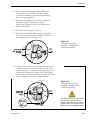
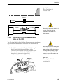
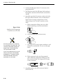
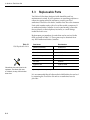
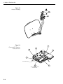
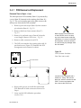
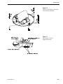
A Guide to TracVision SA
2.1.2 Kitpack
Table 2-1 lists the materials provided in the TracVision SA
kitpack.
Table 2-1
Kitpack Contents
Part
Qty.
Rocker Switch
1
12-0048
Switch Plate
1
19-0167
RF F-Connector
2
23-0170
Terminal Crimp (female)
5
23-0188-03
⁄4˝-20 x 5⁄8˝ hex screws
4
14-0250-0010
1
⁄4˝ flat washers
4
14-0251
Tie-wraps
5
22-0013
Flash kit cable and adapter
1
02-1029
1
2.2
The liquid-tight connectors on
TracVision SA may face either
forward or backward along the
centerline of the vehicle for more
convenient installation.
KVH Part No.
Choosing the Best Location
•
The ideal antenna site has a clear view of the
horizon/satellite all around.
•
Keep the antenna clear of any obstructions on the
roof (e.g., air conditioners).
•
Consider the location of the antenna relative to the
location of any equipment or necessary wiring
within the vehicle.
•
For best operation, mount the antenna on a
horizontal surface.
2.3
Mounting the Antenna Unit
1. Remove antenna unit from shipping container.
Always lift the antenna unit by the
gray baseplate, never by the
radome or any portion of the
antenna assembly!
2. Remove and save the 8 pan head screws and
sealing washers that hold radome to baseplate.
Carefully lift radome straight up until clear of
antenna assembly and set aside.
3. Position antenna unit in desired location on the
centerline of the vehicle with baseplate and
mounting plate arrows facing in the same
direction (either forward or backward). The proper
orientation is illustrated in Figure 2-1 on the
following page.
2-2